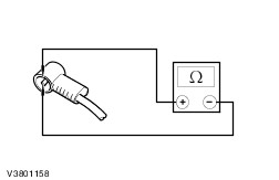
| Diagnosis and Testing Refer to Wiring Diagrams Section 415-01, for schematic and connector information. Inspection and Verification NOTE:If the code is entered incorrectly 3 times, the system will lock out. The component can only be unlocked by the manufacturer. - Verify the customer concern by operating the system.
- Visually inspect for obvious signs of mechanical or electrical damage.
Visual Inspection Chart | Mechanical | Electrical | - Audio unit damage
- Cassette player jammed, not loading
- Compact disc (CD) player jammed, not loading
- Antenna/alignment
| - Fuse(s)
- Circuit(s)
- Electrical connector(s)
- Audio unit
- Speakers
- Subwoofer amplifier
| - If an obvious cause for an observed or reported concern is found, correct the cause (if possible) before proceeding to the next step.
- If an obvious cause is not found, codes may be shown in the audio unit display. Check the audio unit display for the following Error Codes:
- for vehicles with 6006E or 9006 audio unit refer to the CD Error Codes - vehicles with Vehicles with 6006E or 9006 Audio Unit
- for vehicles with 6000 audio unit refer to the CD Error Codes - vehicles with 6000 Audio Unit
- for vehicles with CD changer refer to the CD Error Codes - vehicles with CD Changer
- If no error codes are displayed on the audio unit refer to the Self-Diagnostic Mode.
CD Error Codes Vehicles with 6006E or 9006 Audio Unit Error Codes | Error Code | Error Description | Error Rectification | | E1 | Communications Error | Install a new audio unit.
REFER to: Audio Unit (415-01 Audio Unit, Removal and Installation).
TEST the system for normal operation. | | E2 | Overtemp Error | The Audio unit is too hot, it will not work until it has cooled down. Check the heater duct(s) are not bleeding hot air on to the audio unit.
REFER to: Audio Unit (415-01 Audio Unit, Removal and Installation).
If the concern persists, INSTALL a new audio unit. TEST the system for normal operation. | | E3 | Mechanical Error | PRESS and HOLD the LOAD and EJECT buttons simutaneously. WAIT until the audio unit has checked through the CDs currently in the unit. TEST the system for normal operation. If the concern persists, DISCONNECT the audio unit power connector. WAIT 20 seconds and then CONNECT the audio unit power connector. WAIT until the audio unit has checked through the CDs currently in the unit. TEST the system for normal operation. If the error code is still displayed, INSTALL a new audio unit.
REFER to: Audio Unit (415-01 Audio Unit, Removal and Installation).
TEST the system for normal operation. | | E4 | Focus Error | CD is upside down or dirty. Clean the CD and try it again, if the error code is still displayed, INSERT a different CD. If the error code is still displayed. INSTALL a new audio unit.
REFER to: Audio Unit (415-01 Audio Unit, Removal and Installation).
TEST the system for normal operation. | | E5 | Overcurrent Error | Install a new audio unit.
REFER to: Audio Unit (415-01 Audio Unit, Removal and Installation).
TEST the system for normal operation. | CD Error Codes - vehicles with 6000 Audio Unit Error Codes | Error Code | Error Description | Error Rectification | | E11 | SPI Bus Failure | CHECK and REPAIR the wiring harness. If the wiring harness is OK, DISCONNECT the audio unit power connector, SWITCH the audio unit ON and OFF four times then CONNECT the audio unit power connector. TEST the system for normal operation. If the error code is still displayed, INSTALL a new audio unit.
REFER to: Audio Unit (415-01 Audio Unit, Removal and Installation).
TEST the system for normal operation. | | E12 | Communications Error | CHECK and REPAIR the wiring harness. If the wiring harness is OK, DISCONNECT the audio unit power connector, SWITCH the audio unit ON and OFF four times then CONNECT the audio unit power connector. TEST the system for normal operation. If the error code is still displayed, INSTALL a new audio unit.
REFER to: Audio Unit (415-01 Audio Unit, Removal and Installation).
TEST the system for normal operation. | | E14 | Overtemp Error | The Audio unit is too hot, unit will not work until it has cooled down. Check the heater duct(s) are not bleeding hot air on to the radio. If the concern persists, INSTALL a new audio unit.
REFER to: Audio Unit (415-01 Audio Unit, Removal and Installation).
TEST the system for normal operation. | | E15 | Mechanical Error | Install a new audio unit.
REFER to: Audio Unit (415-01 Audio Unit, Removal and Installation).
TEST the system for normal operation. | | E16 | CD Eject Failure | Install a new audio unit.
REFER to: Audio Unit (415-01 Audio Unit, Removal and Installation).
TEST the system for normal operation. | CD Error Codes - vehicles with CD Changer Error Codes | Error Code | Error Description | Error Rectification | | E2 | Communications Error | CHECK and REPAIR the CD changer harness. REFER to the Component Test in this section. If the CD changer harness is OK. INSTALL a new CD changer.
REFER to: Compact Disc (CD) Changer (415-01 Audio Unit, Removal and Installation).
TEST the system for normal operation. | | E3 | Focus Error | CD is upside down or dirty. Clean the CD and try it again, if the error code is still displayed, INSERT a different CD. If the error code is still displayed. INSTALL a new CD changer.
REFER to: Compact Disc (CD) Changer (415-01 Audio Unit, Removal and Installation).
TEST the system for normal operation. | | E4 | Overtemp Error | The CD changer is too hot, unit will not work until it has cooled down. Check the heater duct(s) are not bleeding hot air on to the CD changer. If the concern persists, INSTALL a new CD changer.
REFER to: Compact Disc (CD) Changer (415-01 Audio Unit, Removal and Installation).
TEST the system for normal operation. | | E5 | Mechanical Error | Install a new CD changer.
REFER to: Compact Disc (CD) Changer (415-01 Audio Unit, Removal and Installation).
TEST the system for normal operation. | Self-Diagnostic Mode - To enter the audio unit Self-Diagnostic Mode, switch the audio unit ON. Within four seconds depress the preset buttons 3 and 6 together.
- Release the preset buttons 3 and 6 and the audio unit will enter the Self-Diagnostic Mode.
- To navigate through the audio unit Self-Diagnostic Mode, depress the preset button 6.
- To exit the Self-Diagnostic Mode do not press any button on the audio unit for 10 seconds.
- If the Self-Diagnostic Mode cannot be accessed, use WDS to diagnose the audio unit.
Self-Diagnostic Mode | Test | Syntax Displayed | Circuit Tested | Description | | 1. FM waveband check. | FM frequency received. | Antenna signal. | Tests signal from the antenna cable. | | 2. Traffic Announcement. | TP | Traffic announcement volume level. | Allows adjustment of the volume. | | 3. Test speaker circuit left hand front speaker. | 4CH LF for four channel system 2CH LF for two channel system. | Left hand front speaker circuit. | Test speaker circuit. | | 4. Test speaker circuit right hand front speaker. | 4CH RF for four channel system 2CH RF for two channel system. | Right hand front speaker circuit. | Test speaker circuit. | | 5. Test speaker circuit left hand rear speaker. | 4CH LR for four channel system. | Left hand rear speaker circuit. | Test speaker circuit. | | 6. Test speaker circuit right hand rear speaker. | 4CH RR for four channel system. | Right hand rear speaker circuit. | Test speaker circuit. | | 7. Test communications with compact disc autochanger (if equipped). | CDDJ OK if communications are achieved and NO CDDJ if no communications are achieved. | Compact disc communications circuit. | Test compact disc circuit. | - If the concern remains after the Self-Diagnostic Mode, refer to the Symptom Chart.
Symptom Chart | Symptom | Possible Sources | Action | | The audio unit is inoperative or does not operate correctly | * Fuse(s). * Circuit. * Audio unit. | * | | The display is blank - radio and cassette player operate | * Audio unit. | * INSTALL a new audio unit.
REFER to: Audio Unit (415-01 Audio Unit, Removal and Installation).
| | Poor reception | * Antenna. * Antenna cable. * Audio unit. | * | | Distorted sound from one or more speakers (not all speakers) | * Speaker(s). * Circuit. * Audio unit. | * | | No sound from all of the speakers | * Speaker(s). * Circuit. * Audio unit. | * | | The CD player does not operate correctly | * Audio unit. | * INSTALL a new audio unit.
REFER to: Audio Unit (415-01 Audio Unit, Removal and Installation).
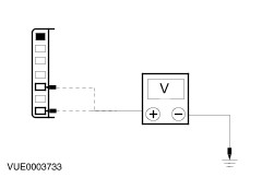
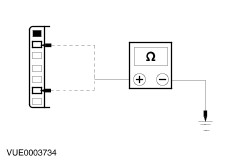
| | No sound from one or more of the speakers | * Circuit. * Audio unit. | * | | The CD changer is inoperative or does not operate correctly | * Fuse(s). * Circuit. * CD changer. | * | | The radio remote control is inoperative. | * Circuit. * Radio remote control. * Audio unit. | * | | The subwoofer is inoperative | * Subwoofer fuse. * Subwoofer. * Circuit. * Audio unit. | * | | Loud popping sound when cycling the ignition switch | * Circuit. * Subwoofer. | * | Pinpoint Tests NOTE:Use a digital multimeter for all electrical measurements. | PINPOINT TEST A : THE AUDIO UNIT IS INOPERATIVE - DOES NOT OPERATE CORRECTLY | | TEST CONDITIONS | DETAILS/RESULTS/ACTIONS | | A1: CHECK FOR VOLTAGE TO AUDIO UNIT | | | 1 Disconnect Audio Unit C443 or C446. | | | 2 Ignition switch in position I. | | | 3 Measure the voltage between the audio unit C443 or C446 pin 1, circuit 29-MD15 (OG/BK), harness side and ground; and between the audio unit C443 or C446 pin 3, circuit 75-MD15 (YE/GN), harness side and ground. | | | Are the voltages greater than 10 volts? Yes No REPAIR circuit 29-MD15 (OG/BK) or circuit 75-MD15 (YE/GN). TEST the system for normal operation. | | A2: CHECK THE AUDIO UNIT GROUND CIRCUITS FOR OPEN | | | 1 Ignition switch in position 0. | | | 2 Measure the resistance between the audio unit C443 or C446 pin 6, circuit 91-MD15 (BK/GN), harness side and ground; and between the audio unit C443 or C446 pin 2, circuit 91-MD34 (BK/YE), harness side and ground. | | | Are the resistances less than 1 ohm? Yes INSTALL a new audio unit.
REFER to: Audio Unit (415-01 Audio Unit, Removal and Installation).
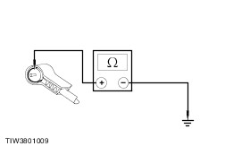
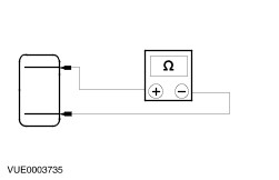
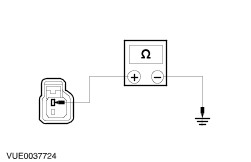
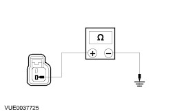
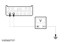
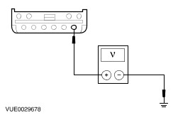
TEST the system for normal operation. No REPAIR circuit 91-MD15 (BK/GN) or 91-MD34 (BK/YE). TEST the system for normal operation. | | PINPOINT TEST B : POOR RECEPTION | | TEST CONDITIONS | DETAILS/RESULTS/ACTIONS | | B1: CHECK THE ANTENNA CABLE SHIELD | | | 1 Ignition switch in position 0. | | | 2 Ignition switch in position 0. | | | 3 Disconnect Antenna Cable. | | | 4 Disconnect the antenna cable from the audio unit. | | | 5 Measure the resistance between the antenna cable ground connector (shield), and ground. | | | Is the resistance less than 1 ohm? Yes No CLEAN and TIGHTEN the audio unit case ground and the antenna base connection to the body. If the concern persists, INSTALL a new antenna cable.
REFER to: Antenna Cable - LHD (415-02 Antenna, Removal and Installation) /
Antenna Cable - RHD (415-02 Antenna, Removal and Installation).
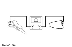
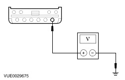
TEST the system for normal operation. | | B2: CHECK THE ANTENNA CENTER CONDUCTOR FOR OPEN | | | 1 Remove the antenna mast. | | | 2 Measure the resistance of the center conductor between the ends of the antenna cable. | | | Is the resistance less than 1 ohm? Yes No INSTALL a new antenna cable.
REFER to: Antenna Cable - LHD (415-02 Antenna, Removal and Installation) /
Antenna Cable - RHD (415-02 Antenna, Removal and Installation).
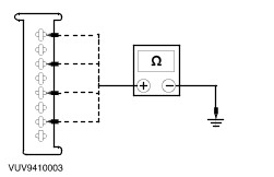
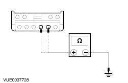
TEST the system for normal operation. | | B3: CHECK ANTENNA CABLE FOR SHORT | | | 1 Measure the resistance between the antenna center conductor and the antenna ground (shield). | | | Is the resistance greater than 10,000 ohms (open circuit)? Yes CLEAN and TIGHTEN the ground connections at the base of the antenna, audio unit case and battery negative cable to the body. If concern the persists, INSTALL a new audio unit.
REFER to: Audio Unit (415-01 Audio Unit, Removal and Installation).
TEST the system for normal operation. No INSTALL a new antenna cable.
REFER to: Antenna Cable - LHD (415-02 Antenna, Removal and Installation) /
Antenna Cable - RHD (415-02 Antenna, Removal and Installation).
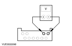
TEST the system for normal operation. | | PINPOINT TEST C : DISTORTED SOUND FROM ONE OR MORE SPEAKERS (NOT ALL SPEAKERS) | | TEST CONDITIONS | DETAILS/RESULTS/ACTIONS | | C1: CHECK THE SPEAKER RESISTANCE | | | 1 Disconnect Affected Speaker. | | | 2 Measure the resistance between the affected speaker pin 1 and pin 2, component side. | | | Is the resistance approximately 4.0 ohms? Yes No INSTALL a new speaker. TEST the system for normal operation. | | C2: CHECK SPEAKER INPUT FOR SHORT TO GROUND | | | 1 Disconnect Audio Unit C443. | | | 2 Measure the resistance between the affected speaker connector pin 1, harness side and ground. | | | Is the resistance greater than 10,000 ohms (open circuit)? Yes No REPAIR speaker input circuit. TEST the system for normal operation. | | C3: CHECK SPEAKER RETURN FOR SHORT TO GROUND | | | 1 Measure the resistance between the affected speaker connector pin 2, harness side and ground. | | | Is the resistance greater than 10,000 ohms (open circuit)? Yes INSTALL a new speaker. TEST the system for normal operation. If the concern persists, INSTALL a new audio unit.
REFER to: Audio Unit (415-01 Audio Unit, Removal and Installation).
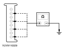
TEST the system for normal operation. No REPAIR speaker return circuit. TEST the system for normal operation. | | PINPOINT TEST D : NO SOUND FROM ALL OF THE SPEAKERS | | TEST CONDITIONS | DETAILS/RESULTS/ACTIONS | | D1: CHECK SPEAKER INPUT CIRCUIT FOR SHORT TO GROUND | | | 1 Ignition switch in position 0. | | | 2 Disconnect Audio Unit C442 or C450. | | | 3 Measure the resistance between the following audio unit connector pins and ground: - (Front left speaker) C442 or C450 pin 1, circuit 8-MD10 (WH/BK), harness side and ground.
- (Rear left speaker) C442 or C450 pin 3, circuit 8-MD11 (WH/GN), harness side and ground.
- (Front right speaker) C442 or C450 pin 5, circuit 8-MD17 (WH/RD), harness side and ground.
- (Rear right speaker) C442 or C450 pin 7, circuit 8-MD18 (WH), harness side and ground.
| | | Are the resistances greater than 10,000 ohms (open circuit)? Yes No REPAIR the circuit in question. TEST the system for normal operation. | | D2: CHECK SPEAKER RETURN CIRCUIT FOR SHORT TO GROUND | | | 1 Measure the resistance between the following audio unit connector pins and ground: - (Front left speaker) C442 or C450 pin 2, circuit 10-MD10 (GY/BK), harness side and ground.
- (Rear left speaker) C442 or C450 pin 4, circuit 10-MD11 (GY/WH), harness side and ground.
- (Front right speaker) C442 or C450 pin 6, circuit 10-MD17 (GY/RD), harness side and ground.
- (Rear right speaker) C442 or C450 pin 8, circuit 10-MD18 (GY), harness side and ground.
| | | Are the resistances greater than 10,000 ohms (open circuit)? Yes INSTALL a new audio unit.
REFER to: Audio Unit (415-01 Audio Unit, Removal and Installation).
TEST the system for normal operation. No REPAIR the circuit in question. TEST the system for normal operation. | | PINPOINT TEST E : NO SOUND FROM ONE OR MORE OF THE SPEAKERS | | TEST CONDITIONS | DETAILS/RESULTS/ACTIONS | | E1: CHECK THE SPEAKER RESISTANCE | | | 1 Disconnect Affected Speaker. | | | 2 Measure the resistance between the affected speaker pin 1 and pin 2, component side. | | | Is the resistance approximately 4.0 ohms? Yes No INSTALL a new speaker(s). TEST the system for normal operation. | | E2: CHECK SPEAKER CIRCUIT RESISTANCE - SPEAKER DISCONNECTED | | | 1 Disconnect Audio Unit C442 or C450. | | | 2 Measure the resistance between the audio unit C442 and the speaker connector pins for the inoperative speaker(s). - (Front left speaker) C442 or C450 pin 1, circuit 8-MD10 (WH/BK), harness side and C937 pin 2, circuit 8-MD28 (WH), harness side.
- (Front left speaker) C442 or C450 pin 2, circuit 10-MD10 (GY/BK), harness side and C937 pin 1, circuit 10-MD28 (GY), harness side.
- (Front right speaker) C442 or C450 pin 5, circuit 8-MD17 (WH/RD), harness side and C938 pin 2, circuit 8-MD28 (WH), harness side.
- (Front right speaker) C442 or C450 pin 6, circuit 10-MD17 (GY/RD), harness side and C938 pin 1, circuit 10-MD28 (BN), harness side.
- (Rear left speaker) C442 or C450 pin 3, circuit 8-MD11 (WH/GN), harness side and C939 pin 2, circuit 8-MD29 (WH/GN), harness side.
- (Rear left speaker) C442 or C450 pin 4, circuit 10-MD11 (GY/WH), harness side and C939 pin 1, circuit 10-MD11 (GY/WH), harness side.
- (Rear right speaker) C442 or C450 pin 7, circuit 8-MD18 (WH), harness side and C940 pin 2, circuit 8-MD29 (WH/GN), harness side.
- (Rear right speaker) C442 or C450 pin 8, circuit 10-MD18 (GY), harness side and C940 pin 1, circuit 10-MD29 (GY/WH), harness side.
| | | Is the resistance less than 1 ohm? Yes INSTALL a new speaker. TEST the system for normal operation. If concern persists, INSTALL a new audio unit.
REFER to: Audio Unit (415-01 Audio Unit, Removal and Installation).
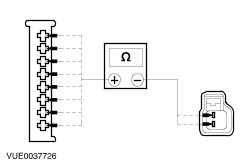
TEST the system for normal operation No REPAIR the circuit in question. TEST the system for normal operation. | | PINPOINT TEST F : THE CD CHANGER IS INOPERATIVE OR DOES NOT OPERATE CORRECTLY | | TEST CONDITIONS | DETAILS/RESULTS/ACTIONS | | F1: CHECK IN-LINE FUSE | | | 1 Check the 3 amp in-line fuse for the CD changer. | | | Is the 3 amp fuse OK? Yes No INSTALL a new fuse. TEST the system for normal operation. | | F2: TEST THE AUDIO UNIT TO CD CHANGER HARNESS | | | 1 Disconnect CD changer C465. | | | 2 Disconnect Radio Remote Control C437. | | | 3 Disconnect Audio unit C464. | | | 4 Carry out the CD changer harness component test. | | | Is the audio unit to CD changer harness OK? Yes No CHECK and REPAIR the CD changer harness. REFER to the Component Test in this section. If the CD changer harness is OK. INSTALL a new CD changer harness. TEST the system for normal operation. | | F3: CHECK FOR CORRECT OPERATION OF CD CHANGER | | | 1 Substitute a known good CD changer. | | | 2 Verify correct operation of the substitute CD changer. | | | Do all CD changer functions operate correctly? Yes INSTALL a new CD changer.
REFER to: Compact Disc (CD) Changer (415-01 Audio Unit, Removal and Installation).
TEST the system for normal operation. No REMOVE the substitute CD changer. INSTALL the original CD changer. INSTALL a new audio unit.
REFER to: Audio Unit (415-01 Audio Unit, Removal and Installation).
TEST the system for normal operation. | | PINPOINT TEST G : THE RADIO REMOTE CONTROL IS INOPERATIVE | | TEST CONDITIONS | DETAILS/RESULTS/ACTIONS | | G1: CHECK THE AUDIO UNIT OPERATES CORRECTLY WITHOUT USING THE REMOTE CONTROL | | | 1 Disconnect Radio Remote Control C437. | | | 2 Operate the audio unit with the remote control. | | | Does the audio unit operate correctly without using the remote control? Yes No INSTALL a new audio unit.
REFER to: Audio Unit (415-01 Audio Unit, Removal and Installation).
TEST the system for normal operation. | | G2: CHECK THE CIRCUIT 8-MD26 FOR OPEN | | | 1 Disconnect Audio Unit C447 or C445. | | | 2 Measure the resistance between the audio unit C447 or C445 pin 11, circuit 8-MD26 (WH/BK) harness side and the radio remote control C437 pin 1, circuit 8-MD26 (MH/BK) harness side. | | | Is the resistance less than 1 ohm? Yes No REPAIR circuit 8-MD26. TEST the system for normal operation. | | G3: CHECK CIRCUIT 9-MD26 FOR OPEN | | | 1 Measure the resistance between the audio unit C447 or C445 pin 12, circuit 9-MD26 (BN/YE) harness side and the radio remote control C437 pin 2, circuit 9-MD26 (BN/YE) harness side. | | | Is the resistance less than 1 ohm? Yes INSTALL a new radio remote control. TEST the system for normal operation. No REPAIR circuit 9-MD26 (BN/YE). TEST the system for normal operation. | | PINPOINT TEST H : THE SUBWOOFER AMPLIFIER IS INOPERATIVE | | TEST CONDITIONS | DETAILS/RESULTS/ACTIONS | | H1: CHECK THE SUBWOOFER AMPLIFIER FOR POWER | | | 1 Ignition switch in position 0. | | | 2 Disconnect Subwoofer Amplifier C990. | | | 3 Measure the voltages between the subwoofer amplifier C990 pin 5, circuit 30-MD19C (RD), harness side and ground; and between the subwoofer amplifier C990 pin 6, circuit 30-MD19D (RD), harness side and ground. | | | Are the voltages greater than 10 volts? Yes No REPAIR the circuit(s). TEST the system for normal operation. | | H2: CHECK THE SUBWOOFER AMPLIFIER FOR GROUND | | | 1 Measure the resistances between the subwoofer amplifier(s) C990 pin 2, circuit 31-MD19A (BK), harness side and ground; and between the subwoofer amplifier C990 pin 3, circuit 31-MD19B (BK), harness side and ground . | | | Are the resistances less than 1 ohm? Yes No REPAIR the circuit(s). TEST the system for normal operation. | | H3: CHECK CIRCUIT 8-MD19 (WH/RD) FOR VOLTAGE | | | 1 Measure the voltage between the subwoofer amplifier C990 pin 1, circuit 8-MD19 (WH/RD), harness side and ground. | | | Is voltage present? Yes REPAIR the circuit. TEST the system for normal operation. No | | H4: CHECK FOR AN AUDIO OUTPUT SIGNAL FROM THE AUDIO UNIT | | | 1 Switch the audio unit ON and select a known good radio station. | | | 2 Measure the voltage between the subwoofer amplifier C990 pin 7, circuit 1-MD23 (WH/BK), harness side and the subwoofer amplifier C990 pin 8, circuit 2-MD23 (GY/BK), harness side. | | | Is there a fluctuating AC voltage? Yes INSTALL a new subwoofer amplifier.
REFER to: Subwoofer Amplifier - 2.0L Duratec-ST (Zetec) (415-01 Audio Unit, Removal and Installation).
TEST the system for normal operation. No | | H5: CHECK AUDIO SIGNAL CIRCUITS FOR OPENS AND SHORTS TO GROUND | | | 1 Ignition switch in position 0. | | | 2 Measure the resistance between: - the subwoofer amplifier C990 pin 7, circuit 1-MD23 (WH/BK), harness side and the audio unit C447 pin 13, circuit 1-MD23 (WH/BK), harness side.
- the subwoofer amplifier C990 pin 8, circuit 2-MD23 (GY/BK), harness side and the audio unit C447 pin 14, circuit 2-MD23 (GY/BK), harness side.
- the subwoofer amplifier C990 pin 7, circuit 1-MD23 (WH/BK), harness side and ground; and pin 8, circuit 2-MD23 (GY/BK), harness side and ground.
| | | Is the resistance less than 1 ohm between the subwoofer amplifier and the audio unit and greater than 10,000 ohms (open circuit) between the subwoofer amplifier and ground? Yes INSTALL a new subwoofer amplifier.
REFER to: Subwoofer Amplifier - 2.0L Duratec-ST (Zetec) (415-01 Audio Unit, Removal and Installation).
TEST the system for normal operation. No REPAIR the circuit(s). TEST the system for normal operation. | | PINPOINT TEST I : LOUD POPPING SOUND WHEN CYCLING THE IGNITION SWITCH | | TEST CONDITIONS | DETAILS/RESULTS/ACTIONS | | I1: CHECK THE SUBWOOFER AMPLIFIER ENABLE LINE CIRCUIT 8-MD19 (WH/RD) FOR SHORT TO BATTERY POWER | | | 1 Ignition switch in position 0. | | | 2 Disconnect Subwoofer Amplifier C990. | | | 3 Measure the voltage between the subwoofer amplifier C990 pin 1, circuit 8-MD19 (WH/RD), harness side and ground. | | | Is the voltage greater than 10 volts? Yes REPAIR the circuit. TEST the system for normal operation. No INSTALL a new subwoofer amplifier.
REFER to: Subwoofer Amplifier - 2.0L Duratec-ST (Zetec) (415-01 Audio Unit, Removal and Installation).
TEST the system for normal operation. | Component Test CD Changer Harness -
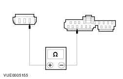
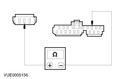
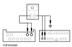
NOTE:Refer to Wiring Diagrams Section 415-01, for schematic and connector information. Using a digital multimeter, test the CD changer harness using the following table as a guide to meter lead placement as well as expected values. | CD Changer C465 | Audio Unit C464 | Expected Value | | Pin 1 | Pin 1 | Less than 1 ohm | | Pin 3 | Pin 3 | Less than 1 ohm | | Pin 5 | Pin 5 | Less than 1 ohm | | Pin 6 | Pin 6 | Less than 1 ohm | | Pin 7 | Pin 7 | Less than 1 ohm | | Pin 8 | Pin 8 | Less than 1 ohm | | Pin 9 | Pin 9 | Less than 1 ohm | | Pin 10 | Pin 10 | Less than 1 ohm | | Pin 11 | Pin 11 | Less than 1 ohm | | Pin 12 | Pin 12 | Less than 1 ohm | | CD Changer C465 | Negative Multimeter Lead | | | Pin 1 | Ground | Greater than 10,000 ohms (open circuit) | | Pin 3 | Ground | Greater than 10,000 ohms (open circuit) | | Pin 5 | Ground | Greater than 10,000 ohms (open circuit) | | Pin 6 | Ground | Greater than 10,000 ohms (open circuit) | | Pin 7 | Ground | Greater than 10,000 ohms (open circuit) | | Pin 8 | Ground | Greater than 10,000 ohms (open circuit) | | Pin 9 | Ground | Greater than 10,000 ohms (open circuit) | | Pin 10 | Ground | Greater than 10,000 ohms (open circuit) | | Pin 11 | Ground | Greater than 10,000 ohms (open circuit) | | Pin 12 | Ground | Greater than 10,000 ohms (open circuit) | - If routed here from a Pinpoint Test, return to the Pinpoint Test
|