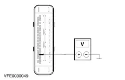
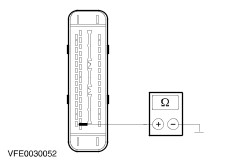
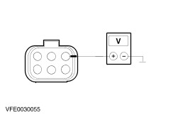
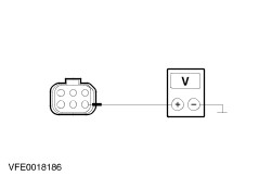
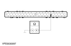
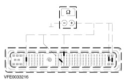
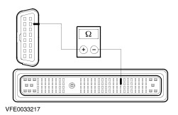
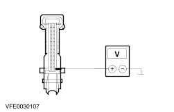
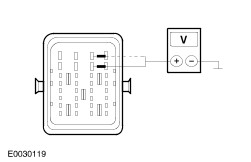
| Diagnosis and Testing Refer to Wiring Diagrams Section 418-00, for schematic and connector information. Special Tool(s) | | Digital multimeter 105-R0051 or equivalent | | | Terminal probe kit 29-011A | | | WDS (worldwide diagnostic system) 418-F224 | Inspection and Testing - Verify the customer concern.
- Visually inspect for obvious signs of mechanical or electrical damage.
Visual Inspection Chart | Electrical | - Fuse(s)
- Wiring harness
- Electrical connector(s)
| - If an obvious cause for an observed or reported concern is found, correct the cause (if possible) before proceeding to the next step.
- If the cause is not visually evident, verify the symptom and refer to the Symptom Chart.
Symptom Chart Symptom Chart | Symptom | Possible Sources | Action | | The air bag module does not respond to the diagnostic tool (K-Line ISO 9141) | * Fuse(s) * Circuit(s) * Air bag module | * | | The xenon control module/leveling sensor does not respond to the diagnostic tool (K-Line ISO 9141) | * Circuit(s) * Xenon control module/leveling sensor | * | | The electronic automatic temperature control (EATC) module does not respond to the diagnostic tool (K-Line ISO 9141, SCP Bus) | * Fuse(s) * Circuit(s) * Electronic automatic temperature control (EATC) module | * | | The ABS module or the electronic stability program (ESP) module does not respond to the diagnostic tool (K-Line ISO 9141, SCP Bus) | * Fuse(s) * Circuit(s) * ABS module or electronic stability program (ESP) module | * | | The booster heater does not respond to the diagnostic tool (K-Line ISO 9141) | * Fuse(s) * Circuit(s) * Booster heater | * | | The generic electronic module (GEM) does not respond to the diagnostic tool (K-Line ISO 9141) | * Fuse(s) * Circuit(s) * Ignition switch * Generic electronic module (GEM) | * | | The trip computer module does not respond to the diagnostic tool (K-Line ISO 9141) | * Fuse(s) * Circuit(s) * Trip computer module | * | | The powertrain control module (PCM) does not respond to the diagnostic tool (SCP Bus) | * Fuse(s) * Circuit(s) * Power-hold relay * Powertrain control module (PCM) | * | | The instrument cluster does not respond to the diagnostic tool (SCP Bus) | * Fuse(s) * Circuit(s) * Instrument cluster | * | | The auxiliary instrument cluster (only DURATEC-ST) does not respond to the diagnostic tool (SCP Bus) | * Fuse(s) * Circuit(s) * Auxiliary instrument cluster | * | | The powertrain control module (PCM) (only DURATEC-ST) does not respond to the diagnostic tool (CAN Bus) | * Fuse(s) * Circuit(s) * Powertrain control module (PCM) | * | | No module/network communication (SCP Bus) | * Circuit(s) * Powertrain control module (PCM) * Instrument cluster * Auxiliary instrument cluster * Electronic automatic temperature control (EATC) module * ABS module or electronic stability program (ESP) module | * | | No module/network communication (CAN Bus) (only Endura-DI and DuraTorq TDCi) | * Circuit(s) * Powertrain control module (PCM) * Injector driver module * Diesel pump unit | * | Pinpoint Tests | PINPOINT TEST A : THE AIR BAG MODULE DOES NOT RESPOND TO THE DIAGNOSTIC TOOL (K-LINE ISO 9141) | | TEST CONDITIONS | DETAILS/RESULTS/ACTIONS | | A1: CHECK FUSE F60 | | | 1 Ignition switch in position 0. | | | 2 CHECK fuse F60 (CJB). | | | Is the fuse OK? Yes No INSTALL a new fuse F60 (7.5 A). If the fuse blows again, LOCATE and REPAIR the short circuit by using the wiring diagrams. TEST the system for normal operation. | | A2: CHECK THE VOLTAGE AT FUSE F60 | | | 1 Connect fuse F60 (CJB). | | | 2 Ignition switch in position II. | | | 3 Measure the voltage between fuse F60 (7.5 A) and ground. | | | Is battery voltage indicated? Yes No REPAIR the power supply of fuse F60 by using the wiring diagrams. If necessary INSTALL a new CJB. TEST the system for normal operation. | | A3: CHECK THE SYSTEM BY USING THE WDS | | | 1 Ignition switch in position 0. | | | 2 Connect the diagnostic tool. | | | 3 Check the system by using the WDS. | | | Are any error-codes (DTC's) indicated? Yes WORK through the DTC's, according to the WDS instruction. CLEAR the error memory and TEST the system for normal operation. No | | A4: CHECK THE VOLTAGE AT THE AIR BAG MODULE | WARNING:To minimize the possibility of premature deployment, wait at least one minute after disconnecting the battery ground cable(s) before disconnecting any supplemental restraint system electrical connectors. Failure to follow this instruction may result in personal injury. | WARNING:To minimize the possibility of premature deployment, do not use radio key code savers when working on the supplemental restraint system. Failure to follow this instruction may result in personal injury. | | | 1 Ignition switch in position 0. | | | 2 Disconnect battery ground cable. | | | 3 Disconnect connector C424 of air bag module. | | | 4 Connect battery ground cable. | | | 5 Ignition switch in position II. | | | 6 Measure the voltage between air bag module, connector C424, pin 8, circuit 15-JA10 (GN/OG), harness side and ground. | | | Is battery voltage indicated? Yes No LOCATE and REPAIR the open in circuit 15-JA10 (GN/OG) between fuse F60 and air bag module, by using the wiring diagrams. If necessary INSTALL a new CJB. TEST the system for normal operation. | | A5: CHECK THE GROUND CONNECTION OF THE AIR BAG MODULE | | | 1 Ignition switch in position 0. | | | 2 Measure the resistance between air bag module, connector C424, pin 9, circuit 91-JA10 (BK/RD), harness side and ground. | | | Is the resistance less than 2 ohms? Yes No LOCATE and REPAIR the open in circuit 91-JA10 (BK/RD) between air bag module and ground G41, by using the wiring diagrams. TEST the system for normal operation. | | A6: CHECK THE CIRCUIT BETWEEN AIR BAG MODULE AND DATA LINK CONNECTOR (DLC) FOR OPEN | | | 1 Measure the resistance between air bag module, connector C424, pin 7, circuit 8-EE7 (WH/RD), harness side and DLC, connector C200, pin 7, circuit 8-EE10 (WH/BK). | | | Is the resistance less than 2 ohms? Yes CHECK the air bag module, if necessary INSTALL a new one. TEST the system for normal operation. No LOCATE and REPAIR the open in circuit 8-EE7 (WH/BK) between air bag module and splice S10 (DLC), by using the wiring diagrams. TEST the system for normal operation. | | PINPOINT TEST B : THE XENON CONTROL MODULE/LEVELING SENSOR DOES NOT RESPOND TO THE DIAGNOSTIC TOOL (K-LINE ISO 9141) | | TEST CONDITIONS | DETAILS/RESULTS/ACTIONS | | B1: CHECK THE SYSTEM BY USING THE WDS | | | 1 Ignition switch in position 0. | | | 2 Connect the diagnostic tool. | | | 3 Check the system by using the WDS. | | | Are any error-codes (DTC's) indicated? Yes WORK through the DTC's, according to the WDS instruction. CLEAR the error memory and TEST the system for normal operation. No No response to the diagnostic tool at the data link connector (DLC) and at the xenon headlamps diagnostic connector: GO to B3. No response to the diagnostic tool at the xenon headlamps diagnostic connector only: GO to B2. | | B2: CHECK THE CIRCUIT BETWEEN XENON HEADLAMPS DIAGNOSTIC CONNECTOR AND DLC FOR OPEN | | | 1 Ignition switch in position 0. | | | 2 Measure the resistance between xenon headlamps diagnostic connector C199, pin 1, circuit 8-EE19A (WH/BK) and DLC, connector C200, pin 7, circuit 8-EE10 (WH/BK). | | | Is the resistance less than 2 ohms? Yes LOCATE and REPAIR the open in circuit 91-EE19 (BK/RD) between xenon headlamps diagnostic connector and splice S118 (ground G1), by using the wiring diagrams. TEST the system for normal operation. No LOCATE and REPAIR the open in circuit 8-EE19A (WH/BK) between xenon headlamps diagnostic connector and splice S140 (DLC), by using the wiring diagrams. TEST the system for normal operation. | | B3: CHECK THE VOLTAGE AT THE XENON CONTROL MODULE/LEVELING SENSOR | | | 1 Ignition switch in position 0. | | | 2 Disconnect connector C838 of xenon control module/leveling sensor. | | | 3 Ignition switch in position II. | | | 4 Measure the voltage between xenon control module/leveling sensor, connector C838, pin 2, circuit 15-XL28C (GN/OG), harness side and ground. | | | Is battery voltage indicated? Yes No LOCATE and REPAIR the open in circuit 15-XL28C (GN/OG) between splice S114 (fuse F53) and xenon control module/leveling sensor, by using the wiring diagrams. TEST the system for normal operation. | | B4: CHECK THE GROUND CONNECTION OF THE XENON CONTROL MODULE/LEVELING SENSOR | | | 1 Ignition switch in position 0. | | | 2 Measure the resistance between xenon control module/leveling sensor, connector C838, pin 1, circuit 91-XL31 (BK/BU), harness side and ground. | | | Is the resistance less than 2 ohms? Yes No LOCATE and REPAIR the open in circuit 91-XL31 (BK/BU) between xenon control module/leveling sensor and splice S118 (ground G1), by using the wiring diagrams. TEST the system for normal operation. | | B5: CHECK THE CIRCUIT BETWEEN XENON CONTROL MODULE/LEVELING SENSOR AND DLC FOR OPEN | | | 1 Measure the resistance between xenon control module/leveling sensor, connector C838, pin 5, circuit 8-EE19 (WH/BK), harness side and DLC, connector C200, pin 7, circuit 8-EE10 (WH/BK). | | | Is the resistance less than 2 ohms? Yes CHECK the xenon control module/leveling sensor, if necessary INSTALL a new one. TEST the system for normal operation. No LOCATE and REPAIR the open in circuit 8-EE19 (WH/BK) between xenon control module/leveling sensor and splice S140 (DLC), by using the wiring diagrams. TEST the system for normal operation. | | PINPOINT TEST C : THE ELECTRONIC AUTOMATIC TEMPERATURE CONTROL (EATC) MODULE DOES NOT RESPOND TO THE DIAGNOSTIC TOOL (K-LINE ISO 9141, SCP BUS) | | TEST CONDITIONS | DETAILS/RESULTS/ACTIONS | | C1: CHECK FUSE F45 | | | 1 Ignition switch in position 0. | | | 2 CHECK fuse F45 (CJB). | | | Is the fuse OK? Yes No INSTALL a new fuse F45 (7.5 A). If the fuse blows again, LOCATE and REPAIR the short circuit by using the wiring diagrams. TEST the system for normal operation. | | C2: CHECK THE VOLTAGE AT FUSE F45 | | | 1 Connect fuse F45 (CJB). | | | 2 Ignition switch in position II. | | | 3 Measure the voltage between fuse F45 (7.5 A) and ground. | | | Is battery voltage indicated? Yes No REPAIR the power supply of fuse F45 by using the wiring diagrams. If necessary INSTALL a new CJB. TEST the system for normal operation. | | C3: CHECK THE SYSTEM BY USING THE WDS | | | 1 Ignition switch in position 0. | | | 2 Connect the diagnostic tool. | | | 3 Check the system by using the WDS. | | | Are any error-codes (DTC's) indicated? Yes WORK through the DTC's, according to the WDS instruction. CLEAR the error memory and TEST the system for normal operation. No No response to the diagnostic tool (K-Line ISO 9141): GO to C4. No module/network communication (SCP Bus): GO to C9. | | C4: CHECK THE VOLTAGE AT THE ELECTRONIC AUTOMATIC TEMPERATURE CONTROL (EATC) MODULE (WITH IGNITION OFF) | | | 1 Ignition switch in position 0. | | | 2 Disconnect connector C380 of EATC module. | | | 3 Measure the voltage between EATC module, connector C380, pin 8, circuit 29-FA13 (OG), harness side and ground. | | | Is battery voltage indicated? Yes No LOCATE and REPAIR the open in circuit 29-FA13 (OG) between splice S49 (fuse F36) and EATC module, by using the wiring diagrams. TEST the system for normal operation. | | C5: CHECK THE VOLTAGE AT THE EATC MODULE (WITH IGNITION ON) | | | 1 Ignition switch in position II. | | | 2 Measure the voltage between EATC module, connector C380, pin 10, circuit 15-FA13 (GN/RD), harness side and ground. | | | Is battery voltage indicated? Yes No LOCATE and REPAIR the open in circuit between fuse F45 (CJB) and EATC module, by using the wiring diagrams. If necessary INSTALL a new CJB. TEST the system for normal operation. | | C6: CHECK THE GROUND CONNECTION OF THE EATC MODULE | | | 1 Ignition switch in position 0. | | | 2 Measure the resistance between EATC module, connector C380, pin 12, circuit 91-FA13 (BK/OG), harness side and ground. | | | Is the resistance less than 2 ohms? Yes No LOCATE and REPAIR the open in circuit 91-FA13 (BK/OG) between EATC module and splice S12 (ground G41), by using the wiring diagrams. TEST the system for normal operation. | | C7: CHECK THE VOLTAGE AT THE EATC MODULE (WITH ENGINE IS RUNNING) | | | 1 Ignition switch in position III. | | | 2 Measure the voltage between EATC module, connector C380, pin 11, circuit 64-HB6(A) (BU), harness side and ground. | | | Is battery voltage indicated? Yes No LOCATE and REPAIR the open in circuit 64-HB6(A) between engine run relay (BJB) and EATC module, by using the wiring diagrams. TEST the system for normal operation. | | C8: CHECK CIRCUIT 8-EE3 (WH/RD) (K-LINE ISO 9141 BUS) BETWEEN EATC MODULE AND DATA LINK CONNECTOR (DLC) FOR OPEN | | | 1 Ignition switch in position 0. | | | 2 Disconnect connector C539 of EATC module. | | | 3 Measure the resistance between EATC module, connector C539, pin 23, circuit 8-EE3 (WH/RD), harness side and DLC, connector C200, pin 7, circuit 8-EE10 (WH/BK). | | | Is the resistance less than 2 ohms? Yes CHECK the EATC module, if necessary INSTALL a new one. TEST the system for normal operation. No LOCATE and REPAIR the open in circuit 8-EE3 (WH/RD) between EATC module and splice S10 (DLC), by using the wiring diagrams. TEST the system for normal operation. | | C9: CHECK CIRCUIT 4-EG1 (GY/RD) (SCP BUS) BETWEEN ELECTRONIC AUTOMATIC TEMPERATURE CONTROL (EATC) MODULE AND DATA LINK CONNECTOR (DLC) FOR OPEN | | | 1 Ignition switch in position 0. | | | 2 Disconnect connector C539 of EATC module. | | | 3 Measure the resistance between EATC module, connector C539, pin 22, circuit 4-EG1 (GY/RD), harness side and DLC, connector C200, pin 2, circuit 4-EG7 (GY/RD). | | | Is the resistance less than 2 ohms? Yes No LOCATE and REPAIR the open in circuit 4-EG1 (GY/RD) between EATC module and splice S16 (DLC), by using the wiring diagrams. TEST the system for normal operation. | | C10: CHECK CIRCUIT 5-EG1 (BU/RD) (SCP BUS) BETWEEN EATC MODULE AND DLC FOR OPEN | | | 1 Measure the resistance between EATC module, connector C539, pin 6, circuit 5-EG1 (BU/RD), harness side and DLC, connector C200, pin 10, circuit 5-EG7 (BU/RD). | | | Is the resistance less than 2 ohms? Yes CHECK the EATC module, if necessary INSTALL a new one. TEST the system for normal operation. No LOCATE and REPAIR the open in circuit 5-EG1 (BU/RD) between EATC module and splice S17 (DLC), by using the wiring diagrams. TEST the system for normal operation. | | PINPOINT TEST D : THE ABS MODULE OR THE ELECTRONIC STABILITY PROGRAM (ESP) MODULE DOES NOT RESPOND TO THE DIAGNOSTIC TOOL (K-LINE ISO 9141, SCP BUS) | | TEST CONDITIONS | DETAILS/RESULTS/ACTIONS | | D1: CHECK FUSE F21 | | | 1 Ignition switch in position 0. | | | 2 CHECK fuse F21 (BJB). | | | Is the fuse OK? Yes No INSTALL a new fuse F21 (20 A). If the fuse blows again, LOCATE and REPAIR the short circuit by using the wiring diagrams. TEST the system for normal operation. | | D2: CHECK THE VOLTAGE AT FUSE F21 | | | 1 Connect fuse F21 (BJB). | | | 2 Ignition switch in position II. | | | 3 Measure the voltage between fuse F21 (20 A) and ground. | | | Is battery voltage indicated? Yes No REPAIR the power supply of fuse F21 by using the wiring diagrams. If necessary INSTALL a new BJB. TEST the system for normal operation. | | D3: CHECK FUSE F11 | | | 1 Ignition switch in position 0. | | | 2 CHECK fuse F11 (BJB). | | | Is the fuse OK? Yes No INSTALL a new fuse F11 (30 A). If the fuse blows again, LOCATE and REPAIR the short circuit by using the wiring diagrams. TEST the system for normal operation. | | D4: CHECK THE VOLTAGE AT FUSE F11 | | | 1 Connect fuse F11 (BJB). | | | 2 Ignition switch in position II. | | | 3 Measure the voltage between fuse F11 (30 A) and ground. | | | Is battery voltage indicated? Yes No REPAIR the power supply of fuse F11 by using the wiring diagrams. If necessary INSTALL a new BJB. TEST the system for normal operation. | | D5: CHECK FUSE F46 | | | 1 Ignition switch in position 0. | | | 2 CHECK fuse F46 (CJB). | | | Is the fuse OK? Yes No INSTALL a new fuse F46 (7.5 A). If the fuse blows again, LOCATE and REPAIR the short circuit by using the wiring diagrams. TEST the system for normal operation. | | D6: CHECK THE VOLTAGE AT FUSE F46 | | | 1 Connect fuse F46 (CJB). | | | 2 Ignition switch in position II. | | | 3 Measure the voltage between fuse F46 (7.5 A) and ground. | | | Is battery voltage indicated? Yes No REPAIR the power supply of fuse F46, by using the wiring diagrams. If necessary INSTALL a new CJB. TEST the system for normal operation. | | D7: CHECK THE SYSTEM BY USING THE WDS | | | 1 Ignition switch in position 0. | | | 2 Connect the diagnostic tool. | | | 3 Check the system by using the WDS. | | | Are any error-codes (DTC's) indicated? Yes WORK through the DTC's, according to the WDS instruction. CLEAR the error memory and TEST the system for normal operation. No No response to the diagnostic tool (K-Line ISO 9141): GO to D8. No module/network communication (SCP Bus): GO to D14. | | D8: CHECK THE VOLTAGE AT THE ABS MODULE OR ELECTRONIC STABILITY PROGRAM (ESP) MODULE | | | 1 Ignition switch in position 0. | | | 2 Disconnect connector C840 of ABS module or ESP module. | | | 3 Measure the voltage between ABS module or ESP module, connector C840, pin 32, circuit 30-CF6A (RD), harness side and ground. | | | Is battery voltage indicated? Yes No LOCATE and REPAIR the open in circuit 30-CF6A (RD) between fuse F21 (BJB) and ABS module or ESP module, by using the wiring diagrams. TEST the system for normal operation. | | D9: CHECK THE VOLTAGE AT THE ABS MODULE OR ESP MODULE | | | 1 Measure the voltage between ABS module or ESP module, connector C840, pin 1, circuit 30-CF13A (RD), harness side and ground. | | | Is battery voltage indicated? Yes No LOCATE and REPAIR the open in circuit 30-CF13A (RD) between fuse F11 (BJB) and ABS module or ESP module, by using the wiring diagrams. TEST the system for normal operation. | | D10: CHECK THE VOLTAGE AT THE ABS MODULE OR ESP MODULE | | | 1 Ignition switch in position II. | | | 2 Measure the voltage between ABS module or ESP module, connector C840, pin 4, circuit 15-CF6A (GN/YE), harness side and ground. | | | Is battery voltage indicated? Yes No LOCATE and REPAIR the open in circuit between fuse F46 (CJB) and ABS module or ESP module, by using the wiring diagrams. If necessary INSTALL a new CJB. TEST the system for normal operation. | | D11: CHECK THE GROUND CONNECTION OF THE ABS MODULE OR ESP MODULE | | | 1 Ignition switch in position 0. | | | 2 Measure the resistance between ABS module or ESP module, connector C840, pin 16, circuit 91-CF6 (BK/YE), harness side and ground. | | | Is the resistance less than 2 ohms? Yes No LOCATE and REPAIR the open in circuit 91-CF6 (BK/YE) between ABS module or ESP module and splice S141 (ground G55), by using the wiring diagrams. TEST the system for normal operation. | | D12: CHECK THE GROUND CONNECTION OF THE ABS MODULE OR ESP MODULE | | | 1 Measure the resistance between ABS module or ESP module, connector C840, pin 47, circuit 91-CF13 (BK/BU), harness side and ground. | | | Is the resistance less than 2 ohms? Yes No LOCATE and REPAIR the open in circuit 91-CF13 (BK/BU) between ABS module or ESP module and splice S141 (ground G55), by using the wiring diagrams. TEST the system for normal operation. | | D13: CHECK THE CIRCUIT 8-EE6(A) (WH) (K-LINE ISO 9141) BETWEEN ABS MODULE OR ESP MODULE AND DATA LINK CONNECTOR (DLC) FOR OPEN | | | 1 Measure the resistance between ABS module or ESP module, connector C840, pin 2, circuit 8-EE6(A) (WH), harness side and DLC, connector C200, pin 7, circuit 8-EE10 (WH/BK). | | | Is the resistance less than 2 ohms? Yes CHECK the ABS module or ESP module, if necessary INSTALL a new one. TEST the system for normal operation. No LOCATE and REPAIR the open in circuit 8-EE6(A) (WH) between ABS module or ESP module and splice S140 (DLC), by using the wiring diagrams. TEST the system for normal operation. | | D14: CHECK CIRCUIT 4-EG6 (GY) (SCP BUS) BETWEEN ABS MODULE OR ELECTRONIC STABILITY PROGRAM (ESP) MODULE AND DATA LINK CONNECTOR (DLC) FOR OPEN | | | 1 Ignition switch in position 0. | | | 2 Disconnect connector C840 of ABS module or ESP module. | | | 3 Measure the resistance between ABS module or ESP module, connector C840, pin 12, circuit 4-EG6 (GY), harness side and DLC, connector C200, pin 2, circuit 4-EG7 (GY/RD). | | | Is the resistance less than 2 ohms? Yes No LOCATE and REPAIR the open in circuit 4-EG6 (GY) between ABS module or ESP module and splice S16 (DLC) by using the wiring diagrams. TEST the system for normal operation. | | D15: CHECK CIRCUIT 5-EG7 (BU) (SCP BUS) BETWEEN ABS MODULE OR ESP MODULE AND DLC FOR OPEN | | | 1 Measure the resistance between ABS module or ESP module, connector C840, pin 14, circuit 5-EG6 (BU), harness side and DLC, connector C200, pin 10, circuit 5-EG7 (BU/RD). | | | Is the resistance less than 2 ohms? Yes CHECK the ABS module or ESP module, if necessary INSTALL a new one. TEST the system for normal operation. No LOCATE and REPAIR the open in circuit 5-EG6 (BU) between ABS module or ESP module and splice S17 (DLC), by using the wiring diagrams. TEST the system for normal operation. | | PINPOINT TEST E : THE BOOSTER HEATER DOES NOT RESPOND TO THE DIAGNOSTIC TOOL (K-LINE ISO 9141) | | TEST CONDITIONS | DETAILS/RESULTS/ACTIONS | | E1: CHECK FUSE F23 | | | 1 Ignition switch in position 0. | | | 2 CHECK fuse F23 (BJB). | | | Is the fuse OK? Yes No INSTALL a new fuse F23 (20 A). If the fuse blows again, LOCATE and REPAIR the short circuit by using the wiring diagrams. TEST the system for normal operation. | | E2: CHECK THE VOLTAGE AT FUSE F23 | | | 1 Connect fuse F23 (BJB). | | | 2 Measure the voltage between fuse F23 (20 A) and ground. | | | Is battery voltage indicated? Yes No REPAIR the power supply of fuse F23 by using the wiring diagrams. If necessary INSTALL a new BJB. TEST the system for normal operation. | | E3: CHECK THE SYSTEM BY USING THE WDS | | | 1 Ignition switch in position 0. | | | 2 Connect the diagnostic tool. | | | 3 Check the system by using the WDS. | | | Are any error-codes (DTC's) indicated? Yes WORK through the DTC's, according to the WDS instruction. CLEAR the error memory and TEST the system for normal operation. No | | E4: CHECK THE VOLTAGE AT THE BOOSTER HEATER (IGNITION OFF) | | | 1 Ignition switch in position 0. | | | 2 Disconnect connector C878 of booster heater. | | | 3 Measure the voltage between booster heater, connector C878, pin 1, circuit 30-RD18 (RD), harness side and ground. | | | Is battery voltage indicated? Yes No LOCATE and REPAIR the open in circuit 30-RD18 (RD) between fuse F23 (BJB) and booster heater, by using the wiring diagrams. TEST the system for normal operation. | | E5: CHECK THE VOLTAGE AT THE BOOSTER HEATER (IGNITION ON) | | | 1 Ignition switch in position II. | | | 2 Measure the voltage between booster heater, connector C878, pin 4, circuit 15-RD18 (GN/RD), harness side and ground. | | | Is battery voltage indicated? Yes No LOCATE and REPAIR the open in circuit 15-RD18 (GN/RD) between splice S117 (Power-hold relay) and booster heater, by using the wiring diagrams. TEST the system for normal operation. | | E6: CHECK THE GROUND CONNECTION OF THE BOOSTER HEATER | | | 1 Ignition switch in position 0. | | | 2 Measure the resistance between booster heater, connector C878, pin 2, circuit 31-RD18 (BK), harness side and ground. | | | Is the resistance less than 2 ohms? Yes No LOCATE and REPAIR the open in circuit 31-RD18 (BK) between booster heater and splice S121 (ground G37), by using the wiring diagrams. TEST the system for normal operation. | | E7: CHECK THE CIRCUIT BETWEEN BOOSTER HEATER AND DATA LINK CONNECTOR (DLC) FOR OPEN | | | 1 Measure the resistance between booster heater, connector C878, pin 3, circuit 8-EE11 (WH/VT), harness side and DLC, connector C200, pin 7, circuit 8-EE10 (WH/BK), harness side. | | | Is the resistance less than 2 ohms? Yes CHECK the booster heater, if necessary INSTALL a new one. TEST the system for normal operation. No LOCATE and REPAIR the open in circuit 8-EE11 (WH/VT) between booster heater and splice S140 (DLC), by using the wiring diagrams. TEST the system for normal operation. | | PINPOINT TEST F : THE GENERIC ELECTRONIC MODULE (GEM) DOES NOT RESPOND TO THE DIAGNOSTIC TOOL (K-LINE ISO 9141) | | TEST CONDITIONS | DETAILS/RESULTS/ACTIONS | | F1: CHECK FUSE F63 | | | 1 Ignition switch in position 0. | | | 2 CHECK fuse F63 (CJB). | | | Is the fuse OK? Yes No INSTALL a new fuse F63 (20 A). If the fuse blows again, LOCATE and REPAIR the short circuit by using the wiring diagrams. TEST the system for normal operation. | | F2: CHECK THE VOLTAGE AT FUSE F63 | | | 1 Connect fuse F63 (CJB). | | | 2 Measure the voltage between fuse F63 (20 A) and ground. | | | Is battery voltage indicated? Yes No REPAIR the power supply of fuse F63 by using the wiring diagrams. If necessary INSTALL a new CJB. TEST the system for normal operation. | | F3: CHECK FUSE F32 | | | 1 Ignition switch in position 0. | | | 2 CHECK fuse F32 (CJB). | | | Is the fuse OK? Yes No INSTALL a new fuse F32 (15 A). If the fuse blows again, LOCATE and REPAIR the short circuit by using the wiring diagrams. TEST the system for normal operation. | | F4: CHECK THE VOLTAGE AT FUSE F32 | | | 1 Connect fuse F32 (CJB). | | | 2 Measure the voltage between fuse F32 (15 A) and ground. | | | Is battery voltage indicated? Yes No REPAIR the power supply of fuse F32 by using the wiring diagrams. If necessary INSTALL a new CJB. TEST the system for normal operation. | | F5: CHECK THE SYSTEM BY USING THE WDS | | | 1 Ignition switch in position 0. | | | 2 Connect the diagnostic tool. | | | 3 Check the system by using the WDS. | | | Are any error-codes (DTC's) indicated? Yes WORK through the DTC's, according to the WDS instruction. CLEAR the error memory and TEST the system for normal operation. No | | F6: CHECK THE VOLTAGE AT THE GENERIC ELECTRONIC MODULE (GEM) | | | 1 Ignition switch in position 0. | | | 2 Disconnect connector C103 of GEM. | | | 3 Measure the voltage between GEM, connector C103, pin 1, circuit 29-AA17 (OG/WH), harness side and ground. | | | Is battery voltage indicated? Yes No LOCATE and REPAIR the open in circuit between fuse F63 (CJB) and GEM, by using the wiring diagrams. If necessary INSTALL a new CJB. TEST the system for normal operation. | | F7: CHECK THE VOLTAGE AT THE GEM | | | 1 Measure the voltage between GEM, connector C103, pin 5, circuit 29-DK20 (OG/GN), harness side and ground. | | | Is battery voltage indicated? Yes No LOCATE and REPAIR the open in circuit between fuse F32 (CJB) and GEM, by using the wiring diagrams. If necessary INSTALL a new CJB. TEST the system for normal operation. | | F8: CHECK THE GROUND CONNECTION OF THE GEM | | | 1 Disconnect connector C104 of GEM. | | | 2 Measure the resistance between GEM, connector C104, pin 1, circuit 91-DK20 (BK/RD), harness side and ground. | | | Is the resistance less than 2 ohms? Yes No LOCATE and REPAIR the open in circuit 91-DK20 (BK/RD) between GEM and splice S12 (ground G41), by using the wiring diagrams. TEST the system for normal operation. | | F9: CHECK THE GROUND CONNECTION OF THE GEM | | | 1 Disconnect connector C101 of GEM. | | | 2 Measure the resistance between GEM, connector C101, pin 5, circuit 31-DK20 (BK), harness side and ground. | | | Is the resistance less than 2 ohms? Yes No LOCATE and REPAIR the open in circuit 31-DK20 (BK) between GEM and ground G53, by using the wiring diagrams. TEST the system for normal operation. | | F10: CHECK THE CIRCUIT 8-EE9 (WH/GN) BETWEEN GEM AND DATA LINK CONNECTOR (DLC) FOR OPEN | | | 1 Measure the resistance between GEM, connector C104, pin 16, circuit 8-EE9 (WH/GN), harness side and DLC, connector C200, pin 7, circuit 8-EE10 (WH/BK). | | | Is the resistance less than 2 ohms? Yes CHECK the GEM, if necessary INSTALL a new one. TEST the system for normal operation. No LOCATE and REPAIR the open in circuit 8-EE9 (WH/GN) between GEM and splice S10 (DLC), by using the wiring diagrams. TEST the system for normal operation. | | PINPOINT TEST G : THE TRIP COMPUTER MODULE DOES NOT RESPOND TO THE DIAGNOSTIC TOOL (K-LINE ISO 9141) | | TEST CONDITIONS | DETAILS/RESULTS/ACTIONS | | G1: CHECK FUSE F61 | | | 1 Ignition switch in position 0. | | | 2 CHECK fuse F61 (CJB). | | | Is the fuse OK? Yes No INSTALL a new fuse F61 (7.5 A). If the fuse blows again, LOCATE and REPAIR the short circuit by using the wiring diagrams. TEST the system for normal operation. | | G2: CHECK THE VOLTAGE AT FUSE F61 | | | 1 Connect fuse F61 (CJB). | | | 2 Ignition switch in position II. | | | 3 Measure the voltage between fuse F61 (7.5 A) and ground. | | | Is battery voltage indicated? Yes No REPAIR the power supply of fuse F61 by using the wiring diagrams. If necessary INSTALL a new CJB. TEST the system for normal operation. | | G3: CHECK FUSE F36 | | | 1 Ignition switch in position 0. | | | 2 CHECK fuse F36 (CJB). | | | Is the fuse OK? Yes No INSTALL a new fuse F36 (7.5 A). If the fuse blows again, LOCATE and REPAIR the short circuit by using the wiring diagrams. TEST the system for normal operation. | | G4: CHECK THE VOLTAGE AT FUSE F36 | | | 1 Connect fuse F36 (CJB). | | | 2 Measure the voltage between fuse F36 (7.5 A) and ground. | | | Is battery voltage indicated? Yes No REPAIR the power supply of fuse F36 by using the wiring diagrams. If necessary INSTALL a new CJB. TEST the system for normal operation. | | G5: CHECK THE SYSTEM BY USING THE WDS | | | 1 Ignition switch in position 0. | | | 2 Connect the diagnostic tool. | | | 3 Check the system by using the WDS. | | | Are any error-codes (DTC's) indicated? Yes WORK through the DTC's, according to the WDS instruction. CLEAR the error memory and TEST the system for normal operation. No | | G6: CHECK THE VOLTAGE AT THE TRIP COMPUTER MODULE (IGNITION ON) | | | 1 Ignition switch in position 0. | | | 2 Disconnect connector C467 of trip computer module. | | | 3 Ignition switch in position II. | | | 4 Measure the voltage between trip computer module, connector C467, pin 18, circuit 15-GE6 (GN/YE), harness side and ground. | | | Is battery voltage indicated? Yes No LOCATE and REPAIR the open in circuit between fuse F61 (CJB) and trip computer module, by using the wiring diagrams. If necessary INSTALL a new CJB. TEST the system for normal operation. | | G7: CHECK THE VOLTAGE AT THE TRIP COMPUTER MODULE (IGNITION OFF) | | | 1 Ignition switch in position 0. | | | 2 Measure the voltage between trip computer module, connector C467, pin 17, circuit 29-GE6 (OG/YE), harness side and ground. | | | Is battery voltage indicated? Yes No LOCATE and REPAIR the open in circuit between fuse F36 (CJB) and trip computer module, by using the wiring diagrams. If necessary INSTALL a new CJB. TEST the system for normal operation. | | G8: CHECK THE GROUND CONNECTION OF THE TRIP COMPUTER MODULE | | | 1 Measure the resistance between trip computer module, connector C467, pin 20, circuit 91-GE6 (BK/YE), harness side and ground. | | | Is the resistance less than 2 ohms? Yes No LOCATE and REPAIR the open in circuit 91-GE6 (BK/YE) between trip computer module and splice S12 (ground G41), by using the wiring diagrams. TEST the system for normal operation. | | G9: CHECK THE CIRCUIT BETWEEN TRIP COMPUTER MODULE AND DATA LINK CONNECTOR (DLC) FOR OPEN | | | 1 Measure the resistance between trip computer module, connector C467, pin 26, circuit 8-EE12 (WH), harness side and DLC, connector C200, pin 7, circuit 8-EE10 (WH/BK), harness side. | | | Is the resistance less than 2 ohms? Yes CHECK the trip computer module, if necessary INSTALL a new one. TEST the system for normal operation. No LOCATE and REPAIR the open in circuit 8-EE12 (WH) between trip computer module and splice S10 (DLC), by using the wiring diagrams. TEST the system for normal operation. | | PINPOINT TEST H : THE POWERTRAIN CONTROL MODULE (PCM) DOES NOT RESPOND TO THE DIAGNOSTIC TOOL (SCP BUS) | | TEST CONDITIONS | DETAILS/RESULTS/ACTIONS | | H1: DETERMINE WHICH POWERTRAIN CONTROL MODULE (PCM) IS BUILT IN | | | 1 Check the kind of the PCM. | | | Is a PCM with 121 Pin connector built in? Yes No | | H2: CHECK FUSE F20 | | | 1 CHECK fuse F20 (BJB). | | | Is the fuse OK? Yes No INSTALL a new fuse F20 (10 A). If the fuse blows again, LOCATE and REPAIR the short circuit by using the wiring diagrams. TEST the system for normal operation. | | H3: CHECK THE VOLTAGE AT FUSE F20 | | | 1 Connect fuse F20 (BJB). | | | 2 Measure the voltage between fuse F20 (10 A) and ground. | | | Is battery voltage indicated? Yes No REPAIR the power supply of fuse F20 by using the wiring diagrams. If necessary INSTALL a new BJB. TEST the system for normal operation. | | H4: CHECK FUSE F28 | | | 1 Ignition switch in position 0. | | | 2 CHECK fuse F28 (BJB). | | | Is the fuse OK? Yes No INSTALL a new fuse F28 (10 A). If the fuse blows again, LOCATE and REPAIR the short circuit by using the wiring diagrams. TEST the system for normal operation. | | H5: CHECK THE VOLTAGE AT FUSE F28 | | | 1 Connect fuse F28 (BJB). | | | 2 Ignition switch in position II. | | | 3 Measure the voltage between fuse F28 (10 A) and ground. | | | Is battery voltage indicated? Yes No LOCATE and REPAIR the open in circuit 15-DC28 (GN/BU) between splice S119 (ignition switch) and fuse F28 (BJB), by using the wiring diagrams. TEST the system for normal operation. | | H6: CHECK THE SYSTEM BY USING THE WDS | | | 1 Ignition switch in position 0. | | | 2 Connect the diagnostic tool. | | | 3 Check the system by using the WDS. | | | Are any error-codes (DTC's) indicated? Yes WORK through the DTC's, according to the WDS instruction. CLEAR the error memory and TEST the system for normal operation. No | | H7: CHECK THE CIRCUIT 4-EG9 (GY/OG) FOR OPEN | | | 1 Ignition switch in position 0. | | | 2 Disconnect connector C415 (or C416, EEC V 60 Pin) of PCM. | | | 3 Disconnect the diagnostic tool. | | | 4 Measure the resistance between PCM, connector C415, pin 16 (or C416, pin 19), circuit 4-EG9 (GY/OG), harness side and DLC, connector C200, pin 2, circuit 4-EG7 (GY/RD), harness side. | | | Is the resistance less than 2 ohms? Yes No LOCATE and REPAIR the open in circuit 4-EG9 (GY/OG) between PCM and DLC, by using the wiring diagrams. TEST the system for normal operation. | | H8: CHECK THE CIRCUIT 5-EG9 (BU/BK) FOR OPEN | | | 1 Measure the resistance between PCM, connector C415, pin 15 (or C416, pin 18), circuit 5-EG9 (BU/BK) harness side and data link connector (DLC), connector C200, pin 10, circuit 5-EG7 (BU/RD), harness side. | | | Is the resistance less than 2 ohms? Yes No LOCATE and REPAIR the open in circuit 5-EG9 (BU/BK) between PCM and DLC, by using the wiring diagrams. TEST the system for normal operation. | | H9: CHECK THE VOLTAGE AT THE PCM (VIA FUSE F20) | | | 1 Ignition switch in position II. | | | 2 Measure the voltage between PCM, connector C415, pin 55 (or C416, pin 1), circuit 30-RE8 (RD) harness side and ground. | | | Is battery voltage indicated? Yes No LOCATE and REPAIR the open in circuit 30-RE8 (RD) between fuse F20 (BJB) and PCM, by using the wiring diagrams. If necessary INSTALL a new BJB. TEST the system for normal operation. | | H10: CHECK THE VOLTAGE AT THE PCM (VIA FUSE F28) | | | 1 Measure the voltage between PCM, connector C415, pin 8, circuit 15-RE17 (GN/BU), harness side and ground. | | | Is battery voltage indicated? Yes No LOCATE and REPAIR the open in circuit 15-RE17 (GN/BU) between fuse F28 (BJB) and PCM, by using the wiring diagrams. If necessary INSTALL a new BJB. TEST the system for normal operation. | | H11: CHECK THE VOLTAGE AT THE PCM (VIA FUSE F9) | | | 1 Measure the voltage between PCM, connector C415, pin 97, circuit 15-RE8A (GN/YE), harness side and ground. | | | Is battery voltage indicated? Yes No LOCATE and REPAIR the open in circuit 15-RE8A (GN/YE) between splice S54 and PCM, by using the wiring diagrams. TEST the system for normal operation. | | H12: CHECK THE GROUND CONNECTION OF THE PCM (VIA G1) | | | 1 Measure the resistance between PCM, connector C415, pin 103, circuit 91-RE8C (BK/YE) or pin 76, circuit 91-RE8E (BK/YE), harness side and ground. | | | Is the resistance less than 2 ohms? Yes No LOCATE and REPAIR the open in circuit 91-RE8C or 91-RE8E between splice S53 and ground G1, by using the wiring diagrams. TEST the system for normal operation. | | H13: CHECK THE GROUND CONNECTION OF THE PCM (VIA G1) | | | 1 Measure the resistance between PCM, connector C415, pin 77, circuit 91-RE8 (BK/YE), harness side and ground. | | | Is the resistance less than 2 ohms? Yes No LOCATE and REPAIR the open in circuit 91-RE8 between PCM and ground G1, by using the wiring diagrams. TEST the system for normal operation. | | H14: CHECK THE GROUND CONNECTION OF THE PCM (VIA G24) | | | 1 Measure the resistance between PCM, connector C415, pin 25, circuit 31-RE8 (BK) harness side and ground. | | | Is the resistance less than 2 ohms? Yes CHECK the PCM, if necessary INSTALL a new one. TEST the system for normal operation. No LOCATE and REPAIR the open in circuit 31-RE8 between PCM and ground G24, by using the wiring diagrams. TEST the system for normal operation. | | H15: CHECK THE VOLTAGE AT THE PCM (VIA FUSE F12) | | | 1 Measure the voltage between PCM, connector C416, pin 8, circuit 15-RE16 (GN/BK), harness side and ground. | | | Is battery voltage indicated? Yes No LOCATE and REPAIR the open in circuit 15-RE16 between splice S60 and PCM, by using the wiring diagrams. TEST the system for normal operation. | | H16: CHECK THE VOLTAGE AT THE PCM (VIA FUSE F9) | | | 1 Measure the voltage between PCM, connector C416, pin 37, circuit 15-RE8 (GN/YE) or pin 57, circuit 15-RE8A (GN/YE), harness side and ground. | | | Is battery voltage indicated in both measurements? Yes No Both measurements indicates no battery voltage: LOCATE and REPAIR the open in circuit between fuse F9 and splice S54, by using the wiring diagrams. TEST the system for normal operation. One measurement indicates no battery voltage: LOCATE and REPAIR the open in circuit 15-RE8 or 15-RE8A between splice S54 and PCM, by using the wiring diagrams. TEST the system for normal operation. | | H17: CHECK THE GROUND CONNECTION OF THE PCM (VIA G1) | | | 1 Measure the resistance between PCM, connector C416, pin 60, circuit 91-RE8B (BK/YE) or pin 40, circuit 91-RE8A (BK/YE), harness side and ground. | | | Is the resistance less than 2 ohms in both measurements? Yes No Both measurements indicates more than 2 ohms: LOCATE and REPAIR the open in circuit between splice S53 and ground G1, by using the wiring diagrams. TEST the system for normal operation. One measurement indicates more than 2 ohms: LOCATE and REPAIR the open in circuit 91-RE8B or 91-RE8A between splice S53 and ground G1, by using the wiring diagrams. TEST the system for normal operation. | | H18: CHECK THE GROUND CONNECTION OF THE PCM (VIA G1) | | | 1 Measure the resistance between PCM, connector C416, pin 16, circuit 91-RE8 (BK/YE), harness side and ground. | | | Is the resistance less than 2 ohms? Yes No LOCATE and REPAIR the open in circuit 91-RE8 between PCM and ground G1, by using the wiring diagrams. TEST the system for normal operation. | | H19: CHECK THE GROUND CONNECTION OF THE PCM (VIA G24) | | | 1 Measure the resistance between PCM, connector C416, pin 20, circuit 31-RE8 (BK) harness side and ground. | | | Is the resistance less than 2 ohms? Yes CHECK the PCM, if necessary INSTALL a new one. TEST the system for normal operation. No LOCATE and REPAIR the open in circuit 31-RE8 between PCM and ground G24, by using the wiring diagrams. TEST the system for normal operation. | | H20: CHECK THE VOLTAGE AT THE PCM (VIA FUSE F9) | | | 1 Measure the voltage between PCM, connector C415, pin 71, circuit 15-RE8 (GN/YE) or pin 97, circuit 15-RE8A (GN/YE), harness side and ground. | | | Is battery voltage indicated in both measurements? Yes No Both measurements indicates no battery voltage: LOCATE and REPAIR the open in circuit between fuse F9 and splice S54, by using the wiring diagrams. TEST the system for normal operation. One measurement indicates no battery voltage: LOCATE and REPAIR the open in circuit 15-RE8 or 15-RE8A between splice S54 and PCM, by using the wiring diagrams. TEST the system for normal operation. | | H21: CHECK THE VOLTAGE AT THE PCM (VIA FUSE F12) | | | 1 Measure the voltage between PCM, connector C415, pin 40, circuit 15-RE16 (GN/BK), harness side and ground. | | | Is battery voltage indicated? Yes No LOCATE and REPAIR the open in circuit 15-RE16 between splice S60 and PCM, by using the wiring diagrams. TEST the system for normal operation. | | H22: CHECK THE GROUND CONNECTION OF THE PCM (VIA G1) | | | 1 Ignition switch in position 0. | | | 2 Measure the resistance between PCM, connector C415, pin 103, circuit 91-RE8C (BK/YE) or pin 51, circuit 91-RE8B (BK/YE) or pin 24 circuit 91-RE8A (BK/YE), harness side and ground. | | | Is the resistance less than 2 ohms in every measurement? Yes No One measurement indicates more than 2 ohms: LOCATE and REPAIR the open in circuit 91-RE8C, 91-RE8B or 91-RE8A between PCM and splice S53, by using the wiring diagrams. TEST the system for normal operation. All measurements indicate more than 2 ohms: LOCATE and REPAIR the open in circuit between splice S53 and ground G1, by using the wiring diagrams. TEST the system for normal operation. | | H23: CHECK THE GROUND CONNECTION OF THE PCM (VIA G1) | | | 1 Measure the resistance between PCM, connector C415, pin 23, circuit 91-RE8E (BK/YE), harness side and ground. | | | Is the resistance less than 2 ohms? Yes No LOCATE and REPAIR the open in circuit 91-RE8E between PCM and splice S53, by using the wiring diagrams. TEST the system for normal operation. | | H24: CHECK THE GROUND CONNECTION OF THE PCM (VIA G1) | | | 1 Measure the resistance between PCM, connector C415, pin 77, circuit 91-RE8 (BK/YE), harness side and ground. | | | Is the resistance less than 2 ohms? Yes No LOCATE and REPAIR the open in circuit 91-RE8 (BK/YE) between PCM and ground G1, by using the wiring diagrams. TEST the system for normal operation. | | H25: CHECK THE GROUND CONNECTION OF THE PCM (VIA G24) | | | 1 Measure the resistance between PCM, connector C415, pin 25, circuit 31-RE8 (BK) harness side and ground. | | | Is the resistance less than 2 ohms? Yes CHECK the PCM, if necessary INSTALL a new one. TEST the system for normal operation. No LOCATE and REPAIR the open in circuit 31-RE8 between PCM and ground G24, by using the wiring diagrams. TEST the system for normal operation. | | H26: CHECK FUSE F9 | | | 1 Ignition switch in position 0. | | | 2 CHECK fuse F9 (BJB). | | | Is the fuse OK? Yes No INSTALL a new fuse F9 (20 A). If the fuse blows again, LOCATE and REPAIR the short circuit by using the wiring diagrams. TEST the system for normal operation. | | H27: CHECK THE VOLTAGE AT FUSE F9 | | | 1 Connect fuse F9 (BJB). | | | 2 Measure the voltage between fuse F9 (20 A) and ground. | | | Is battery voltage indicated? Yes No REPAIR the power supply of fuse F9 by using the wiring diagrams. TEST the system for normal operation. | | H28: CHECK FUSE F28 | | | 1 CHECK fuse F28 (BJB). | | | Is the fuse OK? Yes No INSTALL a new fuse F28 (10 A). If the fuse blows again, LOCATE and REPAIR the short circuit by using the wiring diagrams. TEST the system for normal operation. | | H29: CHECK THE VOLTAGE AT FUSE F28 | | | 1 Connect fuse F28 (BJB). | | | 2 Ignition switch in position II. | | | 3 Measure the voltage between fuse F28 (10 A) and ground. | | | Is battery voltage indicated? Yes No REPAIR the power supply of fuse F28 by using the wiring diagrams. TEST the system for normal operation. | | H30: CHECK THE CONTROL VOLTAGE AT POWER-HOLD RELAY | | | 1 Ignition switch in position 0. | | | 2 Disconnect connector C1008 (BJB) of power-hold relay. | | | 3 Measure the voltage between Power-hold relay, socket C1008, pin 1, circuit 30-RH9 (RD), harness side and ground. | | | Is battery voltage indicated? Yes No REPAIR the open circuit 30-RH9 (RD) between fuse F9 and Power-hold relay by using the wiring diagrams. TEST the system for normal operation. | | H31: CHECK THE VOLTAGE AT POWER-HOLD RELAY | | | 1 Measure the voltage between Power-hold relay, socket C1008, pin 3, circuit 30-RH10 (RD), harness side and ground. | | | Is battery voltage indicated? Yes No REPAIR the open circuit 30-RH9 (RD) between fuse F9 and Power-hold relay by using the wiring diagrams. TEST the system for normal operation. | | H32: CHECK THE POWER-HOLD RELAY | | | 1 Check the Power-hold relay according to the Component Test attached to this section. | | | Is the Power-hold relay OK? Yes No INSTALL a new Power-hold relay. TEST the system for normal operation. | | H33: CHECK THE CIRCUIT BETWEEN POWER-HOLD RELAY AND POWERTRAIN CONTROL MODULE (PCM) FOR OPEN | | | 1 Disconnect connector C414 of PCM. | | | 2 Measure the resistance between Power-hold relay, socket C1008, pin 2, circuit 31S-RH10 (BK/OG), harness side and PCM, connector C414, pin 9, circuit 31S-RH10 (BK/OG), harness side. | | | Is the resistance less than 2 ohms? Yes No REPAIR the open circuit 31S-RH10 (BK/OG) between Power-hold relay and PCM by using the wiring diagrams. TEST the system for normal operation. | | H34: CHECK THE CIRCUIT BETWEEN POWER-HOLD RELAY AND PCM FOR OPEN | | | 1 Measure the resistance between Power-hold relay, socket C1008, pin 5, circuit 15-RH10 (GN/RD), harness side and PCM, connector C414, pin 3, circuit 15-RE8 (GN/YE), harness side. | | | 2 Measure the resistance between Power-hold relay, socket C1008, pin 5, circuit 15-RH10 (GN/RD), harness side and PCM, connector C414, pin 4, circuit 15-RE8A (GN/YE), harness side. | | | 3 Measure the resistance between Power-hold relay, socket C1008, pin 5, circuit 15-RH10 (GN/RD), harness side and PCM, connector C414, pin 5, circuit 15-RE8B (GN/YE), harness side. | | | Is the resistance less than 2 ohms in every measurement? Yes No One measurement indicate more than 2 ohms: LOCATE and REPAIR the open in circuit 15-RE8, 15-RE8A or 15-RE8B between PCM and splice S54, by using the wiring diagrams. TEST the system for normal operation. All measurements indicates more than 2 ohms: LOCATE and REPAIR the open between Power-hold relay and splice S54 by using the wiring diagrams. TEST the system for normal operation. | | H35: CHECK THE VOLTAGE AT THE PCM | | | 1 Ignition switch in position II. | | | 2 Measure the voltage between PCM, connector C414, pin 37, circuit 15S-RE17 (GN/BU), harness side and ground. | | | Is battery voltage indicated? Yes No LOCATE and REPAIR the open in circuit15-RE17 (GN/BU) or 15S-RE17 (GN/BU) between fuse F28 and PCM by using the wiring diagrams. TEST the system for normal operation. | | H36: CHECK THE GROUND CONNECTION OF THE PCM | | | 1 Ignition switch in position 0. | | | 2 Measure the resistance between PCM, connector C414, pin 1, circuit 91-RE8 (BK/YE), harness side and ground. | | | 3 Measure the resistance between PCM, connector C414, pin 2, circuit 91-RE8E (BK/YE), harness side and ground. | | | 4 Measure the resistance between PCM, connector C414, pin 28, circuit 91-RE8C (BK/YE), harness side and ground. | | | 5 Measure the resistance between PCM, connector C414, pin 66, circuit 91-RE8A (BK/YE), harness side and ground. | | | 6 Measure the resistance between PCM, connector C414, pin 88, circuit 91-RE8B (BK/YE), harness side and ground. | | | Is the resistance less than 2 ohms in every measurement? Yes No One measurement indicates more than 2 ohms: LOCATE and REPAIR the open in circuit 91-RE8, 91-RE8E, 91-RE8C, 91-RE8A or 91-RE8B between PCM and splice S53, by using the wiring diagrams. TEST the system for normal operation. All measurements indicates more than 2 ohms: LOCATE and REPAIR the open between splice S53 and ground G24 by using the wiring diagrams. TEST the system for normal operation. | | H37: CHECK THE CIRCUIT BETWEEN PCM AND DATA LINK CONNECTOR (DLC) FOR OPEN | | | 1 Measure the resistance between PCM, connector C414, pin 55, circuit 4-EG9 (GY/OG), harness side and DLC, connector C200, pin 2, circuit 4-EG7 (GY/RD), harness side. | | | Is the resistance less than 2 ohms? Yes No LOCATE and REPAIR the open circuit between DLC and PCM by using the wiring diagrams. TEST the system for normal operation. | | H38: CHECK THE CIRCUIT BETWEEN PCM AND DLC FOR OPEN | | | 1 Measure the resistance between PCM, connector C414, pin 74, circuit 5-EG9 (BU/BK), harness side and DLC, connector C200, pin 10, circuit 5-EG7 (BU/RD), harness side. | | | Is the resistance less than 2 ohms? Yes CHECK the PCM, if necessary INSTALL a new one. TEST the system for normal operation. No LOCATE and REPAIR the open circuit between DLC and PCM by using the wiring diagrams. TEST the system for normal operation. | | PINPOINT TEST I : THE INSTRUMENT CLUSTER DOES NOT RESPOND TO THE DIAGNOSTIC TOOL (SCP BUS) | | TEST CONDITIONS | DETAILS/RESULTS/ACTIONS | | I1: CHECK FUSE F36 | | | 1 Ignition switch in position 0. | | | 2 CHECK fuse F36 (CJB). | | | Is the fuse OK? Yes No INSTALL a new fuse F36 (7.5 A). If the fuse blows again, LOCATE and REPAIR the short circuit by using the wiring diagrams. TEST the system for normal operation. | | I2: CHECK THE VOLTAGE AT FUSE F36 | | | 1 Connect fuse F36 (CJB). | | | 2 Measure the voltage between fuse F36 (7.5 A) and ground. | | | Is battery voltage indicated? Yes No REPAIR the power supply of fuse F36 by using the wiring diagrams. If necessary INSTALL a new CJB. TEST the system for normal operation. | | I3: CHECK FUSE F41 | | | 1 Ignition switch in position 0. | | | 2 CHECK fuse F41 (CJB). | | | Is the fuse OK? Yes No INSTALL a new fuse F41 (7.5 A). If the fuse blows again, LOCATE and REPAIR the short circuit by using the wiring diagrams. TEST the system for normal operation. | | I4: CHECK THE VOLTAGE AT FUSE F41 | | | 1 Connect fuse F41 (CJB). | | | 2 Ignition switch in position II. | | | 3 Measure the voltage between fuse F41 (7.5 A) and ground. | | | Is battery voltage indicated? Yes No REPAIR the power supply of fuse F41 by using the wiring diagrams. If necessary INSTALL a new CJB. TEST the system for normal operation. | | I5: CHECK FUSE F61 | | | 1 Ignition switch in position 0. | | | 2 CHECK fuse F61 (CJB). | | | Is the fuse OK? Yes No INSTALL a new fuse F61 (7.5 A). If the fuse blows again, LOCATE and REPAIR the short circuit by using the wiring diagrams. TEST the system for normal operation. | | I6: CHECK THE VOLTAGE AT FUSE F61 | | | 1 Connect fuse F61 (CJB). | | | 2 Ignition switch in position II. | | | 3 Measure the voltage between fuse F61 (7.5 A) and ground. | | | Is battery voltage indicated? Yes No REPAIR the power supply of fuse F61 by using the wiring diagrams. If necessary INSTALL a new CJB. TEST the system for normal operation. | | I7: CHECK THE SYSTEM BY USING THE WDS | | | 1 Ignition switch in position 0. | | | 2 Connect the diagnostic tool. | | | 3 Check the system by using the WDS. | | | Are any error-codes (DTC's) indicated? Yes WORK through the DTC's, according to the WDS instruction. CLEAR the error memory and TEST the system for normal operation. No | | I8: CHECK THE CIRCUIT 4-EG8 (GY/VT) FOR OPEN | | | 1 Ignition switch in position 0. | | | 2 Disconnect connector C809 of instrument cluster. | | | 3 Disconnect the diagnostic tool. | | | 4 Measure the resistance between instrument cluster, connector C809, pin 13, circuit 4-EG8 (GY/VT), harness side and data link connector (DLC), connector C200, pin 2, circuit 4-EG7 (GY/RD), harness side. | | | Is the resistance less than 2 ohms? Yes No LOCATE and REPAIR the open in circuit 4-EG8 (GY/VT) between instrument cluster and DLC, by using the wiring diagrams. TEST the system for normal operation. | | I9: CHECK THE CIRCUIT 5-EG8 (BU/WH) FOR OPEN | | | 1 Measure the resistance between instrument cluster, connector C809, pin 26, circuit 5-EG8 (BU/WH), harness side and DLC, connector C200, pin 10, circuit 5-EG7 (BU/RD), harness side. | | | Is the resistance less than 2 ohms? Yes No LOCATE and REPAIR the open in circuit 5-EG8 (BU/WH) between instrument cluster and DLC, by using the wiring diagrams. TEST the system for normal operation. | | I10: CHECK THE VOLTAGE AT THE INSTRUMENT CLUSTER (VIA FUSE F36) | | | 1 Ignition switch in position II. | | | 2 Measure the voltage between instrument cluster, connector C809, pin 14, circuit 29-GG14 (OG) harness side and ground. | | | Is battery voltage indicated? Yes No LOCATE and REPAIR the open in circuit 30-LE8 (RD) between fuse F36 and instrument cluster, by using the wiring diagrams. If necessary INSTALL a new BJB. TEST the system for normal operation. | | I11: CHECK THE VOLTAGE AT THE INSTRUMENT CLUSTER (VIA FUSE F61) | | | 1 Measure the voltage between instrument cluster, connector C809, pin 16, circuit 15-GG14 (GN/RD), harness side and ground. | | | Is battery voltage indicated? Yes No LOCATE and REPAIR the open in circuit 15-GG14 (GN/RD) between fuse F61 and instrument cluster, by using the wiring diagrams. If necessary INSTALL a new CJB. TEST the system for normal operation. | | I12: CHECK THE VOLTAGE AT THE INSTRUMENT CLUSTER (VIA FUSE F41) | | | 1 Measure the voltage between instrument cluster, connector C809, pin 10, circuit 75-GG14 (YE/BU), harness side and ground. | | | Is battery voltage indicated? Yes No LOCATE and REPAIR the open in circuit between fuse F41 and instrument cluster, by using the wiring diagrams. TEST the system for normal operation. | | I13: CHECK THE GROUND CONNECTION OF THE INSTRUMENT CLUSTER (VIA G41) | | | 1 Measure the resistance between instrument cluster, connector C809, pin 2, circuit 91-GG14 (BK/OG), harness side and ground. | | | Is the resistance less than 2 ohms? Yes CHECK the instrument cluster, if necessary INSTALL a new one. TEST the system for normal operation. No LOCATE and REPAIR the open in circuit between instrument cluster and ground G41, by using the wiring diagrams. TEST the system for normal operation. | | PINPOINT TEST J : THE AUXILIARY INSTRUMENT CLUSTER (ONLY DURATEC-ST) DOES NOT RESPOND TO THE DIAGNOSTIC TOOL (SCP BUS) | | TEST CONDITIONS | DETAILS/RESULTS/ACTIONS | | J1: CHECK FUSE F36 | | | 1 Ignition switch in position 0. | | | 2 CHECK fuse F36 (CJB). | | | Is the fuse OK? Yes No INSTALL a new fuse F36 (7.5 A). If the fuse blows again, LOCATE and REPAIR the short circuit by using the wiring diagrams. TEST the system for normal operation. | | J2: CHECK THE VOLTAGE AT FUSE F36 | | | 1 Connect fuse F36 (CJB). | | | 2 Ignition switch in position II. | | | 3 Measure the voltage between fuse F36 (7.5 A) and ground. | | | Is battery voltage indicated? Yes No REPAIR the power supply of fuse F36 by using the wiring diagrams. If necessary INSTALL a new CJB. TEST the system for normal operation. | | J3: CHECK FUSE F41 | | | 1 Ignition switch in position 0. | | | 2 CHECK fuse F41 (CJB). | | | Is the fuse OK? Yes No INSTALL a new fuse F41 (7.5 A). If the fuse blows again, LOCATE and REPAIR the short circuit by using the wiring diagrams. TEST the system for normal operation. | | J4: CHECK THE VOLTAGE AT FUSE F41 | | | 1 Connect fuse F41 (CJB). | | | 2 Ignition switch in position II. | | | 3 Measure the voltage between fuse F41 (7.5 A) and ground. | | | Is battery voltage indicated? Yes No REPAIR the power supply of fuse F41 by using the wiring diagrams. If necessary INSTALL a new CJB. TEST the system for normal operation. | | J5: CHECK FUSE F61 | | | 1 Ignition switch in position 0. | | | 2 CHECK fuse F61 (CJB). | | | Is the fuse OK? Yes No INSTALL a new fuse F61 (7.5 A). If the fuse blows again, LOCATE and REPAIR the short circuit by using the wiring diagrams. TEST the system for normal operation. | | J6: CHECK THE VOLTAGE AT FUSE F61 | | | 1 Connect fuse F61 (CJB). | | | 2 Ignition switch in position II. | | | 3 Measure the voltage between fuse F61 (7.5 A) and ground. | | | Is battery voltage indicated? Yes No REPAIR the power supply of fuse F61 by using the wiring diagrams. TEST the system for normal operation. | | J7: CHECK THE SYSTEM BY USING THE WDS | | | 1 Ignition switch in position 0. | | | 2 Connect the diagnostic tool. | | | 3 Check the system by using the WDS. | | | Are any error-codes (DTC's) indicated? Yes WORK through the DTC's, according to the WDS instruction. CLEAR the error memory and TEST the system for normal operation. No | | J8: CHECK THE CIRCUIT 4-EG2 (GY/RD) FOR OPEN | | | 1 Ignition switch in position 0. | | | 2 Disconnect connector C853 of auxiliary instrument cluster. | | | 3 Disconnect the diagnostic tool. | | | 4 Measure the resistance between auxiliary instrument cluster, connector C853, pin 6 (LHD) or 2 (RHD), circuit 4-EG2 (GY/RD), harness side and DLC, connector C200, pin 2, circuit 4-EG7 (GY/RD), harness side. | | | Is the resistance less than 2 ohms? Yes No LOCATE and REPAIR the open in circuit 4-EG2 (GY/RD) between auxiliary instrument cluster and DLC, by using the wiring diagrams. TEST the system for normal operation. | | J9: CHECK THE CIRCUIT 5-EG2 (BU/RD) FOR OPEN | | | 1 Measure the resistance between auxiliary instrument cluster, connector C853, pin 7 (LHD) or 3 (RHD), circuit 5-EG2 (BU/RD), harness side and DLC, connector C200, pin 10, circuit 5-EG7 (BU/RD), harness side. | | | Is the resistance less than 2 ohms? Yes No LOCATE and REPAIR the open in circuit 5-EG2 (BU/RD) between auxiliary instrument cluster and DLC, by using the wiring diagrams. TEST the system for normal operation. | | J10: CHECK THE VOLTAGE AT THE AUXILIARY INSTRUMENT CLUSTER (VIA FUSE F36) | | | 1 Ignition switch in position II. | | | 2 Measure the voltage between instrument cluster, connector C853, pin 8 (LHD) or 1 (RHD), circuit 29-GE6 (OG/YE) harness side and ground. | | | Is battery voltage indicated? Yes No LOCATE and REPAIR the open in circuit between fuse F36 (CJB) and auxiliary instrument cluster, by using the wiring diagrams. If necessary INSTALL a new CJB. TEST the system for normal operation. | | J11: CHECK THE VOLTAGE AT THE AUXILIARY INSTRUMENT CLUSTER (VIA FUSE F61) | | | 1 Measure the voltage between auxiliary instrument cluster, connector C853, pin 4 (LHD) or 5 (RHD), circuit 15-GE6 (GN/YE), harness side and ground. | | | Is battery voltage indicated? Yes No LOCATE and REPAIR the open in circuit between fuse F61 and auxiliary instrument cluster, by using the wiring diagrams. If necessary INSTALL a new CJB. TEST the system for normal operation. | | J12: CHECK THE VOLTAGE AT THE AUXILIARY INSTRUMENT CLUSTER (VIA FUSE F41) | | | 1 Measure the voltage between auxiliary instrument cluster, connector C853, pin 14 (LHD) or 11 (RHD), circuit 75-GE6 (YE), harness side and ground. | | | Is battery voltage indicated? Yes No LOCATE and REPAIR the open in circuit between fuse F41 and auxiliary instrument cluster, by using the wiring diagrams. If necessary INSTALL a new CJB. TEST the system for normal operation. | | J13: CHECK THE GROUND CONNECTION OF THE AUXILIARY INSTRUMENT CLUSTER (VIA G41) | | | 1 Measure the resistance between auxiliary instrument cluster, connector C853, pin 16 (LHD) or 9 (RHD), circuit 91-GE6 (BK/YE), harness side and ground. | | | Is the resistance less than 2 ohms? Yes CHECK the auxiliary instrument cluster. If necessary INSTALL a new one. TEST the system for normal operation. No LOCATE and REPAIR the open in circuit between auxiliary instrument cluster and ground G41, by using the wiring diagrams. TEST the system for normal operation. | | PINPOINT TEST K : THE POWERTRAIN CONTROL MODULE (PCM) (ONLY DURATEC-ST) DOES NOT RESPOND TO THE DIAGNOSTIC TOOL (CAN BUS) | | TEST CONDITIONS | DETAILS/RESULTS/ACTIONS | | K1: CHECK FUSE F20 | | | 1 Ignition switch in position 0. | | | 2 CHECK fuse F20 (BJB). | | | Is the fuse OK? Yes No INSTALL a new fuse F20 (10 A). If the fuse blows again, LOCATE and REPAIR the short circuit by using the wiring diagrams. TEST the system for normal operation. | | K2: CHECK THE VOLTAGE AT FUSE F20 | | | 1 Connect fuse F20 (BJB). | | | 2 Measure the voltage between fuse F20 (10 A) and ground. | | | Is battery voltage indicated? Yes No REPAIR the power supply of fuse F20 by using the wiring diagrams. If necessary INSTALL a new BJB. TEST the system for normal operation. | | K3: CHECK FUSE F9 | | | 1 Ignition switch in position 0. | | | 2 CHECK fuse F9 (BJB). | | | Is the fuse OK? Yes No INSTALL a new fuse F9 (20 A). If the fuse blows again, LOCATE and REPAIR the short circuit by using the wiring diagrams. TEST the system for normal operation. | | K4: CHECK THE VOLTAGE AT FUSE F9 | | | 1 Connect fuse F9 (BJB). | | | 2 Ignition switch in position II. | | | 3 Measure the voltage between fuse F9 (20 A) and ground. | | | Is battery voltage indicated? Yes No REPAIR the power supply of fuse F9 by using the wiring diagrams. If necessary INSTALL a new BJB. TEST the system for normal operation. | | K5: CHECK THE SYSTEM BY USING THE WDS | | | 1 Ignition switch in position 0. | | | 2 Connect the diagnostic tool. | | | 3 Check the system by using the WDS. | | | Are any error-codes (DTC's) indicated? Yes WORK through the DTC's, according to the WDS instruction. CLEAR the error memory and TEST the system for normal operation. No | | K6: CHECK THE CIRCUIT 4-EC1 (GY/RD) FOR OPEN | | | 1 Ignition switch in position 0. | | | 2 Disconnect connector C415 of powertrain control module (PCM). | | | 3 Disconnect the diagnostic tool. | | | 4 Measure the resistance between PCM, connector C415, pin 50, circuit 4-EC1 (GY/RD), harness side and data link connector (DLC), connector C200, pin 6, circuit 4-EC1 (GY/RD), harness side. | | | Is the resistance less than 2 ohms? Yes No LOCATE and REPAIR the open in circuit 4-EC1 (GY/RD) between PCM and DLC, by using the wiring diagrams. TEST the system for normal operation. | | K7: CHECK THE CIRCUIT 5-EC1 (BU/RD) FOR OPEN | | | 1 Measure the resistance between PCM, connector C415, pin 49, circuit 5-EC1 (BU/RD), harness side and DLC, connector C200, pin 14, circuit 5-EC1 (BU/RD), harness side. | | | Is the resistance less than 2 ohms? Yes No LOCATE and REPAIR the open in circuit 5-EC1 (BU/RD) between PCM and DLC, by using the wiring diagrams. TEST the system for normal operation. | | K8: CHECK THE VOLTAGE AT THE PCM (VIA FUSE F20) | | | 1 Ignition switch in position II. | | | 2 Measure the voltage between PCM, connector C415, pin 55, circuit 30-RE8 (RD), harness side and ground. | | | Is battery voltage indicated? Yes No LOCATE and REPAIR the open in circuit 30-LE8 (RD) between fuse F20 (BJB) and PCM, by using the wiring diagrams. If necessary INSTALL a new BJB. TEST the system for normal operation. | | K9: CHECK THE VOLTAGE AT THE PCM (VIA FUSE F9) | | | 1 Measure the voltage between PCM, connector C415, pin 71, circuit 15-RE8 (GN/YE) or pin 97, circuit 15-RE8A (GN/YE), harness side and ground. | | | Is battery voltage indicated? Yes No Both measurements indicates no battery voltage: LOCATE and REPAIR the open in circuit between fuse F9 and splice S54, by using the wiring diagrams. TEST the system for normal operation. One measurement indicates no battery voltage: LOCATE and REPAIR the open in circuit 15-RE8 or 15-RE8A between splice S54 and PCM, by using the wiring diagrams. TEST the system for normal operation. | | K10: CHECK THE GROUND CONNECTION OF THE PCM (VIA G1) | | | 1 Ignition switch in position 0. | | | 2 Measure the resistance between PCM, connector C415, pin 103, circuit 91-RE8C (BK/YE) or pin 51, circuit 91-RE8B (BK/YE) or pin 24, 91-RE8A (BK/YE), or pin 23, circuit 91-RE8E (BK/YE), harness side and ground. | | | Is the resistance less than 2 ohms in every measurement? Yes No One measurement indicates more than 2 ohms: LOCATE and REPAIR the open in circuit 91-RE8C, 91-RE8B or 91-RE8A between PCM and splice S53, by using the wiring diagrams. TEST the system for normal operation. All measurements indicate more than 2 ohms: LOCATE and REPAIR the open in circuit between splice S53 and ground G1, by using the wiring diagrams. TEST the system for normal operation. | | K11: CHECK THE GROUND CONNECTION OF THE PCM (VIA G1) | | | 1 Measure the resistance between PCM, connector C415, pin 77, circuit 91-RE8 (BK/YE), harness side and ground. | | | Is the resistance less than 2 ohms? Yes No LOCATE and REPAIR the open in circuit 91-RE8 between PCM and ground G1, by using the wiring diagrams. TEST the system for normal operation. | | K12: CHECK THE GROUND CONNECTION OF THE PCM (VIA G1) | | | 1 Measure the resistance between PCM, connector C415, pin 23, circuit 91-RE8E (BK/YE), harness side and ground. | | | Is the resistance less than 2 ohms? Yes No LOCATE and REPAIR the open in circuit 91-RE8E between PCM and splice S53, by using the wiring diagrams. TEST the system for normal operation. | | K13: CHECK THE GROUND CONNECTION OF THE PCM (VIA G24) | | | 1 Measure the resistance between PCM, connector C415, pin 25, circuit 31-RE8 (BK) harness side and ground. | | | Is the resistance less than 2 ohms? Yes CHECK the PCM, if necessary INSTALL a new one. TEST the system for normal operation. No LOCATE and REPAIR the open in circuit 31-RE8 between PCM and ground G24, by using the wiring diagrams. TEST the system for normal operation. | | PINPOINT TEST L : NO MODULE/NETWORK COMMUNICATION (SCP BUS) | | TEST CONDITIONS | DETAILS/RESULTS/ACTIONS | | L1: CHECK THE SYSTEM BY USING THE WDS | | | 1 Ignition switch in position 0. | | | 2 Connect the diagnostic tool. | | | 3 Check the system by using the WDS. | | | Are any error-codes (DTC's) indicated? Yes WORK through the DTC's, according to the WDS instruction. CLEAR the error memory and TEST the system for normal operation. No | | L2: CHECK AT THE DATA LINK CONNECTOR, PIN 2 (SCP-BUS) FOR SHORT TO POWER | | | 1 Ignition switch in position II. | | | 2 Measure the voltage between DLC, connector C200, pin 2, circuit 4-EG7 (GY/RD), harness side and ground. | | | Is any voltage indicated? Yes No | | L3: CHECK AT THE DLC, PIN 10 (SCP-BUS) FOR SHORT TO POWER | | | 1 Measure the voltage between DLC, connector C200, pin 10, circuit 5-EG7 (BU/RD), harness side and ground. | | | Is any voltage indicated? Yes No | | L4: EXCLUDE THE SHORT TO POWER CONDITION POSSIBLY CAUSED BY ANY MODULE | | | 1 Ignition switch in position 0. | | | 2 Disconnect one listed component and then following with the next teststeps (teststep 3 and 4):. - Electronic automatic temperature control (EATC) module C539
- Powertrain control module (PCM) C415 (EEC V 104 pin) or C416 (EEC V 60 pin) or C414 (EEC V 121 pin)
- ABS module or electronic stability program (ESP) module C840
- Auxiliary instrument cluster C853
| | | 3 Ignition switch in position II. | | | 4 Measure the voltage between DLC, connector C200, pin 2, circuit 4-EG7 (GY/RD), harness side and ground. | | | Is any voltage indicated? Yes Not all relevant components are disconnected: Switch OFF the ignition. Disconnect the next component (go to teststep 1). All relevant components are disconnected: LOCATE and REPAIR the short to power in circuits connected with DLC, pin 2, by using the wiring diagrams. TEST the system for normal operation. No The last disconnected component caused the malfunction,CHECK the component, if necessary INSTALL a new one. TEST the system for normal operation. | | L5: EXCLUDE THE SHORT TO POWER CONDITION POSSIBLY CAUSED BY ANY MODULE | | | 1 Ignition switch in position 0. | | | 2 Disconnect one listed component and then following with the next teststeps (teststep 3 and 4):. - Electronic automatic temperature control (EATC) module C539
- Powertrain control module C415 (EEC V 104 pin) or C416 (EEC V 60 pin) or C414 (EEC V 121 pin)
- ABS module or electronic stability program (ESP) module C840
- Auxiliary instrument cluster C853
| | | 3 Ignition switch in position II. | | | 4 Measure the voltage between DLC, connector C200, pin 10, circuit 5-EG7 (BU/RD), harness side and ground. | | | Is any voltage indicated? Yes Not all relevant components are disconnected: Switch OFF the ignition. Disconnect the next component (go to teststep 1). All relevant components are disconnected: LOCATE and REPAIR the short to power in circuits connected with DLC, pin 10, by using the wiring diagrams. TEST the system for normal operation. No The last disconnected component caused the malfunction, CHECK the component, if necessary INSTALL a new one. TEST the system for normal operation. | | L6: CHECK AT THE DLC, PIN 2 (SCP-BUS) FOR SHORT TO GROUND | | | 1 Ignition switch in position 0. | | | 2 Measure the resistance between DLC, connector C200, pin 2, circuit 4-EG7 (GY/RD), harness side and ground. | | | Is the resistance greater than 10,000 ohms? Yes No | | L7: CHECK AT THE DLC, PIN 10 (SCP-BUS) FOR SHORT TO GROUND | | | 1 Measure the resistance between DLC, connector C200, pin 10, circuit 5-EG7 (BU/RD), harness side and ground. | | | Is the resistance greater than 10,000 ohms? Yes No | | L8: EXCLUDE THE SHORT TO GROUND CONDITION POSSIBLY CAUSED BY ANY MODULE | | | 1 Disconnect one listed component and then following with the next teststep (teststep 2):. - Electronic automatic temperature control (EATC) module C539
- Powertrain control module (PCM) C415 (EEC V 104 pin) or C416 (EEC V 60 pin) or C414 (EEC V 121 pin)
- ABS module or electronic stability program (ESP) module C840
- Auxiliary instrument cluster C853
| | | 2 Measure the resistance between DLC, connector C200, pin 2, circuit 4-EG7 (GY/RD), harness side and ground. | | | Is the resistance greater than 10,000 ohms? Yes The last disconnected component caused the malfunction, CHECK the component, if necessary INSTALL a new one. TEST the system for normal operation. No Not all relevant components are disconnected: Disconnect the next component (go to teststep 1). All relevant components are disconnected: LOCATE and REPAIR the short to ground in circuits connected with DLC, pin 2, by using the wiring diagrams. TEST the system for normal operation. | | L9: EXCLUDE THE SHORT TO GROUND CONDITION POSSIBLY CAUSED BY ANY MODULE | | | 1 Disconnect one listed component and then following with the next teststeps (teststep 2):. - Electronic automatic temperature control (EATC) module C539
- Powertrain control module (PCM) C415 (EEC V 104 pin) or C416 (EEC V 60 pin) or C414 (EEC V 121 pin)
- ABS module or electronic stability program (ESP) module C840
- Auxiliary instrument cluster C853
| | | 2 Measure the resistance between DLC, connector C200, pin 10, circuit 5-EG7 (BU/RD), harness side and ground. | | | Is the resistance greater than 10,000 ohms? Yes The last disconnected component caused the malfunction, CHECK the component, if necessary INSTALL a new one. TEST the system for normal operation. No Not all relevant components are disconnected: Disconnect the next component (go to teststep 1). All relevant components are disconnected: LOCATE and REPAIR the short to ground in circuits connected with DLC, pin 10, by using the wiring diagrams. TEST the system for normal operation. | | L10: CHECK THE CIRCUIT 4-EG7 (GY/RD) BETWEEN PCM AND DLC FOR OPEN | | | 1 Disconnect connector C415 (EEC V 104 pin) or C416 (EEC V 60 pin) of PCM. | | | 2 Measure the resistance between PCM, connector C415, pin 16 (or C416, pin 19), circuit 4-EG9 (GY/OG), harness side and DLC, connector C200, pin 2, circuit 4-EG7 (GY/RD). | | | Is the resistance less than 2 ohms? Yes No LOCATE and REPAIR the open in circuit 4-EG9 (GY/OG) or 4-EG7 (GY/RD) between PCM and DLC by using the wiring diagrams. TEST the system for normal operation. | | L11: CHECK THE CIRCUIT 5-EG7 (BU/RD) BETWEEN PCM AND DLC FOR OPEN | | | 1 Measure the resistance between PCM, connector C415, pin 15 (or C416, pin 18), circuit 5-EG9 (BU/BK), harness side and DLC, connector C200, pin 10, circuit 5-EG7 (BU/RD), harness side. | | | Is the resistance less than 2 ohms? Yes CHECK the PCM, if necessary INSTALL a new one. TEST the system for normal operation. No LOCATE and REPAIR the open in circuit 5-EG9 (BU/BK) or 5-EG7 (BU/RD) between PCM and DLC by using the wiring diagrams. TEST the system for normal operation. | | PINPOINT TEST M : NO MODULE/NETWORK COMMUNICATION (CAN BUS) (ONLY ENDURA-DI AND DURATORQ TDCI, TWO BOX) | | TEST CONDITIONS | DETAILS/RESULTS/ACTIONS | | M1: CHECK THE SYSTEM BY USING THE WDS | | | 1 Ignition switch in position 0. | | | 2 Connect the diagnostic tool. | | | 3 Check the system by using the WDS. | | | Are any error-codes (DTC's) indicated? Yes WORK through the DTC's, according to the WDS instruction. CLEAR the error memory and TEST the system for normal operation. No | | M2: CHECK THE VOLTAGE AT THE INJECTOR DRIVER MODULE (IDM) | | | 1 Ignition switch in position 0. | | | 2 Disconnect connector C418 of injector driver module (IDM). | | | 3 Ignition switch in position II. | | | 4 Measure the voltage between IDM, connector C418, pin G2, circuit 15S-RS4A (GN/YE) or pin H2, circuit 15S-RS4B (GN/YE), harness side and ground. | | | Is battery voltage indicated? Yes No LOCATE and REPAIR the open in circuit between splice S90 and IDM by using the wiring diagrams. TEST the system for normal operation. | | M3: CHECK THE VOLTAGE AT THE IDM | | | 1 Ignition switch in position 0. | | | 2 Disconnect connector C419 of IDM. | | | 3 Ignition switch in position II. | | | 4 Measure the voltage between IDM, connector C419, pin G1, circuit 15S-RS4C (GN/YE), harness side and ground. | | | Is battery voltage indicated? Yes No LOCATE and REPAIR the open in circuit 15S-RS4C between splice S90 and IDM by using the wiring diagrams. TEST the system for normal operation. | | M4: CHECK THE GROUND CONNECTION OF THE IDM | | | 1 Ignition switch in position 0. | | | 2 Measure the resistance between IDM, connector C418, pin G1, circuit 91-RS4A (BK/YE) or pin H1, circuit 91-RS4B (BK/YE), harness side and ground. | | | Is the resistance less than 2 ohms? Yes No LOCATE and REPAIR the open in the respective circuit between IDM and ground G1 by using the wiring diagrams. TEST the system for normal operation. | | M5: CHECK THE GROUND CONNECTION OF THE IDM | | | 1 Measure the resistance between IDM, connector C419, pin G4, circuit 91-RS4D (BK/YE) or pin H4, circuit 91-RS4C (BK/YE), harness side and ground. | | | Is the resistance less than 2 ohms? Yes No LOCATE and REPAIR the open in circuit between IDM and ground G1 by using the wiring diagrams. TEST the system for normal operation. | | M6: CHECK THE CIRCUIT 4-EC7 (GY/RD) OR 5-EC7 (BU/RD) FOR SHORT TO POWER | | | 1 Ignition switch in position II. | | | 2 Measure the voltage between IDM, connector C418, pin A4, circuit 4-EC7 (GY/RD) or pin A3, circuit 5-EC7 (BU/RD), harness side and ground. | | | Is battery voltage indicated in any measurement? Yes No | | M7: CHECK THE POWERTRAIN CONTROL MODULE (PCM) FOR SHORT TO POWER | | | 1 Ignition switch in position 0. | | | 2 Disconnect connector C415 of PCM. | | | 3 Ignition switch in position II. | | | 4 Measure the voltage between IDM, connector C418, pin A4, circuit 4-EC7 (GY/RD) or pin A3, circuit 5-EC7 (BU/RD), harness side and ground. | | | Is battery voltage indicated at any measurement? Yes LOCATE and REPAIR the short to power of the respective circuit by using the wiring diagrams. TEST the system for normal operation. No CHECK the PCM, if necessary INSTALL a new one. TEST the system for normal operation. | | M8: CHECK THE CIRCUIT 4-EC7 (GY/RD) OR 5-EC7 (BU/RD) FOR SHORT TO GROUND | | | 1 Ignition switch in position 0. | | | 2 Measure the resistance between IDM, connector C418, pin A4, circuit 4-EC7 (GY/RD) or pin A3, circuit 5-EC7 (BU/RD), harness side and ground. | | | Is the resistance greater than 10,000 ohms in both measurements? Yes No | | M9: CHECK THE POWERTRAIN CONTROL MODULE (PCM) FOR SHORT TO GROUND | | | 1 Disconnect connector C415 of PCM. | | | 2 Measure the resistance between IDM, connector C418, pin A4, circuit 4-EC7 (GY/RD) or pin A3, circuit 5-EC7 (BU/RD), harness side and ground. | | | Is the resistance greater than 10,000 ohms in both measurements? Yes CHECK the PCM, if necessary INSTALL a new one. TEST the system for normal operation. No LOCATE and REPAIR the short to ground of the respective circuit by using the wiring diagrams. TEST the system for normal operation. | | M10: CHECK THE CIRCUIT 4-EC7 (GY/RD) FOR OPEN | | | 1 Disconnect connector C415 of PCM. | | | 2 Measure the resistance between IDM, connector C418, pin A4, circuit 4-EC7 (GY/RD), harness side and PCM, connector C415, pin 50, circuit 4-EC7 (GY/RD), harness side. | | | Is the resistance less than 2 ohms? Yes No LOCATE and REPAIR the open in circuit 4-EC7 (GY/RD) between IDM and PCM, by using the wiring diagrams. TEST the system for normal operation. | | M11: CHECK THE CIRCUIT 5-EC7 (BU/RD) FOR OPEN | | | 1 Measure the resistance between IDM, connector C418, pin A3, circuit 5-EC7 (BU/RD), harness side and PCM, connector C415, pin 49, circuit 5-EC7 (BU/RD), harness side. | | | Is the resistance less than 2 ohms? Yes CHECK the IDM, if necessary INSTALL a new one. TEST the system for normal operation. No LOCATE and REPAIR the open in circuit 5-EC7 (BU/RD) between IDM and PCM, by using the wiring diagrams. TEST the system for normal operation. | | M12: CHECK THE VOLTAGE AT THE DIESEL PUMP UNIT | | | 1 Ignition switch in position 0. | | | 2 Disconnect connector C728 of diesel pump unit. | | | 3 Ignition switch in position II. | | | 4 Measure the voltage between diesel pump unit, connector C728, pin 7, circuit 15S-RS4 (GN/YE), harness side and ground. | | | Is battery voltage indicated? Yes No LOCATE and REPAIR the open in circuit between fuse F12 and diesel pump unit, by using the wiring diagrams. TEST the system for normal operation. | | M13: CHECK THE GROUND CONNECTION OF THE DIESEL PUMP UNIT | | | 1 Ignition switch in position 0. | | | 2 Measure the resistance between diesel pump unit, connector C728, pin 6, circuit 91-RS4 (BK/YE), harness side and ground. | | | Is the resistance less than 2 ohms? Yes No LOCATE and REPAIR the open in circuit between diesel pump unit and ground G1, by using the wiring diagrams. TEST the system for normal operation. | | M14: CHECK THE CIRCUIT 4-EC7 (GY/RD) OR 5-EC7 (BU/RD) FOR SHORT TO POWER | | | 1 Ignition switch in position II. | | | 2 Measure the voltage between diesel pump unit, connector C728, pin 2, circuit 4-EC7 (GY/RD) or pin 1, circuit 5-EC7 (BU/RD), harness side and ground. | | | Is battery voltage indicated in any measurement? Yes No | | M15: CHECK THE POWERTRAIN CONTROL MODULE (PCM) FOR SHORT TO POWER | | | 1 Ignition switch in position 0. | | | 2 Disconnect connector C415 of PCM. | | | 3 Ignition switch in position II. | | | 4 Measure the voltage between diesel pump unit, connector C728, pin 2, circuit 4-EC7 (GY/RD) or pin 1, circuit 5-EC7 (BU/RD), harness side and ground. | | | Is battery voltage indicated in any measurement? Yes LOCATE and REPAIR the short to power in the respective circuit, by using the wiring diagrams. TEST the system for normal operation No CHECK the PCM, if necessary INSTALL a new one. TEST the system for normal operation. | | M16: CHECK THE CIRCUIT 4-EC7 (GY/RD) OR 5-EC7 (BU/RD) FOR SHORT TO GROUND | | | 1 Ignition switch in position 0. | | | 2 Measure the resistance between diesel pump unit, connector C728, pin 2, circuit 4-EC7 (GY/RD) or pin 1, circuit 5-EC7 (BU/RD), harness side and ground. | | | Is the resistance greater than 10,000 ohms in both measurement? Yes No | | M17: CHECK THE POWERTRAIN CONTROL MODULE (PCM) FOR SHORT TO GROUND | | | 1 Disconnect connector C415 of PCM. | | | 2 Measure the resistance between diesel pump unit, connector C728, pin 2, circuit 4-EC7 (GY/RD) or pin 1, circuit 5-EC7 (BU/RD), harness side and ground. | | | Is the resistance greater than 10,000 ohms in both measurements? Yes CHECK the PCM, if necessary INSTALL a new one. TEST the system for normal operation. No LOCATE and REPAIR the short to ground of the respective circuit by using the wiring diagrams. TEST the system for normal operation. | | M18: CHECK THE CIRCUIT 4-EC7 (GY/RD) FOR OPEN | | | 1 Disconnect connector C415 of PCM. | | | 2 Measure the resistance between diesel pump unit, connector C728, pin 2, circuit 4-EC7 (GY/RD), harness side and PCM, connector C415, pin 50, circuit 4-EC7 (GY/RD), harness side. | | | Is the resistance less than 2 ohms? Yes No LOCATE and REPAIR the open in circuit 4-EC7 (GY/RD) between diesel pump unit and PCM, by using the wiring diagrams. TEST the system for normal operation. | | M19: CHECK THE CIRCUIT 5-EC7 (BU/RD) FOR OPEN | | | 1 Measure the resistance between diesel pump unit, connector C728, pin 1, circuit 5-EC7 (BU/RD), harness side and PCM, connector C415, pin 49, circuit 5-EC7 (BU/RD), harness side. | | | Is the resistance less than 2 ohms? Yes CHECK the diesel pump unit, if necessary INSTALL a new one. TEST the system for normal operation. No LOCATE and REPAIR the open in circuit 5-EC7 (BU/RD) between diesel pump unit and PCM, by using the wiring diagrams. TEST the system for normal operation. | Component Test Power-hold relay - Check the normally open contact in the unswitched state.
- Measure the resistance at the relay, between pin 3 and pin 5, component side.
- Is a resistance of more than 10,000 ohms registered? If yes, go to 2. If no, RENEW the relay.
- Check the normally open contact in the switched state.
- Using a fused test cable (1 A), connect pin 1 of the relay, component side, with the battery positive pole.
- Using a test cable, connect pin 2 of the relay, component side, with the battery negative pole.
- Measure the resistance at the relay, between pin 3 and pin 5, component side.
- Is a resistance of less than 2 ohm registered? If yes, the relay is OK. If no, RENEW relay.
|