| Diagnosis and Testing Refer to Wiring Diagrams Section 419-08, for schematic and connector information. Principles of Operation As the ignition switch is moved from position 0, the portable support electronics (PSE) module powers up and the internal micro-controller initializes the system. This includes a check to see if the cellular phone is connected using a proprietary phone serial bus (DSC). Upon receipt of this information, the micro-controller acknowledges this state by briefly sending a signal to the audio unit. Upon receipt of this signal, the audio unit displays PHONE for a short period before reverting back to its media information display. If the cellular phone is installed in the handset holder when the menu key on the audio unit is pressed, PHONE is displayed on the audio unit and further features are then available. For additional information refer to the Audio Guide. If the cellular phone is not installed into the handset holder, then the audio unit displays NO PHONE. When the cellular phone is installed in the handset holder, further selections can be made by using the SEEK or PRESET keys on the audio unit or by using the dedicated column mounted remote stalk. This allows the system to scan through the phone book memory and the phone number/name information is sent to the audio unit through the AVP bus and is displayed on screen. While the PSE module is powered up, the micro-controller also controls the charging of the cellular phone battery by monitoring the control signal lines between the cellular phone and the PSE module. When a call is made or received, the signal line is initialized, the cellular phone sends/receives its analogue information from the external transducers rather than the internal speaker-microphone. The external microphone information is digitized in the PSE module and sent to the cellular phone through the DSC bus. The downlink information is decoded from the GSM data and sent to the analogue inputs of the audio unit through the twisted pair of signal lines. If the cellular phone is removed from the handset holder while still on a call, the PSE module senses this and allows the audio unit to revert back into media mode. The cellular phone also senses this and reverts to handheld mode and will switch back to using the internal antenna rather than the glass-mounted cellular phone antenna. If the cellular phone is installed into the handset holder again, hands-free operation is restored. Inspection and Verification - Verify the customer concern by operating the system using the customers cellular phone.
- Visually inspect for obvious signs of electrical damage.
Visual Inspection Chart | Electrical | - Fuse(s)
- Central junction box (CJB) fuse F31 (15A)
- CJB fuse F50 (7.5A)
- Wiring harness
- Electrical connector(s)
- Cellular phone
- Microphone
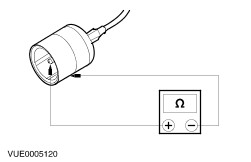
- Handset holder
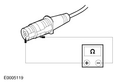
- Cellular phone antenna
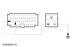
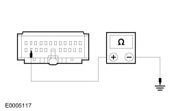
- Portable support electronics (PSE) module
- Audio unit
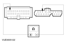
| - If an obvious cause for an observed or reported concern is found, correct the cause (if possible) before proceeding to the next step.
- If the cause is not visually evident, verify the symptom and refer to the Symptom Chart.
Symptom Chart Symptom Chart | Symptom | Possible Sources | Action | | The audio unit display does not display PHONE | * Fuse(s). * Circuit. * Audio unit. * PSE module. | * | | The handset battery does not charge | * Fuse(s). * Circuit. * PSE module. | * | | * Cellular phone battery. | * REFER to the cellular phone Owner's Guide. | | Poor reception, static on calls, frequent drop of calls | * Cellular phone antenna. * Handset holder. | * | | The cellular phone microphone is not operating correctly | * Circuit. * Microphone. | * | | Reduced sound or no sound through the speakers | * Audio unit. * Cellular phone. * Circuit. * PSE module. | * | | The cellular phone information is not displayed | * Cellular phone. * Circuit. * Audio unit. * PSE module. | * | Pinpoint Tests NOTE:Use a digital multimeter for all electrical measurements. | PINPOINT TEST A : THE AUDIO UNIT DISPLAY DOES NOT DISPLAY PHONE | | TEST CONDITIONS | DETAILS/RESULTS/ACTIONS | | A1: CHECK THE AUDIO UNIT FOR CELLULAR PHONE SYMBOL | | | 1 Inspect the audio unit for compatibility. | | | Does the audio unit have a phone symbol after the model number? Yes No INSTALL a new audio unit with a phone symbol. REFER to Section 415-01 Audio Unit. TEST the system for normal operation. | | A2: CHECK THE AUDIO UNIT TO PSE MODULE HARNESS 91S-MD37 | | | 1 Ignition switch in position 0. | | | 2 Disconnect PSE Module C463. | | | 3 Disconnect Audio Unit C447. | | | 4 Measure the resistance between the audio unit C447 pin 4, circuit 91S-MD37 (BK/RD), harness side and the PSE module C463 pin 11, 91S-MD37 (BK/RD), harness side. | | | Is the resistance less than 5 ohms? Yes No REPAIR the circuit . TEST the system for normal operation. | | A3: CHECK FOR VOLTAGE AT THE PSE MODULE | | | 1 Ignition switch in position II. | | | 2 Measure the voltage at the PSE module C463 pin 10, circuit 29-MC9 (OG/BK), harness side and the PSE module C463 pin 8, circuit 75-MC9 (YE/GN), harness side and ground. | | | Are the voltages greater than 10 volts? Yes No REPAIR circuit 29-MC9 (OG/BK) or circuit 75-MC9 (YE/GN). TEST the system for normal operation. | | A4: CHECK GROUND CIRCUIT 91-MC9 (BK/GN) | | | 1 Ignition switch in position 0. | | | 2 Measure the resistance between the PSE module C463 pin 9, circuit 91-MC9 (BK/GN), harness side and ground. | | | Is the resistance less than 5 ohms? Yes No REPAIR the circuit. TEST the system for normal operation. | | A5: CHECK FOR CORRECT OPERATION OF THE AUDIO UNIT | | | 1 Substitute a known good compatible audio unit. | | | 2 Ignition switch in position II. | | | 3 Verify the correct operation of the audio unit. | | | Does the substitute audio unit display PHONE when the cellular phone is installed into the handset holder? Yes REMOVE the substitute audio unit and INSTALL a new audio unit. REFER to Section 415-01 Audio Unit. TEST the system for normal operation. No REMOVE the substitute audio unit and INSTALL a new PSE module. TEST the system for normal operation. | | PINPOINT TEST B : THE HANDSET BATTERY DOES NOT CHARGE | | TEST CONDITIONS | DETAILS/RESULTS/ACTIONS | | B1: CHECK THE CELLULAR PHONE DISPLAY WHEN BEING USED OUTSIDE OF THE VEHICLE | | | 1 Operate the cellular phone outside of the vehicle. | | | Does the cellular phone display low battery? Yes No CHECK the cellular phone battery. REFER to the cellular phone Owner's Guide. | | B2: CHECK THE BATTERY SYMBOL ON CELLULAR PHONE | | | 1 Ignition switch in position II. | | | INSTALL the cellular phone into the handset holder. Does the battery symbol flash? Yes Battery charging correctly. WAIT for the battery to charge. TEST the system for normal operation. No | | B3: CHECK FOR VOLTAGE AT THE PSE MODULE | | | 1 Disconnect PSE Module C463. | | | 2 Measure the voltage between the PSE module C463 pin 10, circuit 29-MC9 (OG/BK), harness side and the PSE module C463 pin 8, circuit 75-MC9 (YE/GN), harness side and ground. | | | Are the voltages greater than 10 volts? Yes No REPAIR circuit 29-MC9 (OG/BK) or circuit 75-MC9 (YE/GN). TEST the system for normal operation. | | B4: CHECK FOR VOLTAGE AT THE HANDSET HOLDER CIRCUIT 8-MC17A | | | 1 Disconnect Handset Holder C471. | | | 2 Measure the voltage between the handset holder C471 pin 10, circuit 8-MC17A (WH/RD), harness side and ground. | | | Is the voltage greater than 10 volts? Yes No NOTE: If the connector is damaged install a new harness. REPAIR the circuit. TEST the system for normal operation. | | B5: CHECK GROUND CIRCUIT 91-MC9 (BK/GN) | | | 1 Measure the resistance between the PSE module C463 pin 9, circuit 91-MC9 (BK/GN), harness side and ground. | | | Is the resistance less than 5 ohms? Yes No REPAIR the circuit. TEST the system for normal operation. | | B6: CHECK GROUND CIRCUIT 91-MC10 (BK/RD) | | | 1 Measure the resistance between the handset holder C471 pin 9, circuit 91-MC10 (BK/RD), harness side and ground. | | | Is the resistance less than 5 ohms? Yes INSTALL a new PSE module. TEST the system for normal operation. No REPAIR the circuit. TEST the system for normal operation. | | PINPOINT TEST C : POOR RECEPTION, STATIC ON CALLS, FREQUENT DROP OF CALLS | | TEST CONDITIONS | DETAILS/RESULTS/ACTIONS | | C1: CHECK THE CELLULAR PHONE FOR SIGNAL STRENGTH OUTSIDE OF THE VEHICLE | NOTE:Check the correct cellular phone network is selected before carrying out any tests. | | | 1 Operate the cellular phone outside of the vehicle. | | | Does the cellular phone display a good signal strength outside of the vehicle? Yes No TEST the system in an area known to have good signal strength. | | C2: CHECK THE CELLULAR PHONE ANTENNA CONNECTION AT THE HANDSET HOLDER | | | 1 Inspect the cellular phone antenna cable connection. | | | Is the cellular phone antenna connected to the handset holder? Yes No RECONNECT the cellular phone antenna. TEST the system for normal operation. | | C3: CHECK THE CELLULAR PHONE ANTENNA HAS BEEN INSTALLED CORRECTLY | | | 1 Inspect the cellular phone antenna. | | | Has the cellular phone antenna been installed correctly on the windshield? REFER to Cellular Phone Antenna - in this section. Yes No INSTALL a new cellular phone antenna correctly. REFER to Cellular Phone Antenna - in this section. TEST the system for normal operation. | | C4: CHECK THE CELLULAR PHONE ANTENNA CABLE FOR SHORT | | | 1 Measure the resistance between the cellular phone antenna center conductor and the cellular phone antenna ground (shield). | | | Is the resistance between 9,000 and 10,000 ohms? Yes No INSTALL a new cellular phone antenna. REFER to Cellular Phone Antenna - in this section. TEST the system for normal operation. | | C5: CHECK THE HANDSET HOLDER CELLULAR PHONE ANTENNA CONNECTION | | | 1 Measure the resistance between the cellular phone antenna center conductor and the antenna ground (shield). | | | Is the resistance between 9,000 and 10,000 ohms? Yes No INSTALL a new cellular phone antenna. REFER to Cellular Phone Antenna - in this section. TEST the system for normal operation. | | C6: CHECK HANDSET HOLDER TO CELLULAR PHONE CONNECTOR | | | 1 Measure the resistance between the handset holder C1026 pin 2, circuit harness side and the handset holder C1026 pin 3, harness side . | | | Is the resistance between 9,000 and 10,000 ohms? Yes CHECK the connection between the cellular phone and the handset holder. TEST the system for normal operation. No INSTALL a new handset holder. REFER to Handset Holder - in this section. TEST the system for normal operation. | | PINPOINT TEST D : THE CELLULAR PHONE MICROPHONE IS NOT OPERATING CORRECTLY | | TEST CONDITIONS | DETAILS/RESULTS/ACTIONS | | D1: CHECK THE VOICE IS BEING TRANSMITTED DURING A TELEPHONE CONVERSION OUTSIDE OF THE VEHICLE | NOTE:Make sure that the cellular phone is a Ford cellular phone. A similar non-Ford phone is not compatible with this system. A Ford cellular phone will display the Ford logo when switched on. | | | 1 Operate the cellular phone outside the vehicle. | | | Does the cellular phone transmit the voice during a telephone conversation outside of the vehicle? Yes No REFER to a Motorola Service Center. TEST the system for normal operation. | | D2: CHECK CIRCUITS 9-MC8A AND 9-MC8 FOR OPEN | | | 1 Disconnect PSE Module. C463. | | | 2 Disconnect Microphone C440. | | | 3 Measure the resistance between the PSE module C463 pin 2, circuit 9-MC8A (BN) (BN/RD for vehicles built 01/2000 onwards), harness side and the microphone C440 pin 1, circuit 9-MC8 (BN), harness side. | | | Is the resistance less than 5 ohms? Yes No REPAIR the circuit. TEST the system for normal operation. | | D3: CHECK CIRCUIT 8-MC8 FOR OPEN | | | 1 Measure the resistance between the PSE module C463 pin 3, circuit 8-MC8 (WH) (WH/RD for vehicles built 01/2000 onwards), and the microphone C440 pin 2, circuit 8-MC8 (WH) (WH/RD for vehicles built 01/2000 onwards), harness side. | | | Is the resistance less than 5 ohms? Yes INSTALL a new microphone. TEST the system for normal operation. No REPAIR the circuit. TEST the system for normal operation. | | PINPOINT TEST E : REDUCED SOUND OR NO SOUND THROUGH THE SPEAKERS | | TEST CONDITIONS | DETAILS/RESULTS/ACTIONS | | E1: CHECK THE CELLULAR PHONE OPERATES CORRECTLY OUTSIDE THE VEHICLE | | | 1 | | | 2 Operate the cellular phone outside the vehicle. | | | Does the cellular phone operate correctly outside the vehicle? Yes No REFER to a Motorola Service Center. TEST the system for normal operation. | | E2: CHECK CIRCUIT 1-MD52 FOR OPEN | | | 1 Disconnect PSE Module C463. | | | 2 Disconnect Audio Unit C447. | | | 3 Measure the resistance between the PSE module C463 pin 21, circuit 1-MD52 (WH/RD), harness side and the audio unit C447 pin 9, circuit 1-MD52 (WH/RD), harness side. | | | Is the resistance less than 5 ohms? Yes No REPAIR the circuit. TEST the system for normal operation. | | E3: CHECK CIRCUIT 8-MD52 FOR OPEN | | | 1 Measure the resistance between the PSE module C463 pin 22, circuit 8-MD52 (WH) (WH/RD for vehicles built 07/2000 onwards), harness side and the audio unit C447 pin 8, circuit 8-MD52 (WH) (WH/RD for vehicles built 07/2000 onwards), harness side. | | | Is the resistance less than 5 ohms? Yes INSTALL a new PSE module. TEST the system for normal operation. No REPAIR the circuit. TEST the system for normal operation. | | PINPOINT TEST F : THE CELLULAR PHONE INFORMATION IS NOT DISPLAYED | | TEST CONDITIONS | DETAILS/RESULTS/ACTIONS | | F1: CHECK CELLULAR PHONE OPERATES CORRECTLY OUTSIDE OF THE VEHICLE | | | 1 Operate the cellular phone outside of the vehicle. | | | Does the cellular phone operate correctly outside of the vehicle? Yes No REFER to a Motorola Service Center. TEST the system for normal operation. | | F2: CHECK CIRCUITS 91S-MC19 AND 91S-MC19A FOR OPEN | | | 1 Disconnect PSE Module C463. | | | 2 Disconnect Handset Holder C471. | | | 3 Measure the resistance between the PSE module C463 pin 20, circuit 91S-MC19 (BK/GN), harness side and the handset holder C471 pin 7, circuit 91S-MC19A (BK/GN), harness side. | | | Is the resistance less than 5 ohms? Yes No REPAIR the circuit. TEST the system for normal operation. | | F3: CHECK CIRCUITS 5-MC20 AND 5-MC20A FOR OPEN | | | 1 Measure the resistance between the PSE module C463 pin 19, circuit 5-MC20 (BU/YE), harness side and the handset holder C471 pin 6, circuit 5-MC20A (BU/YE), harness side. | | | Is the resistance less than 5 ohms? Yes No REPAIR the circuit. TEST the system for normal operation. | | F4: CHECK CIRCUIT 4-MC21 AND 4-MC21A FOR OPEN | | | 1 Measure the resistance between the PSE module C463 pin 18, circuit 4-MC21 (GY/WH), harness side and the handset holder C471 pin 5, circuit 4-MC21A (GY/WH), harness side. | | | Is the resistance less than 5 ohms? Yes No REPAIR the circuit. TEST the system for normal operation. | | F5: CHECK CIRCUIT 5-EA10 FOR OPEN | | | 1 Disconnect Audio Unit C447. | | | 2 Measure the resistance between the PSE module C463 pin 13, circuit 5-EA10 (BN/YE), harness side and the audio unit C447 pin 2, circuit 5-EA10 (BN/YE), harness side. | | | Is the resistance less than 5 ohms? Yes No REPAIR the circuit. TEST the system for normal operation. | | F6: CHECK CIRCUIT 4-EA10 FOR OPEN | | | 1 Measure the resistance between the PSE module C463 pin 12, circuit 4-EA10 (GY/BK), harness side and the audio unit C447 pin 1, circuit 4-EA10 (GY/BK), harness side. | | | Is the resistance less than 5 ohms? Yes No REPAIR the circuit. TEST the system for normal operation. | | F7: CHECK FOR CORRECT OPERATION OF THE AUDIO UNIT | | | 1 Substitute a known good compatible audio unit. | | | 2 Ignition switch in position II. | | | 3 Verify the correct operation of the substitute audio unit. | | | Does the substitute audio unit display phone information when the cellular phone is installed into the handset holder? Yes REMOVE the substitute audio unit and INSTALL a new audio unit. REFER to Section 415-01 Audio Unit. TEST the system for normal operation. No REMOVE the substitute audio unit and INSTALL a new PSE module. TEST the system for normal operation. | |