| Diagnosis and Testing Refer to Wiring Diagrams Section 501-16, for schematic and connector information. Inspection and Verification - Verify the customer concern.
- Visually inspect for obvious signs of mechanical or electrical damage.
Visual Inspection Chart | Mechanical | Electrical | - Wiper blade(s)
- Wiper arm pivot shaft
- Washer reservoir
- Hose(s)
- Washer nozzles
| - Fuse(s)
- Wiring harness
- Electrical connector(s)
- Washer pump(s)
- Wiper motor(s)
| - If an obvious cause for an observed or reported concern is found, correct the cause (if possible) before proceeding to the next step.
- If the concern is not visually evident, verify the symptom and refer to the Symptom Chart.
Symptom Chart Symptom Chart | Symptom | Possible Sources | Action | | No communication with the central timer module (CTM) | * Data bus (ISO 9141) * Central timer module (CTM) | * REFER to: Communications Network - Vehicles Built Up To: 08/2001 (418-00 Module Communications Network, Diagnosis and Testing). | | The wipers are inoperative | * Fuse * Circuit(s) * Windshield wiper relay * Rear window wiper relay * Wiper/washer switch * Windshield wiper motor * Rear window wiper motor * Central timer module (CTM) * Central junction box (CJB) | * | | The wipers stay on continuously | * Circuit(s) * Windshield wiper relay * Rear window wiper relay * Wiper/washer switch * Windshield wiper motor * Rear window wiper motor * Central timer module (CTM) * Central junction box (CJB) | * | | The high/low wiper speed does not operate correctly (intermittent wiper mode OK) | * Circuit(s) * Wiper/washer switch * Windshield wiper motor | * | | The intermittent wiper speed does not operate correctly (high/low speeds OK) | * Circuit(s) * Wiper/washer switch * Windshield wiper relay * Central timer module (CTM) * Central junction box (CJB) | * | | The wash and wipe function are inoperative | * Circuit(s) * Wiper/washer switch * Windshield wiper relay * Central timer module (CTM) * Central junction box (CJB) | * | | The wipers will not park at the correct position | * Circuit(s) * Windshield wiper motor * Rear window wiper motor * Windshield wiper relay * Central timer module (CTM) * Central junction box (CJB) | * | | The one touch wipe function is inoperative | * Wiper/washer switch | * CHECK the wiper/washer switch according to the Component Test attached to this section. If necessary INSTALL a new one. TEST the system for normal operation. | | The wipers do not operate correctly with the WASHER function | * Circuit(s) * Central timer module (CTM) * Central junction box (CJB) | * | | The washer pump is inoperative | * Circuit(s) * Two-way washer pump motor | * | | The variable interval mode does not operate correctly | * Circuit(s) * Wiper/washer switch * Central timer module (CTM) * Central junction box (CJB) | * | | The low washer fluid indicator does not operate correctly | * Circuit(s) * Low washer fluid switch * Trip computer module | * REFER to: Central Timer Module (CTM) - Vehicles Built Up To: 08/2001 (419-10 Multifunction Electronic Modules, Diagnosis and Testing). | | The headlamp washer function does not operate correctly | * Fuse * Circuit(s) * Headlamp washer relay * Headlamp washer pump motor * Battery junction box (BJB) | * | Pinpoint Tests | PINPOINT TEST A : THE WIPERS ARE INOPERATIVE | | TEST CONDITIONS | DETAILS/RESULTS/ACTIONS | | A1: CHECK THE FUSE F55 | | | 1 Ignition switch in position 0. | | | 2 CHECK Fuse F55 (CJB). | | | 3 CHECK the fuse F55 (20 A). | | | Is the fuse OK? Yes No INSTALL a new fuse F55 (20 A). If the fuse blows again, LOCATE and REPAIR the short circuit by using the wiring diagrams. TEST the system for normal operation. | | A2: CHECK THE POWER SUPPLY OF FUSE F55 | | | 1 Connect Fuse F55 (CJB). | | | 2 Ignition switch in position II. | | | 3 Measure the voltage between fuse F55 and ground. | | | Is battery voltage indicated? Yes Vehicles with rear window wipers: GO to A3. Vehicles without rear window wipers: GO to A5. No CHECK the CJB. If necessary INSTALL a new one. TEST the system for normal operation. | | A3: CHECK THE FUSE F43 | | | 1 Ignition switch in position 0. | | | 2 CHECK Fuse F43 (CJB). | | | 3 CHECK the fuse F43 (15 A). | | | Is the fuse OK? Yes No INSTALL a new fuse F43 (15 A). If the fuse blows again, LOCATE and REPAIR the short circuit by using the wiring diagrams. TEST the system for normal operation. | | A4: CHECK THE POWER SUPPLY OF FUSE F43 | | | 1 Connect Fuse F43 (CJB). | | | 2 Ignition switch in position II. | | | 3 Measure the voltage between fuse F43 and ground. | | | Is battery voltage indicated? Yes No CHECK the CJB. If necessary INSTALL a new one. TEST the system for normal operation. | | A5: CHECK THE POWER SUPPLY OF WIPER/WASHER SWITCH | | | 1 CHECK the system by using the WDS. If any DTC's are indicated, work through it. TEST the system for normal operation. If the system is faulty again, follow the next test steps. | | | 2 Ignition switch in position 0. | | | 3 Disconnect Wiper/washer switch C441. | | | 4 Ignition switch in position II. | | | 5 Measure the voltage between wiper/washer switch, connector C441, pin 6, circuit 15-KA19 (GN/OG), harness side and ground. | | | Is battery voltage indicated? Yes The windshield wipers are inoperative: GO to A6. The rear window wipers are inoperative: GO to A8. No REPAIR the open circuit(s) between wiper/washer switch and CJB, connector C17, pin 1, by using the wiring diagrams. TEST the system for normal operation. | | A6: CHECK THE POWER SUPPLY FOR LOW WIPER SPEED TO WINDSHIELD WIPER MOTOR | | | 1 Ignition switch in position 0. | | | 2 Connect Wiper/washer switch C441. | | | 3 Disconnect Windshield wiper motor C848. | | | 4 Ignition switch in position II. | | | 5 Turn the wiper/washer switch to the LOW WIPER SPEED position. | | | 6 Measure the voltage between windshield wiper motor, connector C848, pin 5, circuit 32-KA10 (WH/GN), harness side and ground. | | | Is battery voltage indicated? Yes No CHECK the wiper/washer switch according to the Component Test attached to this section. If necessary INSTALL a new one. TEST the system for normal operation. | | A7: CHECK THE GROUND CONNECTION OF WINDSHIELD WIPER MOTOR | | | 1 Measure the resistance between windshield wiper motor, connector C848, pin 1, circuit 31-KA9 (BK), wiring harness side and ground. | | | Is the resistance less than 2 ohms? Yes CHECK the windshield wiper motor according to the Component Test attached to this section. If necessary INSTALL a new one. TEST the system for normal operation. No REPAIR the open circuit(s) between windshield wiper motor and ground G37, by using the wiring diagrams. TEST the system for normal operation. | | A8: CHECK THE GROUND CONNECTION OF REAR WINDOW WIPER MOTOR | | | 1 Ignition switch in position 0. | | | 2 CHECK the ground connection of rear window wiper motor housing. | | | Is the ground connection OK? Yes No REPAIR the ground connection between rear window wiper motor housing and ground. TEST the system for normal operation. | | A9: CHECK THE POWER SUPPLY OF REAR WINDOW WIPER RELAY | | | 1 Connect Wiper/washer switch C441. | | | 2 Disconnect Rear window wiper relay C1018. | | | 3 Ignition switch in position II. | | | 4 Measure the voltage between rear window wiper relay, socket C1018, pin 5 and ground. | | | Is battery voltage indicated? Yes No CHECK the CJB. If necessary INSTALL a new one. TEST the system for normal operation. | | A10: CHECK THE CONTROL CIRCUIT OF REAR WINDOW WIPER RELAY | | | 1 Measure the voltage between rear window wiper relay, socket C1018, pin 1 and ground. | | | Is battery voltage indicated? Yes No CHECK the CJB. If necessary INSTALL a new one. TEST the system for normal operation. | | A11: CHECK THE REAR WINDOW WIPER RELAY | | | 1 Check the rear window wiper relay according to the Component Test attached to this section. | | | Is the relay OK? Yes No INSTALL a new rear window wiper relay. TEST the system for normal operation. | | A12: CHECK THE CJB | | | 1 Ignition switch in position 0. | | | 2 Connect Rear window wiper relay C1018. | | | 3 Disconnect Central junction box (CJB) C14. | | | 4 Measure the resistance at the CJB, connector C14, between pin 3 and pin 10, CJB side. | | | Is the resistance less than 2 ohms? Yes No CHECK the CJB. If necessary INSTALL a new one. TEST the system for normal operation. | | A13: CHECK THE GROUND CIRCUIT OF REAR WINDOW WIPER RELAY | | | 1 Ignition switch in position 0. | | | 2 Measure the resistance between CJB, connector C14, pin 3, harness side and ground. | | | Is the resistance less than 2 ohms? Yes No REPAIR the open circuit(s) between CJB, connector C14, pin 3 and ground G14, by using the wiring diagrams. TEST the system for normal operation. | | A14: CHECK THE CONTROL CIRCUIT TO CTM FOR REAR WINDOW WIPER | | | 1 Ignition switch in position II. | | | 2 Turn the wiper/washer switch to the REAR WIPER position. | | | 3 Measure the voltage between CJB, connector C14, pin 5, circuit 32-KA35 (WH/RD), harness side and ground. | | | Is battery voltage indicated? Yes No | | A15: CHECK THE WIPER/WASHER SWITCH | | | 1 Ignition switch in position 0. | | | 2 Disconnect Wiper/washer switch C441. | | | 3 Connect a jumper wire at the wiper/washer switch, connector C441, between pin 6, circuit 15-KA19 (GN/OG) and pin 5, circuit 32-KA35 (WH/RD), harness side. | | | 4 Ignition switch in position II. | | | 5 Measure the voltage between CJB, connector C14, pin 5, circuit 32-KA35 (WH/RD), harness side and ground. | | | Is battery voltage indicated? Yes CHECK the wiper/washer switch according to the Component Test attached to this section. If necessary INSTALL a new one. TEST the system for normal operation. No REPAIR the open circuit(s) between CJB, connector C14, pin 5 and wiper/washer switch, by using the wiring diagrams. TEST the system for normal operation. | | A16: CHECK THE CJB | | | 1 Ignition switch in position 0. | | | 2 Disconnect Central timer module (CTM) C1000. | | | 3 Measure the resistance at the CJB between connector C14, pin 5 and CTM, socket C1000, pin 28. | | | Is the resistance less than 2 ohms? Yes No CHECK the CJB. If necessary INSTALL a new one. TEST the system for normal operation. | | A17: CHECK THE CIRCUIT TO REAR WINDOW WIPER MOTOR | | | 1 Connect Central junction box (CJB) C14. | | | 2 Connect Central timer module (CTM) C1000. | | | 3 Disconnect Rear window wiper motor C971. | | | 4 Ignition switch in position II. | | | 5 Measure the voltage between rear window wiper motor, connector C971, pin 1, circuit 15-KA28 (GN/BU), harness side and ground. | | | Is battery voltage indicated? Yes No REPAIR the open circuit(s) between wiper/washer switch and rear window wiper motor, by using the wiring diagrams. TEST the system for normal operation. | | A18: CHECK THE CIRCUIT FOR WIPER PARK TO REAR WINDOW WIPER MOTOR | | | 1 Turn the wiper/washer switch to the REAR WIPER position. | | | 2 Measure the voltage between rear window wiper motor, connector C971, pin 2, circuit 32-KA28 (WH/RD), harness side and ground. | | | Is battery voltage indicated? Yes CHECK the rear window wiper motor according to the Component Test attached to this section, If necessary INSTALL a new one. TEST the system for normal operation. No REPAIR the open circuit(s) between wiper/washer switch and rear window wiper motor, by using the wiring diagrams. TEST the system for normal operation. | | PINPOINT TEST B : THE WIPERS STAY ON CONTINUOUSLY | | TEST CONDITIONS | DETAILS/RESULTS/ACTIONS | | B1: CHECK THE SYSTEM BY USING THE WDS | | | 1 Check the system by using the WDS. | | | Are any DTC's indicated? Yes Work through it. TEST the system for normal operation. No The rear window wipers stay on continuously: GO to B8. The windshield wipers stay on continuously: GO to B2. | | B2: CHECK THE FAULT CONDITION | | | 1 Ignition switch in position 0. | | | 2 Disconnect Windshield wiper relay C1019. | | | 3 Ignition switch in position II. | | | 4 Check the wipers. | | | Stay the wipers on continuously? Yes No | | B3: CHECK THE CONTROL CIRCUIT OF WINDSHIELD WIPER RELAY FOR SHORT TO GROUND | | | 1 Ignition switch in position 0. | | | 2 Measure the resistance between windshield wiper relay, socket C1019, pin 2 and ground. | | | Is the resistance greater than 10 kohm? Yes No CHECK the CJB. If necessary INSTALL a new one. TEST the system for normal operation. | | B4: CHECK THE WINDSHIELD WIPER RELAY | | | 1 CHECK the windshield wiper relay according to the Component Test attached to this section. | | | Is the relay OK? Yes No INSTALL a new windshield wiper relay. TEST the system for normal operation. | | B5: CHECK THE WIPER/WASHER SWITCH FOR PROPER FUNCTION | | | 1 Ignition switch in position 0. | | | 2 Disconnect Wiper/washer switch C441. | | | 3 CHECK the wiper/washer switch according to the Component Test attached to this section. | | | Is the switch OK? Yes REPAIR the short to power, circuit connected with wiper/washer switch, connector C441, pin 10, by using the wiring diagrams. TEST the system for normal operation. No INSTALL a new wiper/washer switch. TEST the system for normal operation. | | B6: DETERMINE THE CONDITION | | | 1 Ignition switch in position 0. | | | 2 Connect Windshield wiper relay C1019. | | | 3 Disconnect Wiper/washer switch C441. | | | 4 Ignition switch in position II. | | | 5 Check the wipers. | | | Stay the wipers on continuously? Yes No CHECK the wiper/washer switch according to the Component Test attached to this section. If necessary INSTALL a new one. TEST the system for normal operation. | | B7: CHECK THE CIRCUIT FOR HIGH WIPER SPEED TO WINDSHIELD WIPER MOTOR | | | 1 Measure the voltage between wiper/washer switch, connector C441, pin 8, circuit 32-KA11 (WH/BK), harness side and ground. | | | Is battery voltage indicated? Yes REPAIR the short to power, circuit connected with the wiper/washer switch, connector C441, pin 8, by using the wiring diagrams. TEST the system for normal operation. No CHECK the windshield wiper motor according to the Component Test attached to this section. If necessary INSTALL a new one. TEST the system for normal operation. | | B8: CHECK THE REAR WINDOW WIPER RELAY | | | 1 Ignition switch in position 0. | | | 2 Disconnect Rear window wiper relay C1018. | | | 3 Ignition switch in position II. | | | 4 Check the wipers. | | | Stay the wipers on continuously? Yes No | | B9: CHECK THE WIPER/WASHER SWITCH | | | 1 Ignition switch in position 0. | | | 2 Connect Rear window wiper relay C1018. | | | 3 Disconnect Wiper/washer switch C441. | | | 4 Ignition switch in position II. | | | 5 Check the wipers. | | | Stay the wipers on continuously? Yes CHECK the rear window wiper motor according to the Component Test attached to this section. If necessary INSTALL a new one. TEST the system for normal operation. No CHECK the wiper/washer switch according to the Component Test attached to this section. If necessary INSTALL a new one. TEST the system for normal operation. | | B10: CHECK THE REAR WINDOW WIPER RELAY FOR PROPER FUNCTION | | | 1 CHECK the rear window wiper relay according to the Component Test attached to this section. | | | Is the relay OK? Yes No INSTALL a new rear window wiper relay. TEST the system for normal operation. | | B11: CHECK THE CONTROL CIRCUIT OF REAR WINDOW WIPER RELAY FOR SHORT TO GROUND | | | 1 Ignition switch in position 0. | | | 2 Measure the resistance between rear window wiper relay, socket C1018, pin 2 and ground. | | | Is the resistance greater than 10 kohms? Yes CHECK the wiper/washer switch according to the Component Test attached to this section. If necessary INSTALL a new one. TEST the system for normal operation. No CHECK the CJB. If necessary INSTALL a new one. TEST the system for normal operation. | | PINPOINT TEST C : THE HIGH/LOW WIPER SPEED DOES NOT OPERATE CORRECTLY (INTERMITTENT WIPER MODE OK) | | TEST CONDITIONS | DETAILS/RESULTS/ACTIONS | | C1: CHECK THE CIRCUIT FOR LOW WIPER SPEED TO WINDSHIELD WIPER MOTOR | | | 1 CHECK the system by using the WDS. If any DTC's are indicated, work through it. TEST for normal operation. If the system is faulty again, follow the next test steps. | | | 2 Ignition switch in position 0. | | | 3 Disconnect Windshield wiper motor C848. | | | 4 Ignition switch in position II. | | | 5 Turn the wiper/washer switch to the LOW WIPER SPEED position. | | | 6 Measure the voltage between windshield wiper motor, connector C848, pin 5, circuit 32-KA10 (WH/GN) and ground. | | | Is battery voltage indicated? Yes No CHECK the wiper/washer switch according to Component Test attached to this section. If necessary INSTALL a new one. TEST the system for normal operation. | | C2: CHECK THE POWER SUPPLY FOR HIGH WIPER SPEED TO WINDSHIELD WIPER MOTOR | | | 1 Turn the wiper/washer switch to the HIGH WIPER SPEED position. | | | 2 Measure the voltage between windshield wiper motor, connector C848, pin 4, circuit 32-KA11 (WH/BK), harness side and ground. | | | Is battery voltage indicated? Yes CHECK the windshield wiper motor according to Component Test attached to this section. If necessary INSTALL a new one. TEST the system for normal operation. No | | C3: CHECK THE CIRCUIT FOR HIGH WIPER SPEED TO WINDSHIELD WIPER MOTOR | | | 1 Ignition switch in position 0. | | | 2 Disconnect Wiper/washer switch C441. | | | 3 Measure the resistance between wiper/washer switch , connector C441, pin 8, circuit 32-KA11 (WH/BK), harness side and windshield wiper motor, connector C848, pin 4, circuit 32-KA11 (WH/BK), harness side. | | | Is the resistance less than 2 ohms? Yes No REPAIR the open circuit(s) between wiper/washer switch and windshield wiper motor, by using the wiring diagrams. TEST the system for normal operation. | | C4: CHECK THE WINDSHIELD WIPER MOTOR FOR PROPER FUNCTION | | | 1 Connect Windshield wiper motor C848. | | | 2 Connect a jumper wire at the wiper/washer switch, connector C441, between pin 6, circuit 15-KA19 (GN/OG) and pin 8, circuit 32-KA11 (WH/BK), harness side. | | | 3 Ignition switch in position II. | | | 4 Check the function of the wipers. | | | Does the windshield wiper motor operate correctly (high wiper speed)? Yes CHECK the wiper/washer switch according to the Component Test attached to this section. If necessary INSTALL a new one. TEST the system for normal operation. No CHECK the windshield wiper motor according to the Component Test attached to this section. If necessary INSTALL a new one. TEST the system for normal operation. | | PINPOINT TEST D : THE INTERMITTENT WIPER SPEED DOES NOT OPERATE CORRECTLY (HIGH/LOW SPEEDS OK) | | TEST CONDITIONS | DETAILS/RESULTS/ACTIONS | | D1: CHECK THE CONTROL CIRCUIT TO WINDSHIELD WIPER RELAY | | | 1 Ignition switch in position 0. | | | 2 Disconnect Windshield wiper relay C1019. | | | 3 Ignition switch in position II. | | | 4 Measure the voltage between windshield wiper relay, socket C1019, pin 1 and ground. | | | Is battery voltage indicated? Yes No CHECK the CJB. If necessary INSTALL a new one. TEST the system for normal operation. | | D2: CHECK THE POWER SUPPLY OF WINDSHIELD WIPER RELAY | | | 1 Measure the voltage between windshield wiper relay, socket C1019, pin 5 and ground. | | | Is battery voltage indicated? Yes No CHECK the CJB. If necessary INSTALL a new one. TEST the system for normal operation. | | D3: CHECK THE CONTROL CIRCUIT OF WINDSHIELD WIPER RELAY FOR SHORT TO POWER | | | 1 Measure the voltage between windshield wiper relay, socket C1019, pin 2 and ground. | | | Is battery voltage indicated? Yes CHECK the CJB. If necessary INSTALL a new one. TEST the system for normal operation. No | | D4: CHECK THE WINDSHIELD WIPER RELAY FOR PROPER FUNCTION | | | 1 Ignition switch in position 0. | | | 2 CHECK the windshield wiper relay according to the Component Test attached to this section. | | | Is the relay OK? Yes No INSTALL a new relay. TEST the system for normal operation. | | D5: CHECK THE POWER SUPPLY FOR INTERMITTENT WIPE TO CTM | | | 1 Connect Windshield wiper relay C1019. | | | 2 CHECK the system by using the WDS. If any DTC's are indicated, work through it. TEST the system for normal operation. If the system is faulty again, follow the next test steps. | | | 3 Ignition switch in position 0. | | | 4 Disconnect Central junction box (CJB) C15. | | | 5 Ignition switch in position II. | | | 6 Turn the wiper/washer switch to the INTERMITTENT WIPE position. | | | 7 Measure the voltage between CJB, connector C15, pin 6, circuit 8-KA19 (WH/BK), harness side and ground. | | | Is battery voltage indicated? Yes CHECK the CJB. If necessary INSTALL a new one. TEST the system for normal operation. No | | D6: CHECK THE WIPER/WASHER SWITCH FOR PROPER FUNCTION | | | 1 Ignition switch in position 0. | | | 2 Disconnect Wiper/washer switch C441. | | | 3 CHECK the wiper/washer switch according to the Component Test attached to this section. | | | Is the switch OK? Yes With variable intermittent wipers: GO to D7. Without variable intermittent wipers: REPAIR the open circuit(s) between CJB, connector C15, pin 6 and wiper/washer switch, by using the wiring diagrams. TEST the system for normal operation. No INSTALL a new wiper/washer switch. TEST the system for normal operation. | | D7: CHECK THE CONTROL CIRCUIT 8-KA18 (WH) TO CTM FOR OPEN | | | 1 Connect Central junction box (CJB) C15. | | | 2 Disconnect Central junction box (CJB) C11. | | | 3 Measure the resistance between CJB, connector C11, pin 15, circuit 8-KA18 (WH), harness side and wiper/washer switch, connector C441, pin 1, circuit 8-KA18 (WH), harness side. | | | Is the resistance less than 2 ohms? Yes No REPAIR the open circuit(s) between CJB, connector C11, pin 15 and wiper/washer switch, by using the wiring diagrams. TEST the system for normal operation. | | D8: CHECK THE CONTROL CIRCUIT 8-KA18 (WH) TO CTM FOR SHORT TO POWER | | | 1 Connect Wiper/washer switch C441. | | | 2 Ignition switch in position II. | | | 3 Turn the wiper/washer switch to the OFF position. | | | 4 Measure the voltage between CJB, connector C11, pin 15, circuit 8-KA18 (WH), harness side and ground. | | | Is battery voltage indicated? Yes REPAIR the short to power, circuit connected with wiper/washer switch, connector C441, pin 1, by using the wiring diagrams. TEST the system for normal operation. No | | D9: CHECK THE CONTROL CIRCUIT 8-KA18 (WH) TO CTM FOR SHORT TO GROUND | | | 1 Ignition switch in position 0. | | | 2 Measure the resistance between CJB, connector C11, pin 15, circuit 8-KA18 (WH), harness side and ground. | | | Is the resistance greater than 10 kohms? Yes CHECK the CJB. If necessary INSTALL a new one. TEST the system for normal operation. No REPAIR the short to ground, circuit(s) connected with wiper/washer switch, connector C441, pin 1, by using the wiring diagrams. TEST the system for normal operation. | | PINPOINT TEST E : THE WASH AND WIPE FUNCTION ARE INOPERATIVE | | TEST CONDITIONS | DETAILS/RESULTS/ACTIONS | | E1: CHECK WITH WDS | | | 1 CHECK the system by using the WDS. | | | Are any DTC's indicated? Yes Work through it. TEST the system for normal operation. No | | E2: CHECK THE CIRCUIT FOR WIPE AND WASH TO CTM | | | 1 Ignition switch in position 0. | | | 2 Disconnect Central timer module (CTM) C1000. | | | 3 Ignition switch in position II. | | | 4 Measure the voltage at the CTM, socket C1000, between pin 27 and pin 17. | | | Is battery voltage indicated? Yes No | | E3: CHECK THE WIPER/WASHER SWITCH FOR PROPER FUNCTION | | | 1 Ignition switch in position 0. | | | 2 Disconnect Wiper/washer switch C441. | | | 3 CHECK the wiper/washer switch according to the Component Test attached to this section. | | | Is the switch OK? Yes REPAIR the open circuit between CTM, connector C1000, pin 27 and wiper/washer switch, by using the wiring diagrams. TEST the system for normal operation. No INSTALL a new wiper/washer switch. TEST the system for normal operation. | | E4: CHECK THE WIPER/WASHER SWITCH FOR PROPER FUNCTION | | | 1 Ignition switch in position 0. | | | 2 Disconnect Wiper/washer switch C441. | | | 3 CHECK the wiper/washer switch according to the Component Test attached to this section. | | | Is the switch OK? Yes No INSTALL a new wiper/washer switch. TEST the system for normal operation. | | E5: CHECK THE CIRCUIT FOR WIPE AND WASH TO WIPER/WASHER SWITCH | | | 1 Connect Wiper/washer switch C441. | | | 2 Ignition switch in position II. | | | 3 Measure the voltage at the CTM, socket C1000, between pin 29 and pin 17. | | | Is battery voltage indicated? Yes REPAIR the open circuit 31-KA19 (BK), between wiper/washer switch and ground G14, by using the wiring diagrams. TEST the system for normal operation. No REPAIR the open circuit 32-KA6 (WH/BK), between wiper/washer switch and splice S14, by using the wiring diagrams. TEST the system for normal operation. | | PINPOINT TEST F : THE WIPERS WILL NOT PARK AT THE CORRECT POSITION | | TEST CONDITIONS | DETAILS/RESULTS/ACTIONS | | F1: DETERMINE THE CONDITION | | | 1 Determine the vehicle equipment. | | | Do the vehicle have rear window wipers? Yes No | | F2: DETERMINE THE FAULT CONDITION | | | 1 Ignition switch in position II. | | | 2 Turn the wiper/washer switch to the REAR WINDOW WIPER position and to the OFF position | | | 3 Check the park position of the wipers. | | | Do the rear window wipers park in the correct position? Yes No CHECK the rear window wiper motor according to the Component Test attached to this section. | | F3: CHECK THE WINDSHIELD WIPER RELAY FOR PROPER FUNCTION | | | 1 Ignition switch in position 0. | | | 2 Disconnect Windshield wiper relay C1019. | | | 3 Connect a jumper wire at the windshield wiper relay, socket C1019, between pin 3 and pin 4. | | | 4 Ignition switch in position II. | | | 5 Actuate the SINGLE WIPE. | | | 6 Check the park position of the wipers. | | | Do the wipers park in the correct position? Yes INSTALL a new windshield wiper relay. TEST the system for normal operation. No | | F4: CHECK THE CONTROL CIRCUIT(S) TO WINDSHIELD WIPER MOTOR | | | 1 Ignition switch in position 0. | | | 2 Connect Windshield wiper relay C1019. | | | 3 Disconnect Windshield wiper motor C848. | | | 4 Measure the resistance at the windshield wiper motor, connector C848, between pin 2, circuit 32-KA9 (WH/BU) and pin 5, circuit 32-KA10 (WH/GN), harness side. | | | Is the resistance less than 2 ohms? Yes No | | F5: CHECK THE POWER SUPPLY FOR WIPER PARK TO WINDSHIELD WIPER MOTOR | | | 1 Ignition switch in position II. | | | 2 Measure the voltage between windshield wiper motor, connector C848, pin 3, circuit 15-KA9 (GN/RD) and ground. | | | Is battery voltage indicated? Yes CHECK the windshield wiper motor according to the Component Test attached to this section. If necessary INSTALL a new one. TEST the system for normal operation. No REPAIR the open circuit(s) between CJB, connector C17, pin 1 and windshield wiper motor, by using the wiring diagrams. TEST the system for normal operation. | | F6: CHECK THE CJB | | | 1 Disconnect Central junction box (CJB) C14. | | | 2 Disconnect Central timer module (CTM) C1000. | | | 3 Disconnect Windshield wiper relay C1019. | | | 4 Measure the resistance at the CJB, between connector C14, pin 9, CJB side and - windshield wiper relay, socket C1019, pin 4.
- CTM, socket C1000, pin 7.
| | | Is the resistance in both measures less than 2 ohms? Yes No CHECK the CJB. If necessary INSTALL a new one. TEST the system for normal operation. | | F7: CHECK THE CIRCUIT TO WINDSHIELD WIPER MOTOR | | | 1 Measure the resistance between CJB, connector C14, pin 9, circuit 32-KA9 (WH/BU), harness side and windshield wiper motor, connector C848, pin 2, circuit 32-KA9 (WH/BU), harness side. | | | Is the resistance less than 2 ohms? Yes No REPAIR the open circuit(s) between CJB, connector C14, pin 9 and windshield wiper motor, by using the wiring diagrams. TEST the system for normal operation. | | F8: CHECK THE WIPER/WASHER SWITCH | | | 1 Disconnect Wiper/washer switch C441. | | | 2 CHECK the wiper/washer switch according to the Component Test attached to this section. If necessary INSTALL a new one. TEST the system for normal operation. | | | Is the wiper/washer switch OK? Yes REPAIR the open circuit 32-KA19 (WH/BK), between wiper/washer switch and windshield wiper relay, by using the wiring diagrams. TEST the system for normal operation. No INSTALL a new wiper/washer switch. TEST the system for normal operation. | | PINPOINT TEST G : THE WIPERS DO NOT OPERATE CORRECTLY WITH THE WASHER FUNCTION | | TEST CONDITIONS | DETAILS/RESULTS/ACTIONS | | G1: CHECK THE CJB | | | 1 CHECK the system by using the WDS. If any DTC's are indicated, work through it. TEST the system for normal operation. If the system is faulty again, follow the next test steps. | | | 2 Ignition switch in position 0. | | | 3 Disconnect Central timer module (CTM) C1000. | | | 4 Disconnect Two-way washer pump motor C828. | | | 5 Ignition switch in position II. | | | 6 Measure the voltage at the CTM, socket C1000, between pin 27 and pin 17. | | | Is battery voltage indicated? Yes No CHECK the CJB. If necessary INSTALL a new one. TEST the system for normal operation. | | G2: CHECK THE CIRCUIT FOR WIPE AND WASH TO CTM | | | 1 Ignition switch in position 0. | | | 2 Disconnect Central junction box (CJB) C14. | | | 3 Ignition switch in position II. | | | 4 Measure the voltage between CJB, connector C14, pin 1, circuit 32-KA6A (WH/BK), harness side and ground. | | | Is battery voltage indicated? Yes CHECK the CJB. If necessary INSTALL a new one. TEST the system for normal operation. No REPAIR the open circuit(s) between CJB, connector C14, pin 1 and splice S14, by using the wiring diagrams. TEST the system for normal operation. | | PINPOINT TEST H : THE WASHER PUMP IS INOPERATIVE | | TEST CONDITIONS | DETAILS/RESULTS/ACTIONS | | H1: CHECK THE CIRCUIT TO WASHER PUMP MOTOR FOR OPEN | | | 1 Ignition switch in position 0. | | | 2 Disconnect Two-way washer pump motor C828. | | | 3 Ignition switch in position II. | | | 4 Measure the voltage between two-way washer pump motor, connector C828, pin 1, circuit 32-KA34 (WH/BK), harness side and ground. | | | Is battery voltage indicated? Yes No REPAIR the open circuit(s) between two-way washer pump motor and splice S14, by using the wiring diagrams. TEST the system for normal operation. | | H2: CHECK THE CIRCUIT TO TWO-WAY WASHER PUMP MOTOR FOR OPEN | | | 1 Measure the voltage between two-way washer pump motor, connector C828, pin 2, circuit 33-KA34 (YE/BK), harness side and ground. | | | Is battery voltage indicated? Yes CHECK the two-way washer pump motor. If necessary INSTALL a new one. TEST the system for normal operation. No REPAIR the open circuit(s) between washer pump motor, connector C828, pin 2 and CJB, by using the wiring diagrams. TEST the system for normal operation. | | PINPOINT TEST I : THE VARIABLE INTERVAL MODE DOES NOT OPERATE CORRECTLY | | TEST CONDITIONS | DETAILS/RESULTS/ACTIONS | | I1: CHECK THE WIPER/WASHER SWITCH FOR PROPER FUNCTION | | | 1 CHECK the system by using the WDS. If any DTC's are indicated, work through it. TEST the system for normal operation. If the system is faulty again, follow the next test steps. | | | 2 Ignition switch in position 0. | | | 3 Disconnect Wiper/washer switch C441. | | | 4 CHECK the wiper/washer switch according to the Component Test attached to this section. | | | Is the switch OK? Yes No INSTALL a new wiper/washer switch. TEST the system for normal operation. | | I2: CHECK THE CIRCUIT FOR VARIABLE INTERMITTENT WIPE TO CTM | | | 1 Disconnect Central junction box (CJB) C11. | | | 2 Measure the resistance between CJB, connector C11, pin 15, circuit 8-KA18 (WH), harness side and wiper/washer switch, connector C441, pin 1, circuit 8-KA18 (WH), harness side. | | | Is the resistance less than 2 ohms? Yes No REPAIR the open circuit(s) between CJB, connector C11, pin 15 and wiper/washer switch, by using the wiring diagrams. TEST the system for normal operation. | | I3: CHECK THE CIRCUIT FOR VARIABLE INTERMITTENT WIPE TO CTM FOR SHORT TO POWER | | | 1 Connect Wiper/washer switch C441. | | | 2 Ignition switch in position II. | | | 3 Turn the wiper/washer switch to the OFF position. | | | 4 Measure the voltage between CJB, connector C11, pin 15, circuit 8-KA18 (WH), harness side and ground. | | | Is battery voltage indicated? Yes REPAIR the short to power, circuit(s) connected with wiper/washer switch, connector C441, pin 1, by using the wiring diagrams. TEST the system for normal operation. No | | I4: CHECK THE CIRCUIT FOR VARIABLE INTERMITTENT WIPE TO CTM FOR SHORT GROUND | | | 1 Ignition switch in position 0. | | | 2 Measure the resistance between CJB, connector C11, pin 15, circuit 8-KA18 (WH), harness side and ground. | | | Is the resistance greater than 10 kohms? Yes CHECK the CJB. If necessary INSTALL a new one. TEST the system for normal operation. No REPAIR the short to ground, circuit(s) connected with wiper/washer switch, connector C441, pin 1, by using the wiring diagrams. TEST the system for normal operation. | | PINPOINT TEST J : THE HEADLAMP WASHER FUNCTION DOES NOT OPERATE CORRECTLY | | TEST CONDITIONS | DETAILS/RESULTS/ACTIONS | | J1: CHECK THE POWER SUPPLY OF HEADLAMP WASHER RELAY | | | 1 Ignition switch in position 0. | | | 2 Disconnect Headlamp washer relay C1004. | | | 3 Ignition switch in position II. | | | 4 Measure the voltage between headlamp washer relay, socket C1004, pin 2 and ground. | | | Is battery voltage indicated? Yes No | | J2: CHECK THE FUSE F13 | | | 1 Ignition switch in position 0. | | | 2 CHECK Fuse F13 (BJB). | | | 3 CHECK the fuse F13 (30 A). | | | Is the fuse OK? Yes No INSTALL a new fuse F13 (30 A). If the fuse blows again, LOCATE and REPAIR the short circuit by using the wiring diagrams. TEST the system for normal operation. | | J3: CHECK THE POWER SUPPLY OF FUSE F13 | | | 1 Ignition switch in position II. | | | 2 Measure the voltage between fuse F13 (BJB) and ground. | | | Is battery voltage indicated? Yes No CHECK the BJB. If necessary INSTALL a new one. TEST the system for normal operation. | | J4: CHECK THE CONTROL CIRCUIT (HEADLAMP ON) TO HEADLAMP WASHER RELAY | | | 1 Ignition switch in position 0. | | | 2 Connect Fuse F13 (BJB). | | | 3 Ignition switch in position II. | | | 4 Turn the light switch to the LOW BEAM position. | | | 5 Measure the voltage between headlamp washer relay, socket C1004, pin 5 and ground. | | | Is battery voltage indicated? Yes No REPAIR the open circuit(s) between light switch and headlamp washer relay, by using the wiring diagrams. TEST the system for normal operation. | | J5: CHECK THE GROUND CONNECTION OF HEADLAMP WASHER RELAY | | | 1 Turn the light switch to the OFF position. | | | 2 Ignition switch in position 0. | | | 3 Measure the resistance between headlamp washer relay, socket C1004, pin 1 and ground. | | | Is the resistance less than 2 ohms? Yes No REPAIR the open circuit(s) between headlamp washer relay and ground G37, by using the wiring diagrams. TEST the system for normal operation.. | | J6: CHECK THE CIRCUIT FOR WASHER ON TO THE HEADLAMP WASHER RELAY | | | 1 Ignition switch in position II. | | | 2 Measure the voltage between headlamp washer relay, socket C1004, pin 3, circuit 32-KA22 (WH/RD) and ground. | | | Is battery voltage indicated? Yes No REPAIR the open circuit(s) between headlamp washer relay, connector C1004, pin 3 and splice S14, by using the wiring diagrams. TEST the system for normal operation. | | J7: CHECK THE HEADLAMP WASHER PUMP. | | | 1 Connect Headlamp washer relay C1004. | | | 2 Disconnect Headlamp washer pump motor C745. | | | 3 Ignition switch in position II. | | | 4 Turn the light switch to the LOW BEAM position. | | | 5 Actuate the WINDSHIELD WASHER during the measurement. | | | 6 Measure the voltage between headlamp washer pump motor, connector C745, pin 1, circuit 15S-KA21 (GN/YE), harness side and ground. | | | Is battery voltage indicated? Yes No REPAIR the open circuit between headlamp washer relay, connector C1004, pin 4 and headlamp washer pump motor, by using the wiring diagrams. TEST the system for normal operation. | | J8: CHECK THE GROUND CONNECTION OF HEADLAMP WASHER PUMP | | | 1 Ignition switch in position 0. | | | 2 Measure the resistance between headlamp washer pump motor, connector C745, pin 2, circuit 31-KA21 (BK), harness side and ground. | | | Is the resistance less than 2 ohms? Yes CHECK the headlamp washer pump motor. If necessary INSTALL a new one. TEST the system for normal operation. No REPAIR the open circuit(s) between headlamp washer pump motor and ground G37, by using the wiring diagrams. TEST the system for normal operation. | Component Test Windshield wiper motor - Switch the ignition OFF.
- Disconnect the connector.
- Using a test cable and set up the test as in the following description.
- Using an external 12V DC supply which can be loaded to at least 10 Amps, or use fused battery voltage.
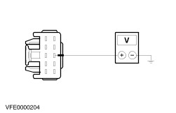
- Check the wiper motor in LOW WIPER SPEED condition
- Connect the power supply positive terminal with the positive terminal of the digital multimeter.
- Connect the power supply negative terminal with the wiper motor, pin 1.
- Connect the digital multimeter negative terminal with the wiper motor, pin 5. The wiper motor will run at slow speed.
Measure the amperage. Is the value at the digital multimeter next to 1,5 A? If yes, GO to 2. If no, INSTALL a new windshield wiper motor. - Check the wiper motor in HIGH WIPER SPEED condition (figure VFE0002216)
- Connect the power supply positive terminal with the positive terminal of the digital multimeter.
- Connect the power supply negative terminal with the wiper motor, pin 1.
- Connect the digital multimeter negative terminal with the wiper motor, pin 4. The wiper motor will run at fast speed.
Measure the amperage. Is the value at the digital multimeter next to 2,2 A? If yes, GO to 3. If no, INSTALL a new windshield wiper motor. - Check the wiper motor in WIPER PARK position
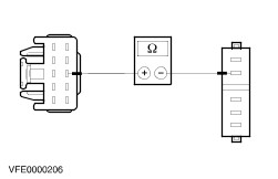
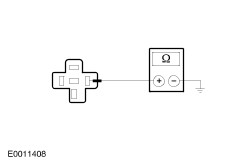
Measure the resistance at the windshield wiper motor, between pin 2 and wiper motor housing. Is the resistance less than 2 ohms? If yes, GO to 4. If no, GO to 4. and REPEAT this teststep (If no again, INSTALL a new windshield wiper motor). - Check the WIPER PARK function of the wiper motor
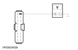
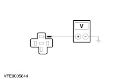
- Connect the power supply positive terminal with wiper motor, pin 5.
- Connect the power supply negative terminal with wiper motor, pin 2.
- Connect a jumper wire with the wiper motor, between pin 1 and pin 3.
Determine the condition Does the wiper motor move to the WIPER PARK position? If yes, the windshield wiper motor is OK. If no, INSTALL a new windshield wiper motor. Rear window wiper motor - Switch the ignition OFF.
- Disconnect the connector.
- Using a test cable and set up the test as in the following description.
- Using an external 12V DC supply which can be loaded to at least 10 Amps, or use fused battery voltage.
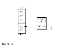
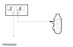
- Check the wiper motor in ON condition.
- Connect the power supply positive terminal with the positive terminal of the digital multimeter.
- Connect the power supply negative terminal with the wiper motor housing.
- Connect the digital multimeter negative terminal with the wiper motor, pin 2. The wiper motor will run.
Measure the amperage. Is the value at the digital multimeter next to 1,5 A? If yes, GO to 2. If no, INSTALL a new rear window wiper motor. - Check the WIPER PARK function of the wiper motor
- Connect the power supply positive terminal with the wiper motor, pin 1.
- Connect the power supply negative terminal with the wiper motor housing.
Determine the condition. Does the wiper motor move to the WIPER PARK position? If yes, the rear window wiper motor is OK. If no, INSTALL a new rear window wiper motor. Relays - Windshield wiper relay
- Rear window wiper relay
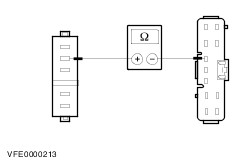
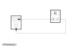
- Check the relay contact in normal condition (closed position)
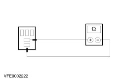
Measure the resistance at the relay between pin 3 and pin 4. Is the resistance less than 1 ohm? If yes, go to step 2. If no, INSTALL a new relay. - Check the relay contact in normal condition (open position)
Measure the resistance at the relay between pin 3 and pin 5. Is the resistance greater than 10 kohms? If yes, go to step 3. If no, INSTALL a new relay. - Check relay contact in activated condition (closed position)
Using a test cable and set up the test as in the following description. - Connect the battery positive terminal with the relay, pin 1.
- Connect the battery negative terminal with the relay, pin 2.
Measure the resistance at the relay between pin 3 and pin 5. Does the relay switch (audible click) when battery voltage is applied and is the resistance less than 1 ohm? If yes, the relay is OK. If no, INSTALL a new relay. Wiper/washer switch | Function to check | Pins to connect with the digital multimeter | Switch setting | Target values | | INTERMITTENT WIPE | 6 and 10 | one-touch | greater than 10 kohms | | | | off | greater than 10 kohms | | | | intermittent | less than 1 ohm | | | | slow speed | greater than 10 kohms | | | | fast speed | greater than 10 kohms | | | 7 and 9 | one-touch | greater than 10 kohms | | | | off | less than 1 ohm | | | | intermittent | less than 1 ohm | | | | slow speed | greater than 10 kohms | | | | fast speed | greater than 10 kohms | | | 1 and 6 | one-touch | greater than 10 kohms | | | | off | greater than 10 kohms | | | | intermittent | Refer to variable intermittent wipe | | | | slow speed | greater than 10 kohms | | | | fast speed | greater than 10 kohms | | VARIABLE INTERMITTENT WIPE | 1 and 10 | 1 | 1 kohm | | | | 2 | 10 kohms | | | | 3 | 20 kohms | | | | 4 | 30 kohms | | | | 5 | 40 kohms | | | | 6 | 47 kohms | | ONE TOUCH WIPE | 6 and 9 | one-touch | less than 1 ohm | | | | off | greater than 10 kohms | | | | intermittent | greater than 10 kohms | | | | slow speed | greater than 10 kohms | | | | fast speed | greater than 10 kohms | | LOW WIPER SPEED | 6 and 9 | one-touch | greater than 10 kohms | | | | off | greater than 10 kohms | | | | intermittent | greater than 10 kohms | | | | slow speed | less than 1 ohm | | | | fast speed | greater than 10 kohms | | high wiper speed | 6 and 8 | one-touch | greater than 10 kohms | | | | off | greater than 10 kohms | | | | slow speed | greater than 10 kohms | | | | slow speed | greater than 10 kohms | | | | fast speed | less than 1 ohm | | WINDSHIELD WASHER | 2 and 6 | off | less than 1 ohm | | | | on | greater than 10 kohms | | | 2 and 3 | off | greater than 10 kohms | | | | on | less than 1 ohm | | REAR WINDOW WASHER | 3 and 5 | off | less than 1 ohm | | | | rear window wiper | greater than 10 kohms | | | | rear window washer | greater than 10 kohms | | | 4 and 6 | off | less than 1 ohm | | | | rear window wiper | less than 1 ohm | | | | rear window washer | greater than 10 kohms | | | 3 and 4 | off | greater than 10 kohms | | | | rear window wiper | greater than 10 kohms | | | | rear window washer | less than 1 ohm | | | 5 and 6 | off | greater than 1 ohm | | | | rear window wiper | less than 1 ohm | | | | rear window washer | less than 1 ohm | |