The supplemental restraint system (SRS) has been specifically designed to protect the driver and passenger, from sustaining severe facial and upper body injuries in the event of a serious impact. Optimum protection can only be achieved when used in conjunction with a conventional three-point safety belt. The safety belts form an integral part of the SRS.
1
-
AIRBAG logo embossed onto the seat cover
The driver, wearing the safety belt provided, should position the seat as far back as is practical, so the steering wheel can be reached with arms slightly angled, thereby leaving a gap between the steering wheel and the driver.
The front passenger, wearing the safety belt provided, should not position himself or herself so that the air bag cover is in direct contact with the occupants’ body.
The front air bags and safety belt buckle pretensioners will deploy, in the event of an impact that exceeds the deployment threshold, either by a direct front impact or when the impact angle is up to 30 degrees from the left or right of the vehicle center line.
The air bag(s) and safety belt buckle pretensioners will deploy only once. In a collision in which they deployed at the first impact, the air bag(s) and safety belt pretensioners will not reduce the risk of injury in a subsequent impact.
In the event of a side impact, in which the side air bags (if equipped) deploy, the front air bags will still deploy in a subsequent front impact, provided that the front impact exceeds the triggering threshold.
Under certain circumstances, although the damage sustained by the vehicle may look extensive, the impact may remain below the triggering threshold of the SRS and the air bags will not deploy. In such circumstances the safety belts would provide sufficient protection for the occupants.
The visible VIN plate, which shows the air bag symbol and either X1, X2 or X4 dependent on the number of air bags fitted, is attached to the windshield edge of the instrument panel.
Vehicles equipped with side air bags can be identified by an embossed AIRBAG logo on the seat fabric adjacent to the air bag module. A label is attached to the B - pillar adjacent to the seat.
WARNING:All vehicles fitted with the passenger air bag from the factory have a WARNING sticker attached to the instrument panel, PROHIBITING the use of rear facing child or baby seats.
It is not possible under any circumstances to disable the passenger air bag while maintaining the integrity of the whole SRS.
The SRS consists of the following components:
- air bag control module
- wiring harness
- clockspring
- warning indicator
- air bag module(s)
- side impact sensors (vehicles with side air bags)
- safety belt buckle and pretensioners
Air Bag Control Module
The air bag control module governs the operation of the whole system, including the diagnostic element. It contains two frontal impact micro machine sensors; a crash sensor and a safing sensor. These two sensors are connected in series and if they both sense a deceleration in excess of a predetermined limit, the air bag control module will deploy the air bag module(s).
The air bag control module will also deploy the corresponding side air bag module dependent on the signal received from the side impact sensor.
The air bag control module also carries out continual system diagnostics. In the event of a fault being detected the warning indicator is illuminated either constantly or intermittently. The behavior of the warning indicator depends on the type of fault present. The warning indicator is located in the instrument cluster.
A new air bag control module must be installed following a collision in which the safety belt pretensioners or air bag(s) are deployed.
Safety Belt Buckle and Pretensioner
The safety belt buckle pretensioners are deployed simultaneously by the air bag control module, even if the passenger seat is unoccupied.
In the event of a collision in which the air bag module(s) deploy, the safety belt buckle pretensioners will also deploy. New safety belt buckle and pretensioners must be installed following deployment.
The wiring harness provides power to the air bag control module from the vehicle supply and hence to the air bag module(s), side impact sensors (if equipped with side air bags), safety belt buckle and pretensioners and the warning indicator.
Clockspring
The clockspring is designed to carry signals between the air bag control module and the driver air bag module. The clockspring is fitted to the steering column, and consists of fixed and moving parts connected by a coiled Mylar tape with integral conducting tracks. The Mylar tape is able to ``wind up" and ``unwind" as the steering wheel (to which the moving part is attached) is turned, maintaining electrical contact at all times between the air bag control module and the driver air bag module. The clockspring is used in order to achieve the high degree of circuit integrity required by such a critical safety system as the SRS.
It is advisable to renew the clockspring following a driver air bag deployment.
The side impact sensors (if equipped) are located on the floor panel under the front seats to facilitate lateral impact sensing. In the event of a side impact the air bag control module processes the crash data sent by the side impact sensor. The air bag control module will deploy the side air bag, in the event of an impact which exceeds the deployment threshold, on the side the deployment request was initiated.
A new side impact sensor must be installed following a side impact in which a side air bag deploys.
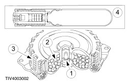
The driver, passenger and side air bag modules consist of the following components, which cannot be disassembled:
4
-
Passenger inflator unit
The inflator is screwed into a high strength plastic cup shaped container. The air bag is then folded on top of the inflator and the whole subassembly is enclosed by the cover.
The driver air bag module is fitted to the steering wheel, the cover forming the outer surface of the steering wheel boss. The cover has invisible ``split lines" moulded in its surfaces allowing the air bag to easily exit through the cover when the system deploys.
A new steering wheel, driver air bag module and wiring harness with the air bag module electrical connectors must be installed following deployment.
The passenger air bag module is located above the glove compartment and is integrated into the instrument panel top to provide an unobtrusive appearance. On vehicles built up to 10/2001 the cover is a one piece moulding attached to the instrument panel by retaining clips and the air bag module by a retaining strap along the windshield edge. On vehicles built from 10/2001 the cover is a one piece moulding attached to the instrument panel by retaining clips and the air bag module by a fixed hinge along the windshield edge. As the air bag deploys, the cover is forced free of the retainers, but remains attached to the instrument panel along its upper edge.
A new front passenger air bag module and wiring harness with the air bag module electrical connectors must be installed following deployment.
Side Air Bag Modules
The side air bag module(s) are integrated into the front seat backrests providing an unobtrusive appearance. The unique seat cover has been designed to accommodate air bag deployment. When the side air bag is deployed the stitched seam of the seat cover adjacent to the side air bag module splits, allowing the air bag to exit the seat backrest unobstructed.
It is recommended that a new seat be installed following a side air bag deployment.
The purpose of the inflator is to generate the gas needed to fill the air bag. It consists of a high strength steel casing filled with a solid propellant charge and an electrically activated igniter. The igniter is activated by a signal from the air bag control module, which in turn ignites the propellant charge. The very rapid burning of the propellant produces sufficient gas to fill the air bag(s). Filling of the passenger and side air bags is augmented by the expansion of stored gas. As the gases expand they cool, preventing heat damage to the bag. The drivers air bag module has one inflator and bag, with a filled volume of 50 litres. The passenger air bag module has one inflator and bag having a filled volume of 100 litres. The side air bag has a single inflator and a bag with a filled volume of 12 litres.
When the air bag(s) deploy, they remain fully inflated for only a fraction of a second and start to deflate immediately, cushioning the occupant. The high speed of inflation, along with the surrounding events and noise from the impact, can give the impression that the air bag(s) did not deploy to their full extent.
The driver air bag is a one-piece woven item, the passenger and side air bags are sewn items. The air bags have a silicon coating to provide flame and heat protection in the vicinity of the inflator. The shape of the passenger and side air bag (if equipped) are tailored to the vehicle proportions.
In order to prevent the folds of the air bag from sticking together in its tightly stowed position, the fabric may be treated with talcum powder. When the air bag(s) deploy, some of the fine powder is blown into the vehicle. This powder is visible as a dust cloud and also has a characteristic odor. The particles soon settle and do not represent a health risk. The dust cloud is not a sign of external combustion outside the air bag inflator cartridge.
In certain circumstances slight grazing or minor friction burns can result from an air bag deployment.
There are two processes which are involved:
- Friction can occur between the fabric of the air bag and the unprotected areas of the skin, either during its very rapid deployment or when the occupant contacts the air bag.
- Hot gases from the charge used to inflate the air bag vent as it starts to deflate. Depending on the position of the drivers hands, or how close the occupant is to the air bag, it is not always possible to exclude the possibility of these gases contacting the areas of skin unprotected by clothing.
The supplemental restraint system will communicate concerns during a driving cycle or after initial key ON by means of a warning indicator located in the instrument cluster.