The bodywork of the Focus is a completely new development. No body parts have been transferred or modified from existing vehicles.
The lock plate and the crossmember are totally new constructions. The fenders are bolted to the bodywork.
Brazed joints
All Focus model variants are without brazed joints.
High-strength low alloy steel parts
High-strength steel parts are used on all of the Focus models.
NOTE:The working methods given in the chapter 501-25A must be observed when performing repairs.
NVH measures
In order to prevent air conduction of noise to the vehicle interior, NVH elements are installed in the cowl panel of the Focus at the A- and B-pillars as well as at the D-pillar of the estate. The NVH elements consist of a carrier plate with a compressed insulation material at the edges. During dip coating, the body is heated to approx. 170° C. At this temperature, the insulation material expands, completely sealing the gap between the carrier plate and the bodywork.
NOTE:When carrying out repair work, NVH elements must be reinstalled or replaced. Missing or defective NVH elements may lead to excessive engine or road noise in the vehicle interior.
NVH measures
Restoring the NVH measures
In order to restore the NVH measures, the NVH elements are installed without insulation material during repairs. Sealing is performed using 1-component body sealant after completion of the repair. The carrier plates are clipped to the inner braces or inner panels in the pillar areas. If the carrier plate is undamaged, the NVH element may be reused; if the carrier plate is damaged, the NVH element must be replaced.
Replace complete NVH element:
- Make the necessary cuts and cut the welded joints.
NOTE:Gases harmful to health will be released if the insulation material is heated excessively.
- Detach the NVH element from the body part to be removed by heating and remove the body part.
- Detach the NVH element with a suitable cutting tool and remove.
- Degrease the body part in the NVH area; prime and paint if necessary.
Overview of parts, floor pan (estate)
The high-strength steel parts are indicated with arrows.
Corrosion prevention measures
All body parts are zinc-plated on all Focus models, with the exception of the roof panel. Furthermore, additional corrosion prevention measures have been carried out.
NOTE:The original corrosion protection must be re-established when working on the bodywork.
Corrosion prevention measures
The following notes regarding body repairs and alternative repair techniques for MIG soldered joints made in production must be observed.
General repair notes
NOTE: All welded joints must be made in accordance with the original condition with regard to type and length of the weld seam.
All joints made during production using the MIG soldering process must be replaced by alternative MIG repair solutions during repairs. Consequently, the soldered joints made during production remain intact in their original condition in the repair method described.
Replacement of a MIG soldered joint with a MIG weld seam at the location the original joint is not permissible. Significant welding problems and joint defects can occur in the weld seam, as complete removal of the old solder cannot be ensured.
MIG soldered joints on the quarter panel
Overview of MIG soldered joints on the quarter panel
1
-
Soldered joints on the sill panel/quarter panel
2
-
Soldered joint on the B-pillar
3
-
Soldered joint on the C-pillar
MIG soldered joint on the sill panel/quarter panel
The cut must be made behind the inner reinforcement, at least 80 mm behind the MIG soldered seam.
NOTE:In the event of damage in the area of the MIG soldered seam or the inner reinforcement, the complete reinforcement area must be removed. Sectional replacement of the sill panel is also necessary.
2
-
Cut location for repairs
NOTE:In the event of damage in the area of the MIG soldered seam, the complete area must be replaced. Sectional replacement of the B- or C-pillar is also necessary.
The offset flanges in the area of the B- or C-pillar are cut from the new part. The old and new parts are butted together and joined with a continuous MIG weld.
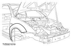
Rear wheel arch flare
If only the wheel arch flare is damaged, it is detached from the inner quarter panel at the original joints and removed.
Installation is carried out in reverse order. When fitting and fastening the wheel arch flare, the outer quarter panel must be installed to serve as a reference plane.
In the event of more severe damage, the inner quarter panel can also be replaced. In this case, the inner quarter panel of the 3-door Focus must be installed and the necessary cutout made subsequently in the area of the wheel arch for the Focus RS wheel arch flare.
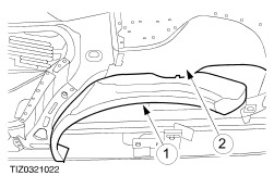
Reinforcement plate for front suspension strut mounting
On the Focus RS, the reinforcement plates in the area of the upper suspension strut mountings must additionally be welded in when replacing the front wheelhouses.
Suspension strut mounting reinforcement plate
Align the reinforcements with the lower reinforcements already installed and weld with an intermittent MIG weld seam.
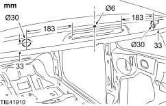
Reinforcement plate for rear axle mounting
In the event of damage to the area of the rear axle mounting, additional reinforcement plates must be welded in on the Focus RS.
Reinforcement plate for rear axle mounting
Align the reinforcements with the existing holes and weld with an intermittent MIG weld seam.
Left-hand engine mounting reinforcement
The left-hand engine mounting is reinforced by means of two additional plates on the Focus RS. It must be reinstalled accordingly during repair. The reinforcement plates must be welded in with an intermittent MIG weld seam.
Left-hand engine mounting reinforcement (viewed from below)