ford Workshop Repair Guides

Ford Workshop Service and Repair Manuals

Electronic Engine Controls - 1.8L Duratec-HE (MI4)-2.0L Duratec-HE (MI4) > < 303-14A Electronic Engine Controls|Specifications
Electronic Engine Controls - Electronic Engine Controls—1.6L Duratec-16V Ti-VCT (Sigma) Focus 2004.75 (07/2004-)
Description and Operation

 
Item
Part Number
Description
1
-
Catalyst Monitor Sensor and Heated Oxygen (HO2S) Sensors
2
-
Camshaft Position (CMP) Sensor
3
-
Powertrain Control Module (PCM)
4
-
Engine Coolant Temperature (ECT) Sensor
5
-
Crankshaft Position (CKP) Sensor
6
-
Variable Camshaft Timing (VCT) Oil Control Solenoid

Catalyst Monitor Sensors HO2S Sensors

The catalyst monitor sensors and H02S sensors are located before and after the catalytic converter. The H02S sensor measures the amount of oxygen in the exhaust system before the catalytic converter. The catalyst monitor sensor measures the amount of oxygen in the exhaust system after the gases have passed through the catalytic converter. Both the catalyst monitor and H02S sensors communicate information to the PCM. The PCM can then make adjustments to the air/fuel ratio and ignition timing.

CMP Sensors

The CMP sensors are located on the top of the valve cover either side of the camshafts. The CMP sensors send signals to the PCM which are then used by the PCM to calculate the position of the camshafts and operate the VCT oil control solenoids.

PCM Module

The Powertrain Control Module is housed within the engine compartment located inside a compartment which is part of the battery tray. The PCM is a Siemens Sim 28 control unit. It has one connection for the wiring harness. The PCM communicates to all engine sensors and electrical components. Communications between the PCM and the diagnosis of the system take place on the CAN databus. Each of the units connected to the CAN databus makes its data available on the databus, providing all participants with equal access to the information.

ECT Sensor

The ECT sensor is located in the coolant connector which is bolted to the cylinder head below the ignition coil pack. The ECT sensor is a resistor with a negative temperature coefficient (NTC resistor). Using the voltage drop across the ECT sensor, the PCM calculates the coolant temperature and can operate the electronic thermostat and cooling fan motor accordingly.

CKP Sensor

The CKP sensor is attached to the engine block. The CKP sensor detects a magnetic disc with 58+2 magnetic pole pairs on it, arranged around the circumference of the flywheel. The CKP sensor uses the Hall effect principle and communicates the information of the crankshaft position to the PCM.

VCT Oil Control Solenoid

The VCT oil control solenoids are located on the top of the valve cover either side of the camshafts. The function of a VCT oil control solenoid is to advance and Retard the camshaft timing in an engine equipped with dual equal camshaft timing phaser. This effect will increase engine power and performance and it also reduces the unburned hydrocarbons and oxides of nitrogen emitted to the exhaust system.

Throttle Position (TP) Sensor

The electronic throttle valve receives an input signal from the PCM. Depending on the operating state of the engine, a change in the position of the throttle plate may not be necessary when the acellerator pedal position (APP) sensor position changes. An electric motor moves the throttle valve shaft by means of a set of gears. The throttle valve position is continuously measured by the TP sensors, and the information about the position is processed and monitored by the PCM. If one of the two TP sensors is faulty, the signal from the intake sensor is used. However, the torque is limited by the PCM. The system switches into an emergency running mode in the event of a defect on both TP sensors, on the throttle valve motor, or if the intact sensor cannot be detected. In this emergency running mode the current supply to the electric throttle valve motor is interrupted. Instead, the throttle valve is closed by means of a spring against a spring-loaded end stop. With the throttle valve position kept constant, the ignition angle and the injected fuel quantity are then varied to meet the torque demands. The stop screw incorporates a spring-loaded pin which enables the throttle valve to be closed beyond the emergency running position (e.g. for idle control or deceleration fuel shut-off). If the difference between the TP sensor values is very great, the larger of the two values is taken to bring the emergency running mode into play. Here again the maximum torque is limited by the PCM. Whenever emergency running mode is selected a diagnostic trouble code (DTC) is stored in the PCM. These codes can be read out with WDS.

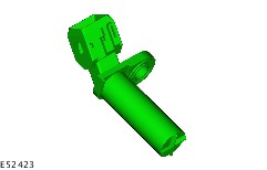
Mass air flow (MAF) sensor

The MAF sensor is located on the outlet side of the air filter housing and operates by using with the hot-wire principle. The signal is used by the PCM to regulate the quantity of air flow. The MAF sensor is also equipped with an integral intake air temperature (IAT) sensor which also enables the intake air temperature to be calculated.

Electronic Engine Controls - 1.8L Duratec-HE (MI4)-2.0L Duratec-HE (MI4) > < 303-14A Electronic Engine Controls|Specifications