| Removal and Installation CAUTION:Never swap the GEM between two vehicles. CAUTION:Compare the number of relays and fuses in the defective GEM and the new GEM. Transfer from the defective GEM any relays and fuses which are not in the new GEM. In doing so, pay attention that fuses with the correct Ampere rating are used, by referring to the wiring diagrams. CAUTION:When installing a new GEM on vehicles with daytime running lamps, make sure that fuses F110 (10A) and F113 (10A) are fitted as part of the repair. CAUTION:When installing a new GEM on vehicles with electrically folding exterior mirrors and on vehicles with an alarm system horn with integral battery, make sure that fuses F137 (10A) are fitted as part of the repair. CAUTION:When installing a new GEM on vehicles with a petrol engine, make sure that fuse F111 (15A) and relay R19 are fitted as part of the repair. CAUTION:When installing a new GEM on vehicles built from 03/2007, make sure that the revised fuse designation is provided in the Owner's Handbook. NOTE:The GEM is integrated into the central junction box (CJB) and cannot be removed individually. | | -
NOTE:This step only needs to be carried out when changing the GEM. Read the vehicle-specific data from the GEM using the diagnostic tester.
For additional information, refer to: Programmable Module Installation (418-01 Module Configuration, General Procedures).
| | | -
NOTE:This operation is only required on vehicles with low equipment levels. Remove the passenger's side footwell trim. | | | -
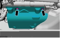
NOTE:This operation is only required on vehicles with high equipment levels. Remove the passenger's side footwell trim. | 4. Remove the components in the order indicated in the following illustration(s) and table(s). 3 - Instrument panel wiring harness connector 5 - Overhead console wiring harness connector 5. To install, reverse the removal procedure. | | -
Programme the GEM.
For additional information, refer to: Programmable Module Installation (418-01 Module Configuration, General Procedures).
| | | -
NOTE:This operation is only required on vehicles with remote control and without the keyless vehicle system. Program the remote control receiver with the diagnostic tester. | | | -
Program remote transmitter.
For additional information, refer to: Remote Transmitter Programming (501-14 Handles, Locks, Latches and Entry Systems, General Procedures).
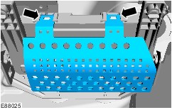
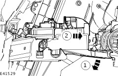
| Removal Details Item 2 : CJB | | -
Detach the CJB from the CJB bracket. - Turn the CJB downwards.
- Remove the CJB.
| Item 4 : Engine wiring harness connector NOTE:On vehicles built from 01/2007, the position of the engine wiring loom connector (C100) changes from the underside of the GEM to the top side. |