
Seats
- Make
- Ford
- Model
- Focus Factory Service Manual
- Year
- 2007
- Section
- 501-10 Seating › Diagnosis and testing › Seats
Seats
Principles of Operation — Heated Seats
The driver and passenger heated seats share a common ignition feed to the heated seat switches and have separate grounds to the backrest heated seat elements. The heated seat switches are a latching type switch; continuity through the switch will remain whether voltage is supplied to the switch or not until the OFF position is selected. When the heated seat switch is pressed and the ignition switch is in the RUN or START position, voltage is supplied to a bi-metallic switch type thermostat that is part of the cushion heated seat element. The cushion and backrest heated seat elements are wired in series and powered by the same output of the thermostat. Each heated seat switch shows ON and OFF status through its own LED indicator. The heated seat will remain ON until the heated seat switch is pressed to OFF and voltage is no longer supplied to the thermostat. If the ignition source is removed (key OFF), the heated seat will return to an ON state once the ignition source is returned (key RUN) and continue to operate until the heated seat switch is pressed to OFF. The heated seat system is designed to heat the seat to 40°C (104°F) and maintain the temperature by the opening (no voltage to the heated seat elements) and closing (voltage supplied to the heated seat elements) of the thermostat.
Inspection and Verification
- Verify the customer concern by operating the manual seat assembly or heated seat system.
- Visually inspect for the following obvious signs of mechanical and electrical damage.
| Mechanical | Electrical |
|---|---|
|
|
- If an obvious cause for an observed or reported concern is found, correct the cause (if possible) before proceeding to the next step.
- If the cause is not visually evident, verify the symptom and GO to Symptom Chart.
Symptom Chart
| Condition | Possible Sources | Action |
|---|---|---|
|
|
|
|
|
|
Pinpoint Tests
WARNING: Always wear safety glasses when repairing an air bag supplemental restraint system (SRS) vehicle and when handling an airbag module. This will reduce the risk of injury in the event of an accidental deployment.
WARNING: Never probe the connectors on the air bag module. Doing so can result in air bag deployment, which can result in personal injury.
Refer to Inspection and Verification and the Symptom Chart for direction to the appropriate Pinpoint Test.
Pinpoint Test A: The Heated Seat Is Inoperative
Refer to Wiring Diagrams Cell 119, Climate Controlled Seats for schematic and connector information.
Normal Operation
The driver and passenger heated seat switches share common ignition voltage feed to circuit 15-HC1 (GN/BU) spliced to the driver heated seat switch circuit 15-HC6 (GN/YE) and the passenger heated seat switch circuit 15-HC9 (GN/BK). The heated seat switches share spliced ground to circuits 31-LH29 (BK) (driver) and 31-LH43 (BK) (passenger). The heated seat switches are a latching style switch with an LED ON/OFF indicator. Continuity through the switch will remain whether voltage is supplied to it or not until switched OFF. With the ignition switch in RUN or START and a heated seat switch in the ON position, voltage is applied to circuit 15S-HC6 (GN/YE) (driver) or 15S-HC9 (GN/BK) (passenger) and connected to a 2-lead bi-metallic switch type thermostat incorporated into each cushion's heated seat element. Each thermostat is connected by a series circuit to the cushion heated seat element internally. Each seat's cushion and backrest heated seat elements are also connected by a series circuit to ground circuit 31-HC8 (BK) (driver) or 31-HC11 (BK) (passenger). With a heated seat switch ON, the cushion thermostat will cycle OPEN or CLOSED to allow current flow to the heated seat elements and regulate the seat cushion temperature at approximately 40°C (104°F). If a heated seat is ON and the ignition source voltage is removed, the heated seat will enter an OFF state but will return ON when the ignition voltage is restored. The temperature sensor is not a serviceable item and must be installed as part of a new cushion heated seat element.
Possible Causes
An inoperative heated seat can be caused by:
- an open fuse.
- circuit 15-HC1 (GN/BU) open.
- circuit 15-HC6 (GN/YE) open.
- circuit 15-HC9 (GN/BK) open.
- circuit 15S-HC6 (GN/YE) open.
- circuit 15S-HC9 (GN/BK) open.
- circuit 31-LH29 (BK) open.
- circuit 31-LH43 (BK) open.
- circuit 31-HC8 (BK) open.
- circuit 31-HC11 (BK) open.
- a faulty heated seat switch.
- a faulty heated seat element.
- a faulty heated seat temperature sensor.
PINPOINT TEST A: THE HEATED SEAT IS INOPERATIVE
NOTE: Connectors for seats with side air bags shown, connectors for seats without side air bags similar.
| Test Step | Result / Action to Take |
|---|---|
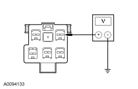
| A1 CHECK FOR VOLTAGE TO THE AFFECTED SEAT ELECTRICAL CONNECTOR | |
|
Yes GO to A4. No GO to A2. |
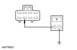
| A2 CHECK FOR VOLTAGE TO THE AFFECTED HEATED SEAT SWITCH | |
|
Yes GO to A3. No VERIFY the central junction box (CJB) fuse 52 (15A) is OK. If OK, REPAIR circuit 15-HC6 (GN/YE) or circuit 15-HC9 (GN/BK). DISCONNECT the battery ground cable. CONNECT the affected seat connector C311 (driver) or C312 (passenger). REPOWER the SRS. REFER to Section 501-20B. TEST the system for normal operation. |
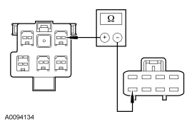
| A3 CHECK CIRCUIT 15S-HC6 (GN/YE) OR CIRCUIT 15S-HC9 (GN/BK) FOR AN OPEN | |
|
Yes INSTALL a new heated seat switch. DISCONNECT the battery ground cable. CONNECT the affected seat connector C311 (driver) or C312 (passenger). REPOWER the SRS. REFER to Section 501-20B. TEST the system for normal operation. No REPAIR circuit 15S-HC6 (GN/YE) or circuit 15S-HC9 (GN/BK). DISCONNECT the battery ground cable. CONNECT the affected seat connector C311 (driver) or C312 (passenger). REPOWER the SRS. REFER to Section 501-20B. TEST the system for normal operation. |
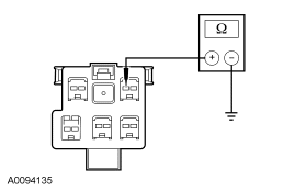
| A4 CHECK CIRCUIT 31-HC8 (BK) OR CIRCUIT 31-HC11 (BK) FOR AN OPEN | |
|
Yes GO to A5. No REPAIR circuit 31-HC8 (BK) or circuit 31-HC11 (BK). DISCONNECT the battery ground cable. CONNECT the affected seat connector C311 (driver) or C312 (passenger). REPOWER the SRS. REFER to Section 501-20B. TEST the system for normal operation. |
| A5 CHECK THE SEAT BACKREST HEATED SEAT ELEMENT FOR CONTINUITY | |
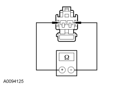
|
Yes INSTALL a new cushion heated seat element. DISCONNECT the battery ground cable. CONNECT the affected seat connector C311 (driver) or C312 (passenger). REPOWER the SRS. REFER to Section 501-20B. TEST the system for normal operation. No INSTALL a new backrest heated seat element. DISCONNECT the battery ground cable. CONNECT the affected seat connector C311 (driver) or C312 (passenger). REPOWER the SRS. REFER to Section 501-20B. TEST the system for normal operation. |
Parts & tools for this job For 2007 Ford Focus
- TOOLTrim removal tool kitSearch: trim removal tool kit
- PARTTouch-up paintSearch: Ford touch up paint
- PARTPanel clip assortmentSearch: Ford panel clips assortment
Links open Amazon search results in a new tab. As an Amazon Associate I earn from qualifying purchases.