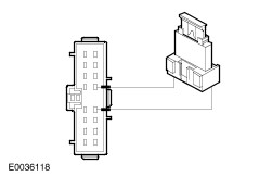
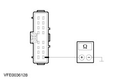
| Diagnosis and Testing Refer to Wiring Diagrams Section 417-01, for schematic and connector information. Special Tool(s) | | Terminal probe kit 29-011A | Inspection and Verification - Verify the customer concern.
- Visually inspect for obvious signs of mechanical or electrical damage.
Visual Inspection Chart | Electrical | - Fuse(s)
- Bulb(s)
- Electrical connector(s)
- Wiring harness
| - If an obvious cause for an observed or reported concern is found, correct the cause (if possible) before proceeding to the next step.
- If the concern is not visually evident, verify the symptom and refer to the Symptom Chart.
Symptom Chart Symptom Chart | Symptom | Possible Sources | Action | | Parking, rear and license lamp(s) are inoperative | * Fuse(s) * Circuit(s) * Light switch * Central junction box (CJB) | * | | One or more parking, rear or license lamp(s) are inoperative | * Fuse(s) * Circuit(s) * Headlamp * Rear lamp assembly * License plate lamp * Light switch * Central junction box (CJB) | * | | The parking, rear or license lamps are on continuously | * Circuit(s) * Light switch * Central junction box (CJB) * Generic electronic module (GEM) | * | Pinpoint Tests | PINPOINT TEST A : PARKING, REAR AND LICENSE LAMP(S) ARE INOPERATIVE | | TEST CONDITIONS | DETAILS/RESULTS/ACTIONS | | A1: DETERMINE THE FAULT CONDITION | | | 1 Switch on the PARK LIGHT. | | | 2 Switch on the PARKING LIGHT. | | | 3 Check the parking, rear and license lamps. | | | Are all parking, rear and license lamp(s) inoperative in park light position? Yes No -All parking and rear lamps are inoperative in parking light position, without day time running lamps: GO to A5. -All parking and rear lamps are inoperative in parking light position, with day time running lamps: GO to A8. -The parking and rear lamps, right-hand side are inoperative: GO to A9. -The parking and rear lamps, left-hand side are inoperative: GO to A10. -The license plate lamps are inoperative: GO to A11. -Both rear lamps are inoperative: LOCATE and REPAIR the open in circuit 31-DA18 (BK), between splice S184 and ground G46 by using the wiring diagrams. TEST the system for normal operation. | | A2: CHECK FUSE F30 (CJB) | | | 1 Ignition switch in position 0. | | | 2 Disconnect Fuse F30 (CJB). | | | 3 CHECK Fuse F30 (10 A) (CJB). | | | Is the fuse OK? Yes No INSTALL a new fuse F30 (10 A) and TEST the system. If the fuse blows again, LOCATE and REPAIR the short to ground by using the wiring diagrams. TEST the system for normal operation. | | A3: CHECK THE VOLTAGE AT FUSE F30 (CJB) | | | 1 Connect Fuse F30 (CJB). | | | 2 Measure the voltage between fuse F30 (CJB) and ground. | | | Is battery voltage indicated? Yes No REPAIR the power supply of fuse F30 (CJB) by using the wiring diagrams. TEST the system for normal operation. INSTALL a new CJB. TEST the system for normal operation. | | A4: CHECK THE POWER SUPPLY OF THE LIGHT SWITCH | | | 1 Disconnect Light switch from connector C320. | | | 2 Measure the voltage between light switch, connector C320, pin 11, circuit 29-LE29 (OG/BK), harness side and ground. | | | Is battery voltage indicated? Yes CHECK the light switch, if necessary INSTALL a new one. TEST the system for normal operation. No LOCATE and REPAIR the open in circuit(s) between fuse F30 (CJB) and light switch by using the wiring diagrams. TEST the system for normal operation. | | A5: CHECK THE POWER SUPPLY OF THE LIGHT SWITCH | | | 1 Ignition switch in position 0. | | | 2 Disconnect Light switch from connector C320. | | | 3 Measure the voltage between light switch, connector C320, pin 12, circuit 30S-LE29 (RD/GN), harness side and ground. | | | Is battery voltage indicated? Yes No | | A6: CHECK THE CIRCUIT 30S-LE29 (RD/GN) FOR OPEN | | | 1 Disconnect Ignition switch from connector C456. | | | 2 Measure the resistance between ignition switch, connector C456, pin 2, circuit 30S-LE29 (RD/GN), harness side and light switch, connector C320, pin 12, circuit 30S-LE29 (RD/GN), harness side. | | | Is the resistance less than 2 ohms? Yes CHECK the ignition switch, if necessary INSTALL a new one. TEST the system for normal operation. No LOCATE and REPAIR the open in circuit(s) between ignition switch and light switch by using the wiring diagrams. TEST the system for normal operation. | | A7: CHECK THE LIGHT SWITCH | | | 1 Connect a fused jumper wire (15 A) at the light switch, connector C320, between pin 12, circuit 30S-LE29 (RD/GN), harness side and pin 13, circuit 29S-LF1 (OG/YE), harness side. | | | 2 Check the parking lamps. | | | Are the parking lamps illuminated? Yes CHECK the light switch, if necessary INSTALL a new one. TEST the system for normal operation. No LOCATE and REPAIR the open in circuit(s) between light switch and fuse F57/F58 (CJB) by using the wiring diagrams. TEST the system for normal operation. | | A8: CHECK THE POWER SUPPLY OF THE LIGHT SWITCH | | | 1 Ignition switch in position 0. | | | 2 Disconnect Light switch from connector C320. | | | 3 Ignition switch in position II. | | | 4 Measure the voltage between light switch, connector C320, pin 15, circuit 15S-LE29 (GN/BK), harness side and ground. | | | Is battery voltage indicated? Yes CHECK the light switch, if necessary INSTALL a new one. TEST the system for normal operation. No LOCATE and REPAIR the open in circuit 15S-LE29(A) (GN/BK) between light switch, connector C320, pin 4 and pin 15 by using the wiring diagrams. TEST the system for normal operation. If the concern is not rectified:REFER to Section 417-04 Daytime Running Lamps (DRL). | | A9: CHECK FUSE F57 (CJB) | | | 1 Ignition switch in position 0. | | | 2 Disconnect Fuse F57 (CJB). | | | 3 CHECK Fuse F57 (7.5 A) (CJB). | | | Is the fuse OK? Yes Connect Fuse F57 (CJB). CHECK the CJB, if necessary INSTALL a new one. TEST the system for normal operation. No INSTALL a new fuse F57 (7.5 A) and TEST the system. If the fuse blows again, LOCATE and REPAIR the short to ground by using the wiring diagrams. TEST the system for normal operation. | | A10: CHECK FUSE F58 (CJB) | | | 1 Ignition switch in position 0. | | | 2 Disconnect Fuse F58 (CJB). | | | 3 CHECK Fuse F58 (7.5 A) (CJB). | | | Is the fuse OK? Yes Connect Fuse F58 (CJB). CHECK the CJB, if necessary INSTALL a new one. TEST the system for normal operation. No INSTALL a new fuse F58 (7.5 A) and TEST the system. If the fuse blows again, LOCATE and REPAIR the short to ground by using the wiring diagrams. TEST the system for normal operation. | | A11: CHECK FUSE F62 (CJB) | | | 1 Ignition switch in position 0. | | | 2 Disconnect Fuse F62 (CJB). | | | 3 CHECK Fuse F62 (7.5 A) (CJB). | | | Is the fuse OK? Yes No INSTALL a new fuse F62 (7.5 A). TEST the system. If the fuse blows again, LOCATE and REPAIR the short to ground by using the wiring diagrams. TEST the system for normal operation. | | A12: CHECK THE VOLTAGE AT FUSE F62 (CJB) | | | 1 Connect Fuse F62 (CJB). | | | 2 Switch on the PARK LIGHT. | | | 3 Measure the voltage between fuse F62 (CJB) and ground. | | | Is battery voltage indicated? Yes No | | A13: CHECK THE VOLTAGE AT THE LICENSE PLATE LAMP LEFT-HAND SIDE | | | 1 Disconnect License plate lamp left-hand side from connector C495. | | | 2 Switch on the PARK LIGHT. | | | 3 Measure the voltage between license plate lamp left-hand side, connector C495, pin 1, circuit 29S-LF21 (OG/BK), harness side and ground. | | | Is battery voltage indicated? Yes REPAIR the open circuit 31-DA13(A) (BK) between splice S196 and ground G35/G15 by using the wiring diagrams. TEST the system for normal operation. No LOCATE and REPAIR the open in circuit(s) between fuse F62 (CJB) and license plate lamp left-hand side by using the wiring diagrams. TEST the system for normal operation. If necessary INSTALL a new CJB. TEST the system for normal operation. | | A14: CHECK THE CIRCUIT 29S-LF5 (OG/BU) FOR OPEN | | | 1 Disconnect Light switch from connector C320. | | | 2 Disconnect Central Junction Box (CJB) from connector C15. | | | 3 Measure the resistance between light switch, connector C320, pin 16, circuit 29S-LF5 (OG/BU), harness side and CJB, connector C15, pin 10, circuit 29S-LF5 (OG/BU), harness side. | | | Is the resistance less than 2 ohms? Yes CHECK the light switch according to the component test, if necessary INSTALL a new one. TEST the system for normal operation. If the concern is not rectified CHECK the CJB and if necessary INSTALL a new one. TEST the system for normal operation. No LOCATE and REPAIR the open in circuit(s) between light switch and CJB by using the wiring diagrams. TEST the system for normal operation. | | PINPOINT TEST B : ONE OR MORE PARKING, REAR OR LICENSE LAMP(S) IS/ARE INOPERATIVE | | TEST CONDITIONS | DETAILS/RESULTS/ACTIONS | | B1: DETERMINE THE FAULT CONDITION | | | 1 Ignition switch in position 0. | | | 2 Switch on the PARK LIGHT. | | | 3 Switch on the PARKING LIGHT. | | | 4 Check the parking, rear and license lamps. | | | Is the parking lamp, front, left-hand side inoperative? Yes No -The parking lamp, front, right-hand side is inoperative GO to B4. -The tail lamp left-hand side is inoperative GO to B6. -The tail lamp right-hand side is inoperative GO to B8. -The license plate lamp, left-hand side is inoperative: GO to B10. -The license plate lamp, right-hand side is inoperative: GO to B11. | | B2: CHECK THE POWER SUPPLY OF THE HEADLAMP LEFT-HAND SIDE | | | 1 Disconnect Headlamp left-hand side from connector C836. | | | 2 Switch on the PARKING LIGHT. | | | 3 Measure the voltage between headlamp left-hand side, connector C836, pin 4, circuit 29S-LF7 (OG/BU), harness side and ground. | | | Is battery voltage indicated? Yes No LOCATE and REPAIR the open in circuit 29S-LF7 (OG/BU) between CJB and headlamp by using the wiring diagrams. TEST the system for normal operation. | | B3: CHECK THE GROUND SUPPLY OF THE HEADLAMP LEFT-HAND SIDE | | | 1 Measure the resistance between headlamp left-hand side, connector C836, pin 6, circuit 31-LE31 (BK), harness side and ground. | | | Is the resistance less than 2 ohms? Yes CHECK the headlamp, if necessary INSTALL a new one. TEST the system for normal operation. No LOCATE and REPAIR the open in circuit 31-LE31 (BK), between headlamp and splice S121 by using the wiring diagrams. TEST the system for normal operation. | | B4: CHECK THE POWER SUPPLY OF THE HEADLAMP RIGHT-HAND SIDE | | | 1 Disconnect Headlamp right-hand side from connector C837. | | | 2 Switch on the PARKING LIGHT. | | | 3 Measure the voltage between headlamp right-hand side, connector C837, pin 4, circuit 29S-LF16 (OG/GN) harness side and ground. | | | Is battery voltage indicated? Yes No LOCATE and REPAIR the open in circuit 29S-LF16 (OG/GN), between CJB and headlamp by using the wiring diagrams. TEST the system for normal operation. | | B5: CHECK THE GROUND SUPPLY OF THE HEADLAMP RIGHT-HAND SIDE | | | 1 Measure the resistance between headlamp right -hand side, connector C837, pin 6, circuit 31-LE30 (BK), harness side and ground. | | | Is the resistance less than 2 ohms? Yes CHECK the headlamp, if necessary INSTALL a new one. TEST the system for normal operation. No LOCATE and REPAIR the open in circuit 31-LE30 (BK), between headlamp and splice S109 by using the wiring diagrams. TEST the system for normal operation. | | B6: CHECK THE VOLTAGE AT THE LAMP ASSEMBLY LEFT REAR | | | 1 Ignition switch in position 0. | | | 2 Disconnect Lamp assembly left rear from connector C472. | | | 3 Switch on the PARKING LIGHT. | | | 4 Measure the voltage between lamp assembly left, rear, connector C472, pin 1, circuit 29S-LF11 (OG/WH), harness side and ground. | | | Is battery voltage indicated? Yes No LOCATE and REPAIR the open in circuit 29S-LF11 (OG/WH) between CJB and lamp assembly by using the wiring diagrams. TEST the system for normal operation. | | B7: CHECK THE GROUND SUPPLY OF THE LAMP ASSEMBLY LEFT REAR | | | 1 Measure the resistance between lamp assembly left, rear, connector C472, pin 3, circuit 31-LF23 (BK), harness side and ground. | | | Is the resistance less than 2 ohms? Yes CHECK the rear lamp assembly, if necessary INSTALL a new one. TEST the system for normal operation. No LOCATE and REPAIR the open in circuit 31-LF23 (BK), between lamp assembly and splice S184 by using the wiring diagrams. TEST the system for normal operation. | | B8: CHECK THE VOLTAGE AT THE LAMP ASSEMBLY RIGHT REAR | | | 1 Ignition switch in position 0. | | | 2 Disconnect Lamp assembly right rear from connector C473. | | | 3 Switch on the PARKING LIGHT. | | | 4 Measure the voltage between lamp assembly right, rear, connector C473, pin 1, circuit 29S-LF20 (OG), harness side and ground. | | | Is battery voltage indicated? Yes No LOCATE and REPAIR the open in circuit 29S-LF20 (OG) between CJB and lamp assembly by using the wiring diagrams. TEST the system for normal operation. | | B9: CHECK THE GROUND SUPPLY OF THE LAMP ASSEMBLY LEFT REAR | | | 1 Measure the resistance between lamp assembly right, rear, connector C473, pin 3, circuit 31-LF24 (BK), harness side and ground. | | | Is the resistance less than 2 ohms? Yes CHECK the rear lamp assembly, if necessary INSTALL a new one. TEST the system for normal operation. No LOCATE and REPAIR the open in circuit 31-LF24 (BK) between lamp assembly and splice S184 by using the wiring diagrams. TEST the system for normal operation. | | B10: CHECK THE GROUND CONNECTION OF THE LICENSE PLATE LAMP LEFT-HAND SIDE | | | 1 Disconnect License plate lamp left-hand side from connector C494. | | | 2 Turn off the PARKING LIGHT. | | | 3 Measure the resistance between license plate lamp left-hand side, connector C494, pin 1, circuit 31-LF21 (BK), harness side and ground. | | | Is the resistance less than 2 ohms? Yes CHECK the license plate lamp, if necessary INSTALL a new one. TEST the system for normal operation. No LOCATE and REPAIR the open in circuit 31-LF21 (BK) between license plate lamp and splice S196 by using the wiring diagrams. TEST the system for normal operation. | | B11: CHECK THE VOLTAGE AT THE LICENSE PLATE LAMP RIGHT-HAND SIDE | | | 1 Ignition switch in position 0. | | | 2 Disconnect License plate lamp right-hand side from connector C497. | | | 3 Switch on the PARKING LIGHT. | | | 4 Measure the voltage between license plate lamp right-hand side, connector C497, pin 1, circuit 29S-LF22 (OG/BK), harness side and ground. | | | Is battery voltage indicated? Yes No LOCATE and REPAIR the open in circuit 29S-LF22 (OG/BK) between license plate lamp left-hand side and license plate lamp right-hand side by using the wiring diagrams. TEST the system for normal operation. | | B12: CHECK THE GROUND CONNECTION OF THE LICENSE PLATE LAMP RIGHT-HAND SIDE | | | 1 Disconnect License plate lamp right-hand side from connector C496. | | | 2 Turn off the PARK LIGHT. | | | 3 Measure the resistance between license plate lamp right-hand side, connector C496, pin 1, circuit 31-LF22 (BK), harness side and ground. | | | Is the resistance less than 2 ohms? Yes CHECK the license plate lamp, if necessary INSTALL a new one. TEST the system for normal operation. No LOCATE and REPAIR the open in circuit 31-LF22 (BK) between license plate lamp and splice S196 by using the wiring diagrams. TEST the system for normal operation. | | PINPOINT TEST C : THE PARKING, REAR OR LICENSE LAMPS ARE ON CONTINUOUSLY | | TEST CONDITIONS | DETAILS/RESULTS/ACTIONS | | C1: DETERMINE THE FAULT CONDITION | | | 1 Ignition switch in position 0. | | | 2 Disconnect Light switch from connector C320. | | | 3 Ignition switch in position II. | | | 4 Check the parking, rear and license lamps. | | | Are any parking, rear or license lamps on continuously? Yes -The license lamps are on continuously: GO to C2. -The parking/rear lamps are on continuously: GO to C4. No CHECK the light switch, if necessary INSTALL a new one. TEST the system for normal operation. | | C2: ISOLATE THE SHORT TO POWER CIRCUIT | | | 1 Ignition switch in position 0. | | | 2 Disconnect Fuse F62 (CJB). | | | 3 Ignition switch in position II. | | | 4 Check the license lamps. | | | Do the license plate lamps illuminate continuously? Yes LOCATE and REPAIR the short to power in circuit(s) connected with the license lamp, connector C495, pin 1 by using the wiring diagrams. TEST the system for normal operation. If necessary CHECK the CJB and INSTALL a new one. TEST the system for normal operation. No | | C3: ISOLATE THE SHORT TO POWER | | | 1 Ignition switch in position 0. | | | 2 Connect Fuse F62 (CJB). | | | 3 Disconnect Fuse F63 (CJB). | | | 4 Disconnect Fuse F32 (CJB). | | | 5 Ignition switch in position II. | | | 6 Check the license plate lamps. | | | Do the license plate lamps illuminate continuously? Yes LOCATE and REPAIR the short to power in circuit(s) connected with the light switch, connector C320, pin 16 by using the wiring diagrams. TEST the system for normal operation. If necessary CHECK the CJB and INSTALL a new one. TEST the system for normal operation. No CHECK the Generic electronic module (GEM) and if necessary INSTALL a new one. TEST the system for normal operation. | | C4: ISOLATE THE SHORT TO POWER CIRCUIT | | | 1 Ignition switch in position 0. | | | 2 Disconnect Fuse F57 (CJB). | | | 3 Disconnect Fuse F58 (CJB). | | | 4 Ignition switch in position II. | | | 5 Check the parking lamps. | | | Are the parking lamps left-hand side illuminated continuously? Yes LOCATE and REPAIR the short to power in circuit(s) connected with fuse F58 (CJB), out by using the wiring diagrams. TEST the system for normal operation. If necessary CHECK the CJB and INSTALL a new one. TEST the system for normal operation. No -The parking lamps right-hand side are on continuously: LOCATE and REPAIR the short to power in circuit(s) connected with fuse F57 (CJB), out by using the wiring diagrams. TEST the system for normal operation. If necessary CHECK the CJB and INSTALL a new one. TEST the system for normal operation. -No parking lamps are illuminated: LOCATE and REPAIR the short to power in circuit 29S-LF1 (OG/YE) between light switch and fuses F58/F57 (CJB) by using the wiring diagrams. TEST the system for normal operation. If necessary CHECK the CJB and INSTALL a new one. TEST the system for normal operation. | |