| PINPOINT TEST B : ONE OR MORE STOPLAMPS ARE INOPERATIVE |
| TEST CONDITIONS | DETAILS/RESULTS/ACTIONS |
| B1: DETERMINE THE FAULT CONDITION |
| | 1 Ignition switch in position II. |
| | 2 Switch on the STOPLAMPS. |
| | 3 Check the stoplamps. |
| | Is the high mounted stoplamp inoperative? Yes No |
| B2: CHECK THE HIGH MOUNTED STOPLAMP |
| | 1 Ignition switch in position 0. |
| | 2 Disconnect High mounted stoplamp from connector C107. |
| | 3 Ignition switch in position II. |
| | 4 Switch on the STOPLAMPS. |
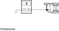
| | 5 Measure the voltage between high mounted stoplamp, connector C107, pin 1, circuit 15S-LG6 (GN/YE), harness side and ground. |
| | Is battery voltage indicated? Yes LOCATE and REPAIR the open in circuit(s) between high mounted stoplamp and ground G35/G15 by using the wiring diagrams. If necessary INSTALL a new high mounted stoplamp. TEST the system for normal operation No LOCATE and REPAIR the open in circuit between splice S154 and high mounted stoplamp by using the wiring diagrams. If necessary INSTALL a new high mounted stoplamp. TEST the system for normal operation. |
| B3: DETERMINE THE FAULT CONDITION |
| | 1 Switch on the STOPLAMPS. |
| | 2 Check the stoplamps. |
| | Are both stoplamps inoperative? Yes No -Left-hand side is inoperative: GO to B5. -Right-hand side is inoperative: GO to B6. |
| B4: CHECK THE COMMON POWER SUPPLY OF THE STOPLAMPS |
| | 1 Ignition switch in position 0. |
| | 2 Disconnect Rear lamp assembly left-hand side from connector C472. |
| | 3 Ignition switch in position II. |
| | 4 Switch on the STOPLAMPS. |
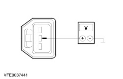
| | 5 Measure the voltage between rear lamp assembly, left-hand side, connector C472, pin 2, circuit 15S-LG14A (GN/RD), harness side and ground. |
| | Is battery voltage indicated? Yes LOCATE and REPAIR the open in circuit 31-DA18 (BK) between splice S184 and ground G46 by using the wiring diagrams. TEST the system for normal operation. No LOCATE and REPAIR the open in circuit 15S-LG14 (GN/RD) between splice S154 and splice S116 (rear lamp assemblies) by using the wiring diagrams. TEST the system for normal operation. |
| B5: CHECK THE POWER SUPPLY OF THE REAR LAMP ASSEMBLY LEFT-HAND SIDE |
| | 1 Ignition switch in position 0. |
| | 2 Disconnect Rear lamp assembly left-hand side from connector C472. |
| | 3 Ignition switch in position II. |
| | 4 Switch on the STOPLAMPS. |
| | 5 Measure the voltage between rear lamp assembly, left-hand side connector C472, pin 2, circuit 15S-LG14A (GN/RD), harness side and ground. |
| | Is battery voltage indicated? Yes LOCATE and REPAIR the open in circuit 31-LF23 (BK) between rear lamp assembly and splice S184 by using the wiring diagrams. If necessary INSTALL a new rear lamp assembly. TEST the system for normal operation. No LOCATE and REPAIR the open in circuit between splice S116 and rear lamp assembly by using the wiring diagrams. If necessary INSTALL a new rear lamp assembly. TEST the system for normal operation. |
| B6: CHECK THE POWER SUPPLY OF THE REAR LAMP ASSEMBLY RIGHT-HAND SIDE |
| | 1 Ignition switch in position 0. |
| | 2 Disconnect Rear lamp assembly right-hand side from connector C473. |
| | 3 Ignition switch in position II. |
| | 4 Switch on the STOPLAMPS. |
| | 5 Measure the voltage between rear lamp assembly, right-hand side, connector C473, pin 2, circuit 15S-LG21 (GN/BK), harness side and ground. |
| | Is battery voltage indicated? Yes LOCATE and REPAIR the open in circuit 31-LF24 (BK) between rear lamp assembly and splice S184 by using the wiring diagrams. If necessary INSTALL a new rear lamp assembly. TEST the system for normal operation. No LOCATE and REPAIR the open in circuit between splice S116 and rear lamp assembly by using the wiring diagrams. If necessary INSTALL a new rear lamp assembly. TEST the system for normal operation. |