
Focus ZX5 L4-2.0L DOHC VIN 3 (2002)
Auxiliary Power Outlet: Diagram Information and Instructions
How to Find and Use These Diagrams
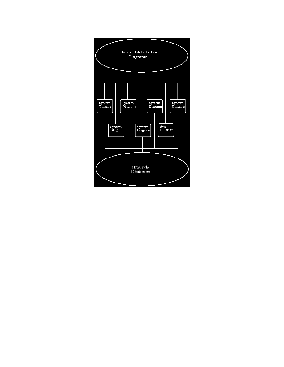
Diagrams are presented in three main categories:
^
Power Distribution Diagrams
^
System Diagrams
^
Grounds Diagrams
Types of Diagrams Shown
Block Diagrams can be found at the beginning of some sets of diagrams. These block diagrams provide an overview of the systems that are
detailed on the detailed diagrams that follow them. Block diagrams are not suitable for diagnostic operations.
Detailed Diagrams (usually provided in sets of more than one diagram) provide detailed system information suitable for diagnostic operations.
Related Diagrams that are not an intergal part of the detailed diagrams, but may have a relationship to them, are also included.
All components connected to the control module are shown in order to provide easy understanding of the system component interactions.
Unless otherwise identified, diagrams shown in a set will be of the Detailed Diagrams type.
NOTE: All wiring connections between components are shown exactly as they exist in the vehicles. It is important to realize, however, that no attempt
has been made on the diagram to represent components and wiring as they physically appear on the vehicle. For example, a 4-foot length of wire is
treated no differently in a diagram from one which is only a few inches long. Furthermore, to aid in understanding electrical (electronic) operation,
wiring inside complicated components has been simplified.
Complete Circuit Operation
Each circuit is shown completely and independently in one set of diagrams. Other components which are connected to the circuit may not be shown
unless they influence the circuit operation.