
Focus ZX5 L4-2.0L DOHC VIN 3 (2002)
Current Flow (1)
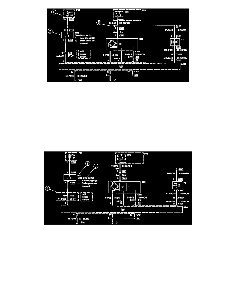
Each set of diagrams normally starts with the component that powers the circuit such as a fuse or the ignition switch. Current flow is shown from the
power source at the top of the diagram to ground at the bottom of the diagram. In order to concentrate on the essential parts, power supply and ground
connections are sometimes simplified by a dashed line in the diagrams.
Switch Positions (2)
Within the diagram, all switches, sensors and relays are shown "at rest" (as if the Ignition Switch were OFF).
Splices (3)
An arrow indicates that the splice is not shown completely. If the splice is not shown completely in the diagram but is complete within the set of
diagrams, the number of the diagram where the splice is completed is indicated next to the arrow.
Boxes (4)
A thin dashed box on a diagram indicates a pan of the circuit which is only present for a particular vehicle model, country, or option. These qualifiers are
shown next to the box on the diagram.
Component Names and Notes (5)
Component names are placed on the right hand side of each component. Any notes that describe switch positions or operating conditions follow the
name. Descriptions of the internals of the component are also included here.
Component Identification Numbers (6)
Each component on each diagram has a component identification number located to the upper right hand side of the component. By finding this number
or the component name in one of the the A-Z Component Lists, the Component Location description for that component can easily be found. See:
Locations/Component Locations/A-Z Component List