| Diagnosis and Testing Refer to Wiring Diagrams Section 419-08, for schematic and connector information. Inspection and Verification - Verify the customers concern.
- Visually inspect for obvious signs of electrical damage.
Visual Inspection Chart | Electrical | | Fuse(s) | | Wiring Harness | | Electrical connector(s) | | Microphone | | Cellular phone antenna | | Cellular phone speaker | | Handset holder | | Cellular phone | | Portable Support Electronics (PSE) Module | - Verify that the cellular phone operates correctly out of the vehicle before proceeding to the next step.
- Verify the audio unit or navigation system display module is working correctly before proceeding to the next step.
- If an obvious cause for an observed or reported concern is found, correct the cause (if possible) before proceeding to the next step.
- If the cause is not visually evident, verify the symptom and refer to the Symptom Chart.
Symptom Chart | Symptom | Possible Sources | Action | | The handset battery does not charge | * Circuit(s). * Handset holder. * Cellular phone. * PSE Module. | * | | Interference from the cellular phone speaker - vehicles with Traffic Pro navigation system | * Incorrect settings of the navigation system display module. | * MAKE sure that MUTE is selected in the navigation system display module RADIO MODE. TEST the system for normal operation. | | Reduced sound or no sound through the speaker | * Circuit(s). * Cellular phone speaker. * Handset holder. * PSE Module. | * | | No SVC display stays on | * Cellular phone antenna. * Handset holder. | * | | The hands-free system is inoperative - vehicles built up to 10/2005 | * Cellular phone and handset holder electrical contacts. | * CHECK the cellular phone is correctly installed into the handset holder. TEST the system for normal operation. | | The hands-free system is inoperative - vehicles built 10/2005 onwards | * Circuit(s). * Microphone. * PSE Module. | * | | * MS CAN bus. | * REFER to WDS. | | Microphone sensitivity too low (user is difficult to hear when making calls) | * Microphone incorrectly adjusted. | * INCREASE the microphone sensitivity on the PSE module during a conversation. | | * Microphone location incorrect. | * CHECK the location of the microphone. INSTALL the microphone in the correct location if necessary. | | Microphone sensitivity too high (user hears their own voice when making calls) | * Microphone incorrectly adjusted. | * DECREASE the microphone sensitivity on the PSE module during a conversation. | | Whistling noise when the cellular phone is in use | * Microphone incorrectly adjusted. | * DECREASE the microphone sensitivity on the PSE module during a conversation. | | The cellular phone speaker operates but the audio unit speakers do not mute. | * PSE module wiring harness. * Electrical connection to the audio unit or navigation system display module. * Threshold voltage to the audio unit or navigation system display module is not achieved. | * INSTALL a new PSE module wiring harness. TEST the system for normal operation. If the concern persists, INSTALL a new PSE module. TEST the system for normal operation. | | * Audio unit or navigation system display module. | * INSTALL a new audio unit.
REFER to: Audio Unit - Vehicles Built Up To: 10/2005 (415-01 Audio Unit, Removal and Installation) /
Audio Unit - Vehicles Built From: 10/2005 (415-01 Audio Unit, Removal and Installation).
* INSTALL a new navigation system display module. Vehicles with Travel Pilot,
REFER to: Navigation System Display Module (419-07A Navigation System - Vehicles With: Travel Pilot, Removal and Installation).
Vehicles with Traffic Pro,
REFER to: Navigation System Display Module (419-07B Navigation System - Vehicles With: Traffic Pro, Removal and Installation).
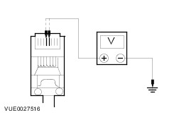
| Pinpoint Test | PINPOINT TEST A : THE HANDSET BATTERY DOES NOT POWER UP | | TEST CONDITIONS | DETAILS/RESULTS/ACTIONS | | A1: CHECK THE POWER SUPPLY TO THE PSE MODULE | | | 1 Disconnect PSE Module C1026. | | | 2 Ignition switch in position I. | | | 3 Measure the voltage between the PSE module C1026 pin 4, (PK), harness side and ground; and the PSE module C1026 pin 5, (GY), harness side and ground. | | | Is the voltage greater than 10 volts? Yes No | | A2: CHECK THE PSE MODULE POWER WIRING HARNESS FOR OPEN CIRCUIT | | | 1 Disconnect PSE Harness C1025. | | | 2 Measure the resistance between the PSE module C1026 pin 4, (PK), harness side and PSE harness C1025 pin 1, (YE), harness side; and the PSE module C1026 pin 5, (GY), harness side and PSE harness C1025 pin 1, (YE), harness side. | | | Is the resistances less than 5 ohms? Yes For navigation display module, GO to A6. No REPAIR the circuit. TEST the system for normal operation. | | A3: CHECK THE PSE MODULE FOR GROUND | | | 1 Connect PSE Harness C1025. | | | 2 Ignition switch in position 0. | | | 3 Measure the resistance between the PSE module C1026 pin 3, (BN), harness side and ground; and the PSE module C1026 pin 6, (YE), harness side and ground. | | | Is the resistance less than 5 ohms? Yes CLEAN the handset holder and cellular phone electrical connectors. TEST the system for normal operation. If the concern persists, INSTALL a new handset holder. TEST the system for normal operation. If the concern persists, INSTALL a new PSE module. No | | A4: CHECK THE PSE MODULE GROUND WIRING HARNESS FOR OPEN CIRCUIT | | | 1 Disconnect PSE Harness C1025. | | | 2 Measure the resistance between the PSE module C1026 pin 3, (BN), harness side and PSE harness C1025 pin 3, (YE), harness side; and the PSE module C1026 pin 6, (YE), harness side and PSE harness C1025 pin 3, (YE), harness side. | | | Is the resistances less than 5 ohms? Yes For navigation display module, GO to A8. No INSTALL a new PSE module wiring harness. TEST the system for normal operation. | | A5: CHECK THE PSE MODULE POWER WIRING HARNESS TO AUDIO UNIT WIRING HARNESS FOR OPEN CIRCUIT | | | 1 Disconnect Audio Unit C344. | | | 2 Measure the resistance between the PSE module C1025 pin 1, (YE), harness side and audio unit C344 pin 2, circuit 75-MD15 (YE/GN), harness side. | | | Is the resistances less than 5 ohms? Yes For additional information.
REFER to: Audio System - Vehicles Built Up To: 10/2005 (415-00 Information and Entertainment System - General Information, Diagnosis and Testing) /
Audio System - Vehicles Built From: 10/2005 (415-00 Information and Entertainment System - General Information, Diagnosis and Testing).
No REPAIR the circuit. TEST the system for normal operation. | | A6: CHECK THE PSE MODULE POWER WIRING HARNESS TO NAVIGATION SYSTEM DISPLAY MODULE WIRING HARNESS FOR OPEN CIRCUIT | | | 1 Disconnect Navigation System Display Module C717. | | | 2 Measure the resistance between the PSE module C1025 pin 1, (YE), harness side and navigation system display module C717 pin 7, circuit 75-MD15 (YE/GN), harness side. | | | Is the resistances less than 5 ohms? Yes For additional information, for vehicles with Travel Pilot
REFER to: Navigation System (419-07A Navigation System - Vehicles With: Travel Pilot, Diagnosis and Testing).
for vehicles with Traffic Pro,
REFER to: Navigation System (419-07B Navigation System - Vehicles With: Traffic Pro, Diagnosis and Testing).
No REPAIR the circuit. TEST the system for normal operation. | | A7: CHECK THE PSE MODULE GROUND WIRING HARNESS TO AUDIO UNIT WIRING HARNESS FOR OPEN CIRCUIT | | | 1 Disconnect Audio Unit C344. | | | 2 Measure the resistance between the PSE module C1025 pin 3, (BN), harness side and audio unit C344 pin 13, circuit 91-MD15 (BK/GN), harness side. | | | Is the resistances less than 5 ohms? Yes For additional information,
REFER to: Audio System - Vehicles Built Up To: 10/2005 (415-00 Information and Entertainment System - General Information, Diagnosis and Testing) /
Audio System - Vehicles Built From: 10/2005 (415-00 Information and Entertainment System - General Information, Diagnosis and Testing).
No REPAIR the circuit. TEST the system for normal operation. | | A8: CHECK THE PSE MODULE GROUND WIRING HARNESS TO NAVIGATION SYSTEM DISPLAY MODULE WIRING HARNESS FOR OPEN CIRCUIT | | | 1 Disconnect Navigation System Display Module C717. | | | 2 Measure the resistance between the PSE module C1025 pin 3, (BN), harness side and navigation system display module C717 pin 8, circuit 91-MD15 (BK/GN), harness side. | | | Is the resistances less than 5 ohms? Yes For additional information, for vehicles with Travel Pilot
REFER to: Navigation System (419-07A Navigation System - Vehicles With: Travel Pilot, Diagnosis and Testing).
for vehicles with Traffic Pro,
REFER to: Navigation System (419-07B Navigation System - Vehicles With: Traffic Pro, Diagnosis and Testing).
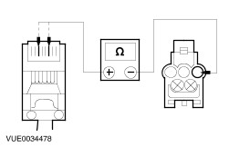
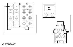
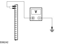
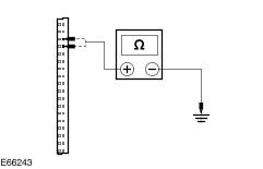
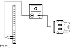
No REPAIR the circuit. TEST the system for normal operation. | | PINPOINT TEST B : REDUCED SOUND OR NO SOUND THROUGH THE SPEAKER | | TEST CONDITIONS | DETAILS/RESULTS/ACTIONS | | B1: CHECK THE CELLULAR PHONE SPEAKER | | | 1 Disconnect Cellular Phone Speaker. | | | 2 Measure the resistance between the speaker terminals (component side). | | | Is the resistance between 3 and 5 ohms? Yes REPAIR if necessary the circuit between the cellular phone speaker and the PSE module. TEST the system for normal operation. If the concern persists, CLEAN the handset holder and cellular phone electrical connectors. TEST the system for normal operation. INSTALL a new handset holder. TEST the system for normal operation. If the concern persists, INSTALL a new PSE module. TEST the system for normal operation. No INSTALL a new cellular phone speaker. TEST the system for normal operation. | | PINPOINT TEST C : NO SVC DISPLAY STAYS ON | | TEST CONDITIONS | DETAILS/RESULTS/ACTIONS | | C1: CHECK THE HANDSET HOLDER ANTENNA CABLE FOR OPEN CIRCUIT | | | 1 Disconnect Handset Holder Antenna Cable. | | | 2 Measure the resistance between the center pin of the cellular phone handset holder antenna connection and the center pin of the antenna cable connector. | | | Is the resistance less than 1 ohm? Yes TEST the system for normal operation. No INSTALL a new handset holder. TEST the system for normal operation. | | PINPOINT TEST D : THE HANDS-FREE SYSTEM IS INOPERATIVE - VEHICLES BUILT 10/2005 ONWARDS | | TEST CONDITIONS | DETAILS/RESULTS/ACTIONS | | D1: CHECK THE PSE MODULE CIRCUIT FOR POWER | | | 1 Disconnect PSE Module C796. | | | 2 Measure the voltage between the PSE module C796 pin 17, circuit 29-MC12A (OG/YE) and between the PSE module C796 pin 18, circuit 29-MC12 (OG/YE), harness side and ground. | | | Are the voltages greater than 10 volts? Yes No REPAIR circuit 29-MC12A (OG/YE) or circuit 29-MC12 (OG/YE). TEST the system for normal operation. | | D2: CHECK THE PSE MODULE CIRCUIT FOR GROUND | | | 1 Measure the resistance between the PSE module C796 pin 33, circuit 91-MC12A (BK/YE), harness side and ground, and between the PSE module C796 pin 34, circuit 91-MC12 (BK/YE), harness side and ground. | | | Are the resistances less than 5 ohms? Yes No REPAIR circuit 91-MC12A (BK/YE) or circuit 91-MC12 (BK/YE). TEST the system for normal operation. | | D3: CHECK CIRCUIT 8-MC12 (WH) AND CIRCUIT 9-MC12 (BN) FOR OPEN CIRCUIT | | | 1 Disconnect Audio Unit C777. | | | 2 Measure the resistances between: - the PSE module C796 pin 1, circuit 8-MC12 (WH), harness side and the audio unit C777 pin 1, circuit 8-MC12 (WH), harness side.
- the PSE module C796 pin 2, circuit 9-MC12 (BN), harness side and the audio unit C777 pin 7, circuit 9-MC12 (BN), harness side.
| | | Are the resistances less than 5 ohms? Yes No REPAIR circuit 8-MC12 (WH) or circuit 9-MC12 (BN). TEST the system for normal operation. | | D4: CHECK THE MICROPHONE CIRCUITS FOR OPEN CIRCUIT | | | 1 Disconnect Microphone C798. | | | 2 Measure the resistances between: - the PSE module C796 pin 3, circuit 8-MC8 (WH/RD), harness side and the microphone C798 pin 1, circuit 8-MC8 (WH/RD), harness side.
- the PSE module C796 pin 4, circuit 48-MC8A (BK), harness side and the microphone C798 pin 2, circuit 48-MC8B (BK), harness side.
| | | Are the resistances less than 5 ohms? Yes INSTALL a new microphone. TEST the system for normal operation. If the concern persists, INSTALL a new PSE module. TEST the system for normal operation. No REPAIR circuit 8-MC8 (WH/RD) or circuit 48-MC8A (BK). TEST the system for normal operation. | |