
Seats
- Make
- Ford
- Model
- Fusion Factory Service Manual
- Year
- 2007
- Section
- 501-10 Seating › Diagnosis and testing › Seats
Seats
 |
Fluke 73III Automotive Meter
105-R0057 or equivalent |
 |
Vehicle Communication Module (VCM) and Integrated Diagnostic System (IDS)
software with appropriate hardware, or equivalent scan tool |
 |
Diagnostic Tool, Restraint System
418-133 (014-R1076) (2 required) |
Restraint System Diagnostic Tool Warning
WARNING: These tools are for restraint system service only. Remove from vehicle prior to road use. Failure to remove could result in injury and possible violation of vehicle safety standards.
Medium Speed Controller Area Network (MS-CAN)
This vehicle utilizes a communication system called a medium-speed controller area network (MS-CAN). When diagnosing the memory seat or climate controlled seat, use a Vehicle Communication Module (VCM) and Integrated Diagnostic System (IDS) software with appropriate hardware, or equivalent scan tool with the latest software update with the capability of communicating over the MS-CAN bus.
Principles of Operation
Driver and Passenger Power Seats Without Memory
The 10-way seat control feature (MKZ passenger seat only) moves the seat in 10 possible directions: the seat can be moved forward or backward and the front and back of the cushion can be moved up and down independently. The backrest of the seat can be moved forward and backward, and the lumbar can be moved IN and OUT. All 10 positions are controlled by one switch. The power seat feature operates independent of the ignition switch position.
The 6-way power seat feature moves the seat in 6 possible directions: the seat can be moved forward or backward and the front and back of the cushion can be moved up and down independently. The power seat feature operates independent of the ignition switch position.
The power seat motors are hardwired to the seat control switch. The circuits are normally at ground through the seat control switch. An individual circuit is switched to power when a specific adjustment position is selected.
Power Driver Seat With Memory
The memory driver seat feature allows the driver to program a personalized seat position that can be recalled using the memory switch or a remote keyless entry (RKE) transmitter. There are 2 memory settings possible. The outside rear view mirror positions and the power adjustable pedals (if equipped) are also stored and recalled with the power driver seat positions.
The driver power seat is controlled by the driver seat module (DSM), if equipped. A new DSM must be configured after installation. Refer to Section 418-01.
The driver seat control switch provides voltage to the DSM when activated. The NEUTRAL position of each driver seat control switch position is a ground state through the seat control switch contacts. A voltage input causes the DSM to power the appropriate motor until the input is removed. Ground is the normal state of the motor circuits through the DSM and is not switched to control the motors. The DSM internally switches the appropriate circuit from ground to power for operating the motors.
As the seat is adjusted, the DSM constantly monitors the motor position sensors to record the current seat position. The DSM will remove power from the motor upon termination of the seat control switch input or if the DSM does not see movement from the motor by monitoring the position sensor. The DSM must be calibrated to the driver seat track for correct memory seat operation. Refer to Seat Calibration in this section. Once the DSM is calibrated to the seat track, it will only allow movement within the calibrated range.
The DSM communicates diagnostic trouble code (DTC) and other information using the MS-CAN communication bus. It should be noted for diagnostics that because CAN bus communication is more robust and reliable than other methods, it may be possible to have limited module communication with one of the CAN bus circuits disconnected or shorted to ground. Refer to Section 418-00 for additional information concerning MS-CAN bus communication.
Programming Memory Seat Positions
- A power driver seat position can be stored at any time. The driver must move the seat to the desired position using the driver seat control switch. The driver must then depress the memory SET switch which activates the memory SET switch light emitting diode (LED). Within 5 seconds (before the LED goes out), the driver must select a memory position. Memory 1 is selected by depressing memory switch 1. Memory 2 is selected by depressing memory switch 2.
- If no memory switch input is received within the 5-second time limit, the operation is aborted and the memory SET switch LED is turned OFF. If one of the following inputs is received during the 5-second programming limit, the operation is
aborted and the memory SET switch LED is turned OFF:
- Power driver seat control switch
- Memory SET switch
- Power adjustable pedal switch
Recalling a Stored Memory Seat Position
NOTE: A memory recall can be initiated only if the vehicle is in PARK or NEUTRAL gear and the ignition switch is not in START. A memory recall in progress will not be affected by moving the ignition switch to START or by moving the gearshift lever out of PARK or NEUTRAL.
Once the driver has stored the driver seat position, the driver can recall the setting by depressing the corresponding memory switch or by using a programmed remote entry transmitter.
The driver can recall the desired driver seat position by depressing one of the memory recall switches. Depressing memory switch 1 will initiate a recall of the power driver seat position stored in Memory 1. Depressing memory switch 2 will initiate a recall of the power driver seat position stored in Memory 2.
A remote entry transmitter can be used to recall previously set memory positions. The transmitter that has been assigned with personality 1 is capable of recalling memory position 1 only. Similarly, the personality 2 transmitter can recall only memory position 2.
Memory recall occurs when the unlock switch is depressed on the remote entry transmitter. The second depression of the unlock switch, which unlocks passenger doors, does not initiate a memory recall.
A memory recall in progress does not prohibit the initiation of another memory recall; the most recently requested memory recall will be executed.
Memory positions that have not been programmed will not initiate any motion for the power driver seat, power memory rear view mirrors or adjustable pedals.
Easy Exit/Easy Entry
The easy exit function moves the seat backwards about 2 inches when the ignition key is removed from the ignition switch. The DSM receives a key out command over the MS-CAN communication network and powers the driver seat rearward. This function will not operate if the seat is less than the travel distance to the end of the track or the function has been deactivated. The DSM will also cancel this operation if a valid input command is received, such as the seat control switch or memory recall request.
The DSM will record the current seat position before powering the seat for an easy exit function. This recorded position will be used to return the seat to this position on the easy entry operation. During easy entry operation, the seat is returned to the position previous to the easy exit operation. Easy entry operation will be cancelled if a valid input command is received by the DSM.
The easy exit/easy entry feature can be activated or deactivated using a scan tool or via the message center. Refer to Section 418-01 or the owner's literature.
Heated Seats
Vehicles equipped with front heated seats are equipped with a single-heated seat module to control both front heated seats. The heated seat module is located on the passenger seat track. The electronic automatic temperature control (EATC) module includes both driver and passenger heated seat control buttons and indicators. The heated seat system will function independently of the vehicle's climate control system. A momentary ground signal is transmitted to the heated seat module when a heated seat switch button on the EATC module is depressed and ignition switched voltage is supplied. Upon receiving each control signal to an input circuit, the heated seat module will decrease one setting (the sequence is HI, LOW, OFF, HI, etc.). When a heated seat is set to HI, both LED indicators above that heated seat's control button will illuminate. When a heated seat is set to LOW, only one LED indicator above that switch will illuminate. When activated, the heated seat module supplies power to the selected seat's heater circuit. Each seat's cushion heater mat and backrest heater mat is connector in a series circuit to the heated seat module and powered by the output circuit for that seat and ground. The heated seat module monitors inputs from a temperature sensor, located in each seat's cushion heater mat and maintains seat temperature by regulating current flow to the heater circuits. The heated seat module will remain ON until the heated seat switch button is depressed to cycle the heated seat module OFF or a 15-minute time-out period occurs. If ignition power is switched OFF, the heated seat module will enter an OFF state.
Climate Controlled Seat System
NOTE: When installing a new dual climate control seat module (DCSM), it is necessary to carry out programmable module installation (PMI). Refer to Section 418-01.
Both the driver and front passenger climate controlled seats are independently controlled electronically by the DCSM mounted to the bottom of the passenger seat cushion. The climate controlled seat system only operates with the engine running, however, if using a scan tool to command the DCSM, diagnostic testing can be carried out with the ignition switch key ON engine OFF (KOEO). The system receives power from battery junction box (BJB) fuse 12 (30A) feeding battery voltage on circuit SBB12 (GN/RD) into DCSM C3305a pin F. The system also receives power from BJB fuse 11 (30A) feeding battery voltage on circuit SBB11 (BU/RD) into DCSM C3305a pin E.
If only one of the BJB fuses 11 or 12 open, both seats will remain operational because the power feed circuits are internally connected in the DCSM.
Both climate controlled seats operate independently. If a fault occurs setting a DTC specific to either climate controlled seat, only the affected seat will be disabled by the module and the other will remain operational.
The 4 switches (identified with seat icons) on the dual-zone electronic automatic temperature control (EATC) module activate each seat system setting and illuminate LEDs above each switch to indicate the operating mode, 3 LEDs for HIGH, 2 LEDs for MED or 1 LED for LOW. The push-buttons with the blue seat icon operate the seat cooling mode and the push-buttons with the red seat icon operate the seat heating mode. The climate controlled seat system is not equipped with auto-mode.
Each driver and front passenger seat cushion is equipped with a thermo-electric device (TED) assembly that includes a seat blower (fan motor, serviced as an assembly with the TED). Similarly, each driver and front passenger seat backrest is also equipped with its own TED assembly with blower. Cabin air is drawn through the blower and distributed to each of the TED modules located in the seat cushion and backrest. The TEDs then heat or cool the air. The air is then directed into the foam pad and manifold where it is distributed along the surface of the cushion and backrest of the seat. Once the system is activated, the DCSM uses a set of flexible algorithms to control the heating/cooling modes and the blower speed dependant on the EATC seat switch settings.
The TED uses a ''Peltier'' circuit of P-type and N-type semiconductors connected in series using copper electrical conductors. The semiconductors are sandwiched between 2 copper heat exchangers. When current is applied to the TED, one side releases energy as heat, while the opposite side absorbs energy and gets cold. By reversing the current flow, the hot and cold sides reverse.
NOTE: Avoid applying power directly to a TED for testing its operation. Doing so may cause damage to the TED or shorten its usable life.
The temperature differences between the individual heated and cooled settings is minimal. For example, it is difficult to distinguish between LOW COOL and MEDIUM COOL settings. Measuring seat temperature at different settings is possible by monitoring the DCSM PIDs using the scan tool.
The EATC module communicates climate controlled seat commands to the DCSM using the medium speed controller area network (MS-CAN) communication bus. The MS-CAN bus is connected to the data link connector (DLC) for diagnostic use. No direct connection exists between the DCSM and EATC for the climate controlled seat switches. The climate controlled seats can be commanded using the diagnostic tool to verify both module communication on the MS-CAN bus and operation of the DCSM. This method may be useful for isolating a control switch concern. It should also be noted that because CAN bus communication is more robust and reliable than other methods, it may be possible to have limited module communication with one of the CAN bus circuits disconnected or shorted to ground. Refer to Section 418-00 for additional information concerning CAN bus communication.
Heating Characteristics
NOTE: The presence of overtemperature faults (DTCs B2729, B2730, B272A and B272B) can be induced by incorrect operation of the climate controlled seat system after an initial HEAT setting has been attained. If a HEAT setting is repeatedly turned OFF and ON in an attempt to increase the seat temperature, an overtemperature condition can result and the DTC(s) will be set.
- In HEAT mode, the TED circuits of a given seat are wired in parallel internally in the DCSM.
- The climate controlled seat system draws approximately 24 amperes, with both seats heating, until reaching the set point and then the system operates at a reduced amperage to maintain the climate setting.
- In HEAT mode, the TED can add up to 40°C-60°C (72°F-108°F) to the ambient air temperature entering the system.
- There are 3 manual settings based on the LEDs above each seat heat switch button on the EATC. The first setting is HIGH (3 LEDs), the second setting is MED (2 LEDs), the third is LOW (1 LED) then OFF (no LEDs).
- In the LOW setting, the climate controlled seat module is set to maintain TED temperature at approximately 46°C (115°F).
- In the HIGH setting, the climate controlled seat module is set to maintain TED temperature at 65°C (149°F).
- If the temperature at one of the TEDs rises above 110°C (230°F) in the HEAT mode or 65°C (149°F) in the COOL mode for more than 4 seconds, the DCSM will record an overtemperature DTC, remove power from the TEDs and go into blower only mode in an attempt to cool down the TEDs. If the TEDs temperature has not dropped to 105°C (221°F) in the HEAT mode or 60°C (140°F) in the cool mode after 30 seconds, the DCSM will shut down and remain off until the ignition is cycled. Also if the DCSM detects an overtemperature twice during the same ignition cycle, it will also shut down.
- When heating, the DCSM will vary the speed of the fans and the TED duty cycle in order to reach and maintain the temperature determined by the switch setting.
- Seat heating has a maximum operating duration of 15 minutes.
| Climate Controlled Seat Heat State | Initial Temperature | Final Temperature |
|---|---|---|
| HIGH | 90°C (194°F) | 65°C (149°F) |
| MED | 80°C (176°F) | 60°C (140°F) |
| LOW | 75°C (167°F) | 46°C (115°F) |
Cooling Characteristics
- In cool mode, the TED circuits of a given seat are wired in series internally in the DCSM.
- The climate controlled seat system draws approximately 10 amps for the first 12 minutes and will operate at 2 amps thereafter.
- In cool mode, the TED can remove up to 8°C (14°F) from the ambient air temperature entering the system.
- There are 3 manual settings based on the LEDs above each seat cool switch button on the EATC. The first setting is HIGH (3 LEDs), the second setting is MED (2 LEDs) and the third is LOW (1 LED) then OFF (no LEDs).
- If the temperature at one of the TEDs falls below 5°C (41°F), the climate controlled seat module will shut down the TEDs. If the temperature continues to drop below 2°C (36°F), the climate controlled seat module will shut down the blower motors.
- When cooling, the DCSM maintains constant speed of the fans and constant TED supply voltage (duty cycle) in open loop cool mode.
- Seat cooling has a maximum operating duration of 30 minutes.
| Climate Controlled Seat Cool State | TED Voltage | TED Supply Duty Cycle |
|---|---|---|
| HIGH | Vbat | 100% |
| MED | Vbat | 75% |
| LOW | Vbat | 50% |
The climate controlled seat system is deactivated by one of the following actions:
- Selecting the EATC module setting to manual OFF.
- Turning the vehicle OFF.
Inspection and Verification
- Verify the customer concern.
- Visually inspect for obvious signs of mechanical and electrical damage.
| Mechanical | Electrical |
|---|---|
|
|
- If an obvious cause for an observed or reported concern is found, correct the cause (if possible) before proceeding to the next step.
- If the concern is with the power seat (non-memory seat) or heated seat and the cause is not visually evident, verify the symptom and GO to Symptom Chart.
-
NOTE: Make sure to use the latest scan tool software release.
If the concern is with the memory seat or climate controlled seat and the cause is not visually evident, connect the scan tool to the data link connector (DLC). -
NOTE: The vehicle communication module (VCM) LED prove out confirms power and ground from the DLC are provided to the VCM.
If the scan tool does not communicate with the VCM:- check the VCM connection to the vehicle.
- check the scan tool connection to the VCM.
- refer to Section 418-00, No power to the scan tool, to diagnose no communication with the scan tool.
- If the scan tool does not communicate with the vehicle:
- verify the ignition key is in the ON position.
- verify the scan tool operation with a known good vehicle.
- refer to Section 418-00 to diagnose no response from the powertrain control module (PCM).
- Carry out the network test.
- If the scan tool responds with no communication for one or more modules, refer to Section 418-00.
- If the network test passes, retrieve and record continuous memory diagnostic trouble codes (DTCs).
- Clear the continuous DTCs and carry out the self-test diagnostics for the DSM, DDM, DCSM.
- If the DTCs retrieved are related to the concern, go to DSM Diagnostic Trouble Code (DTC) Index, DCSM DTC Index or DDM DTC Index. For all other DTCs, refer to Section 419-10.
- If no DTCs related to the concern are retrieved, GO to Symptom Chart.
Driver Seat Module (DSM) Diagnostic Trouble Code (DTC) Index
| DTC | Description | Retrieved | Action |
|---|---|---|---|
| B1317 | Battery Voltage High | Continuous | REFER to Section 414-00. |
| B1318 | Battery Voltage Low | Continuous | REFER to Section 414-00. |
| B1342 | ECU Is Faulted | On-Demand and Continuous | INSTALL a new DSM. REFER to Section 419-10. CARRY OUT programmable module installation (PMI). REFER to Section 418-01. |
| B1663 | Seat Driver Front Up/Down Motor Stalled | On-Demand | If the motor does not operate, Go To Pinpoint Test J. If motor operates, Go To Pinpoint Test K. |
| B1664 | Seat Driver Rear Up/Down Motor Stalled | On-Demand | If the motor does not operate, Go To Pinpoint Test J. If motor operates, Go To Pinpoint Test K. |
| B1665 | Seat Driver Forward/Backward Motor Stalled | On-Demand | If the motor does not operate, Go To Pinpoint Test J. If motor operates, Go To Pinpoint Test K. |
| B1666 | Seat Driver Recline Motor Stalled | On-Demand | If the motor does not operate, Go To Pinpoint Test J. If motor operates, Go To Pinpoint Test K. |
| B1667 | Mirror Driver Up/Down Motor Stalled | On-Demand | REFER to Section 501-09. |
| B1668 | Mirror Driver Right/Left Motor Stalled | On-Demand | REFER to Section 501-09. |
| B1669 | Mirror Passenger Up/Down Motor Stalled | On-Demand | REFER to Section 501-09. |
| B1670 | Mirror Passenger Right/Left Motor Stalled | On-Demand | REFER to Section 501-09. |
| B1703 | Seat Driver Recline Forward Switch Circuit Short to Battery | On-Demand and Continuous | Go To Pinpoint Test J. |
| B1707 | Seat Driver Recline Rearward Switch Circuit Short to Battery | On-Demand and Continuous | Go To Pinpoint Test J. |
| B1711 | Seat Driver Front Up Switch Circuit Short to Battery | On-Demand and Continuous | Go To Pinpoint Test J. |
| B1715 | Seat Driver Front Down Switch Circuit Short to Battery | On-Demand and Continuous | Go To Pinpoint Test J. |
| B1719 | Seat Driver Forward Switch Circuit Short to Battery | On-Demand and Continuous | Go To Pinpoint Test J. |
| B1723 | Seat Driver Rearward Switch Circuit Short to Battery | On-Demand and Continuous | Go To Pinpoint Test J. |
| B1727 | Seat Driver Rear Up Switch Circuit Short to Battery | On-Demand and Continuous | Go To Pinpoint Test J. |
| B1731 | Seat Driver Rear Down Switch Circuit Short to Battery | On-Demand and Continuous | Go To Pinpoint Test J. |
| B1952 | Seat Rear Up/Down Position Feedback Circuit Short to Battery | On-Demand and Continuous | Go To Pinpoint Test K. |
| B1953 | Seat Rear Up/Down Position Feedback Circuit Short to Ground | On-Demand and Continuous | Go To Pinpoint Test K. |
| B1956 | Seat Front Up/Down Position Feedback Circuit Short to Battery | On-Demand and Continuous | Go To Pinpoint Test K. |
| B1957 | Seat Front Up/Down Position Feedback Circuit Short to Ground | On-Demand and Continuous | Go To Pinpoint Test K. |
| B1960 | Seat Recline Forward/Backward Position Feedback Circuit Short to Battery | On-Demand and Continuous | Go To Pinpoint Test K. |
| B1961 | Seat Recline Forward/Backward Position Feedback Circuit Short to Ground | On-Demand and Continuous | Go To Pinpoint Test K. |
| B1964 | Seat Horizontal Forward/Rearward Position Feedback Circuit Short to Battery | On-Demand and Continuous | Go To Pinpoint Test K. |
| B1965 | Seat Horizontal Forward/Rearward Position Feedback Circuit Short to Ground | On-Demand and Continuous | Go To Pinpoint Test K. |
| B2143 | Non Volatile Memory Failure (EEPROM) | Continuous | CALIBRATE the DSM. REFER to Section 418-01. CLEAR the DTCs. REPEAT the self-test. If the DTC resets, INSTALL a new DSM and CARRY OUT programmable module installation (PMI). REFER to Section 419-10. |
| B2223 | Mirror Driver Drive Circuit Failure | On-Demand and Continuous | REFER to Section 501-09. |
| B2224 | Mirror Passenger Drive Circuit Failure | On-Demand and Continuous | REFER to Section 501-09. |
| B2312 | Mirror Passenger Horizontal Feedback Potentiometer Circuit Failure | On-Demand and Continuous | REFER to Section 501-09. |
| B2314 | Mirror Passenger Horizontal Feedback Potentiometer Circuit Short to Battery | On-Demand and Continuous | REFER to Section 501-09. |
| B2316 | Mirror Passenger Vertical Feedback Potentiometer Circuit Failure | On-Demand and Continuous | REFER to Section 501-09. |
| B2318 | Mirror Passenger Vertical Feedback Potentiometer Circuit Short to Battery | On-Demand and Continuous | REFER to Section 501-09. |
| B2477 | Module Configuration Failure | Continuous | CARRY OUT programmable module installation (PMI) on the DSM. CLEAR the DTC. If the DTC does not clear, CARRY OUT PMI on the DSM once again. CLEAR the DTC. If the DTC does not CLEAR, INSTALL a new DSM and CARRY OUT PMI on the new DSM. REFER to Section 419-10. CLEAR the DTC. CARRY OUT the self-test. |
| U1900 | CAN Communication Bus Fault — Receive Error | On-Demand and Continuous |
NOTE: Do not install a new DSM as part of repair for a DSM DTC U1900 fault. The DSM is not the source of the fault when DTC U1900 is present. If DTC U1900 is present on-demand, CHECK the instrument cluster module for DTCs and REPAIR as needed. REFER to Section 413-01.If DTC U1900 is present continuous only, CHECK for an intermittent MS-CAN fault. REFER to Section 418-00 to diagnose the MS-CAN network concern. |
| U2050 | No Application Code Present | On-Demand and Continuous | CALIBRATE the DSM. REFER to Section 418-01. CLEAR the DTC. REPEAT the self-test. If the DTC does not clear or is retrieved again, INSTALL a new DSM and CARRY OUT programmable module installation (PMI). REFER to Section 419-10. |
Driver Door Module (DDM) Diagnostic Trouble Code (DTC) Index
NOTE: Only the memory set switch DTCs are listed. For all DDM DTCs, refer to Section 419-10.
| DTC | Description | Retrieved | Action |
|---|---|---|---|
| B1530 | Memory Set Switch Circuit Short to Ground | On-Demand and Continuous | REFER to Section 501-09. |
| B1534 | Memory 1 Switch Circuit Short to Ground | On-Demand and Continuous | REFER to Section 501-09. |
| B1538 | Memory 2 Switch Circuit Short to Ground | On-Demand and Continuous | REFER to Section 501-09. |
| B2084 | Memory SET Indicator Short to Ground | On-Demand and Continuous | REFER to Section 501-09. |
Dual Climate Controlled Seat Module (DCSM) Diagnostic Trouble Code (DTC) Index
| DTC | Description | Retrieved | Action |
|---|---|---|---|
| B103B | Thermoelectric Driver Overcurrent Low | On-Demand and Continuous | Go To Pinpoint Test S. |
| B103C | Thermoelectric Driver Open Load | On-Demand and Continuous | Go To Pinpoint Test T. |
| B103D | Blower Driver Overtemperature | On-Demand and Continuous | Go To Pinpoint Test U. |
| B1111 | Driver Thermoelectric Device Control Overtemperature Fault | On-Demand and Continuous | Go To Pinpoint Test S. |
| B1113 | Passenger Thermoelectric Device Control Overtemperature Fault | On-Demand and Continuous | Go To Pinpoint Test V. |
| B111B | Passenger Thermoelectric Driver Overcurrent Low | On-Demand and Continuous | Go To Pinpoint Test V. |
| B111C | Passenger Thermoelectric Driver Open Load | On-Demand and Continuous | Go To Pinpoint Test W. |
| B111D | Passenger Blower Driver Overtemperature | On-Demand and Continuous | Go To Pinpoint Test X. |
| B1342 | ECU is Faulted | On-Demand and Continuous | CLEAR the DTC. CARRY OUT the self-test. If the DTC does not clear or is retrieved again, INSTALL a new DCSM and CARRY OUT programmable module installation (PMI). REFER to Climate Controlled Seat Module. |
| B19A1 | Passenger Seat Cushion Blower Speed Short to Battery | On-Demand and Continuous | For vehicles equipped with seat side air bags, DEPOWER the supplemental restraint system (SRS). REFER to Section 501-20B. DISCONNECT passenger seat side air bag module C313.
CONNECT restraint system diagnostic tool 418-133 to passenger seat side air bag module C313. CONNECT the battery ground cable.
DISCONNECT DCSM C3305c and passenger cushion TED C3303. With the ignition switch ON, MEASURE the voltage between C3305c-3, circuit VHS23 (BN/BU), harness side and ground. REPAIR the short to voltage as needed. If OK, INSTALL a new DCSM and CARRY OUT programmable module installation (PMI). REFER to Climate Controlled Seat Module. CLEAR the DTC. CARRY OUT the self-test. For vehicles equipped with seat side air bag modules, DISCONNECT the restraint system diagnostic tool from passenger seat side air bag module C313 and CONNECT passenger seat side air bag module C313. REPOWER the SRS. REFER to Section 501-20B. |
| B19A2 | Passenger Seat Back Blower Speed Short to Battery | On-Demand and Continuous | For vehicles equipped with seat side air bags, DEPOWER the supplemental restraint system (SRS). REFER to Section 501-20B. DISCONNECT passenger seat side air bag module C313.
CONNECT restraint system diagnostic tool 418-133 to passenger seat side air bag module C313. CONNECT the battery ground cable.
DISCONNECT DCSM C3305c and passenger cushion TED C3303. With the ignition switch ON, MEASURE the voltage between C3305c-4, circuit VHS21 (BU/WH), harness side and ground. REPAIR the short to voltage as needed. If OK, INSTALL a new DCSM and CARRY OUT programmable module installation (PMI). REFER to Climate Controlled Seat Module. CLEAR the DTC. CARRY OUT the self-test. For vehicles equipped with seat side air bag modules, DISCONNECT the restraint system diagnostic tool from passenger seat side air bag module C313 and CONNECT passenger seat side air bag module C313. REPOWER the SRS. REFER to Section 501-20B. |
| B19A3 | Driver Seat Cushion Blower Speed Short to Battery | On-Demand and Continuous | For vehicles equipped with seat side air bags, DEPOWER the supplemental restraint system (SRS). REFER to Section 501-20B. DISCONNECT passenger seat side air bag module C313.
CONNECT restraint system diagnostic tool 418-133 to passenger seat side air bag module C313. DISCONNECT driver seat side air bag module C327. CONNECT restraint system diagnostic tool 418-133 to driver seat side air bag module C327. CONNECT the
battery ground cable.
DISCONNECT DCSM C3305c and passenger cushion TED C3303. With the ignition switch ON, MEASURE the voltage between C3305c-11, circuit VHS18 (BN/GN), harness side and ground. REPAIR the short to voltage as needed. If OK, INSTALL a new DCSM and CARRY OUT programmable module installation (PMI). REFER to Climate Controlled Seat Module. CLEAR the DTC. CARRY OUT the self-test. For vehicles equipped with seat side air bag modules, DISCONNECT the restraint system diagnostic tool from passenger seat side air bag module C313 and CONNECT passenger seat side air bag module C313. DISCONNECT the restraint system diagnostic tool from driver seat side air bag module C327 and CONNECT driver seat side air bag module C327. REPOWER the SRS. REFER to Section 501-20B. |
| B19A4 | Driver Seat Back Blower Speed Short to Battery | On-Demand and Continuous | For vehicles equipped with seat side air bags, DEPOWER the supplemental restraint system (SRS). REFER to Section 501-20B. DISCONNECT passenger seat side air bag module C313.
CONNECT restraint system diagnostic tool 418-133 to passenger seat side air bag module C313. DISCONNECT driver seat side air bag module C327. CONNECT restraint system diagnostic tool 418-133 to driver seat side air bag module C327. CONNECT the
battery ground cable.
DISCONNECT DCSM C3305c and passenger cushion TED C3303. With the ignition switch ON, MEASURE the voltage between C3305c-12, circuit VHS16 (BU/GN), harness side and ground. REPAIR the short to voltage as needed. If OK, INSTALL a new DCSM and CARRY OUT programmable module installation (PMI). REFER to Climate Controlled Seat Module. CLEAR the DTC. CARRY OUT the self-test. For vehicles equipped with seat side air bag modules, DISCONNECT the restraint system diagnostic tool from passenger seat side air bag module C313 and CONNECT passenger seat side air bag module C313. DISCONNECT the restraint system diagnostic tool from driver seat side air bag module C327 and CONNECT driver seat side air bag module C327. REPOWER the SRS. REFER to Section 501-20B. |
| B19A5 | Passenger Seat Cushion Blower Speed Short to Ground | On-Demand and Continuous | For vehicles equipped with seat side air bags, DEPOWER the supplemental restraint system (SRS). REFER to Section 501-20B. DISCONNECT passenger seat side air bag module C313.
CONNECT restraint system diagnostic tool 418-133 to passenger seat side air bag module C313. CONNECT the battery ground cable.
DISCONNECT DCSM C3305c and passenger cushion TED C3303. MEASURE the resistance between C3305c-3, circuit VHS23 (BN/BU), harness side and ground. REPAIR the short to voltage as needed. If OK, INSTALL a new DCSM and CARRY OUT programmable module installation (PMI). REFER to Climate Controlled Seat Module. CLEAR the DTC. CARRY OUT the self-test. For vehicles equipped with seat side air bag modules, DISCONNECT the restraint system diagnostic tool from passenger seat side air bag module C313 and CONNECT passenger seat side air bag module C313. REPOWER the SRS. REFER to Section 501-20B. |
| B19A6 | Passenger Seat Back Blower Speed Short to Ground | On-Demand and Continuous | For vehicles equipped with seat side air bags, DEPOWER the supplemental restraint system (SRS). REFER to Section 501-20B. DISCONNECT passenger seat side air bag module C313.
CONNECT restraint system diagnostic tool 418-133 to passenger seat side air bag module C313. CONNECT the battery ground cable.
DISCONNECT DCSM C3305c and passenger cushion TED C3303. MEASURE the resistance between C3305c-4, circuit VHS21 (BU/WH), harness side and ground. REPAIR the short to voltage as needed. If OK, INSTALL a new DCSM and CARRY OUT programmable module installation (PMI). REFER to Climate Controlled Seat Module. CLEAR the DTC. CARRY OUT the self-test. For vehicles equipped with seat side air bag modules, DISCONNECT the restraint system diagnostic tool from passenger seat side air bag module C313 and CONNECT passenger seat side air bag module C313. REPOWER the SRS. REFER to Section 501-20B. |
| B19A7 | Driver Seat Cushion Blower Speed Short to Ground | On-Demand and Continuous | For vehicles equipped with seat side air bags, DEPOWER the supplemental restraint system (SRS). REFER to Section 501-20B. DISCONNECT passenger seat side air bag module C313.
CONNECT restraint system diagnostic tool 418-133 to passenger seat side air bag module C313. DISCONNECT driver seat side air bag module C327. CONNECT restraint system diagnostic tool 418-133 to driver seat side air bag module C327. CONNECT the
battery ground cable.
DISCONNECT DCSM C3305c and passenger cushion TED C3303. MEASURE the resistance between C3305c-11, circuit VHS18 (BN/GN), harness side and ground. REPAIR the short to voltage as needed. If OK, INSTALL a new DCSM and CARRY OUT programmable module installation (PMI). REFER to Climate Controlled Seat Module. CLEAR the DTC. CARRY OUT the self-test. For vehicles equipped with seat side air bag modules, DISCONNECT the restraint system diagnostic tool from passenger seat side air bag module C313 and CONNECT passenger seat side air bag module C313. DISCONNECT the restraint system diagnostic tool from driver seat side air bag module C327 and CONNECT driver seat side air bag module C327. REPOWER the SRS. REFER to Section 501-20B. |
| B19A8 | Driver Seat Back Blower Speed Short to Ground | On-Demand and Continuous | For vehicles equipped with seat side air bags, DEPOWER the supplemental restraint system (SRS). REFER to Section 501-20B. DISCONNECT passenger seat side air bag module C313.
CONNECT restraint system diagnostic tool 418-133 to passenger seat side air bag module C313. DISCONNECT driver seat side air bag module C327. CONNECT restraint system diagnostic tool 418-133 to driver seat side air bag module C327. CONNECT the
battery ground cable.
DISCONNECT DCSM C3305c and passenger cushion TED C3303. MEASURE the resistance between C3305c-12, circuit VHS16 (BU/GN), harness side and ground. REPAIR the short to voltage as needed. If OK, INSTALL a new DCSM and CARRY OUT programmable module installation (PMI). REFER to Climate Controlled Seat Module. CLEAR the DTC. CARRY OUT the self-test. For vehicles equipped with seat side air bag modules, DISCONNECT the restraint system diagnostic tool from passenger seat side air bag module C313 and CONNECT passenger seat side air bag module C313. DISCONNECT the restraint system diagnostic tool from driver seat side air bag module C327 and CONNECT driver seat side air bag module C327. REPOWER the SRS. REFER to Section 501-20B. |
| B2477 | Module Configuration Failure | On-Demand and Continuous | CARRY OUT programmable module installation (PMI) on the DSM. CLEAR the DTC. If the DTC does not clear, CARRY OUT PMI on the DSM once again. CLEAR the DTC. If the DTC does not CLEAR, INSTALL a new DSM and CARRY OUT PMI on the new DSM. REFER to Climate Controlled Seat Module. CLEAR the DTC. CARRY OUT the self-test. |
| B2486 | Climate Control Seat Module Voltage Out of Range | On-Demand and Continuous | REFER to Section 414-00 to diagnose the charging system concern. |
| B2729 | Cushion Over-Temp Detected (Driver) | On-Demand and Continuous | Go To Pinpoint Test Y. |
| B272A | Passenger Cushion Over-Temp Detected | On-Demand and Continuous | Go To Pinpoint Test Z. |
| B272B | Passenger Back Over-Temp Detected | On-Demand and Continuous | Go To Pinpoint Test AA. |
| B272C | Driver Differential Temperature Fault | On-Demand and Continuous | Go To Pinpoint Test AB. |
| B272D | Passenger Differential Temperature Fault | On-Demand and Continuous | Go To Pinpoint Test AC. |
| B2730 | Back Over-Temp Detected (Driver) | On-Demand and Continuous | Go To Pinpoint Test AD. |
| U2050 | No Application Present | — | CALIBRATE with the latest operational software. REFER to Section 418-01. CLEAR the DTC. CARRY OUT the DCSM self-test. If the DTC does not clear, or is retrieved from the self-test, CALIBRATE with the latest operational software again. CLEAR the DTC. REPEAT the self-test. If the DTC does not clear, or is again retrieved from the self-test, INSTALL a new DCSM and CARRY OUT programmable module installation (PMI). REFER to Climate Controlled Seat Module. |
Symptom Chart
| Condition | Possible Sources | Action |
|---|---|---|
|
|
|
|
|
|
|
|
|
|
|
|
|
|
|
|
|
|
|
|
|
|
|
|
|
|
|
|
|
|
|
|
|
|
|
|
|
|
|
|
|
|
|
|
|
|
|
|
|
|
|
|
|
|
|
|
|
|
|
|
|
|
|
|
|
|
|
|
|
|
|
|
|
|
|
Pinpoint Tests
CAUTION: Electronic modules are sensitive to electrostatic discharge. If exposed to these charges, damage can result.
Refer to Inspection and Verification, the Diagnostic Trouble Code (DTC) Index and the Symptom Chart for direction to the appropriate Pinpoint Test.
Pinpoint Test A: The Power Seat Is Inoperative — Driver, With Power Recliner
Refer to Wiring Diagrams Cell 120, Power Seats for schematic and connector information.
Normal Operation
The driver seat control switch is powered by battery voltage on circuit SBB32 (VT/RD) and is supplied ground on circuit GD126 (BK/WH). When pressed, the seat control switch supplies that voltage and ground to a power seat track motor or power recline motor to move the seat or backrest. When pressed in the opposite direction, the seat control switch reverses the polarity to that same power seat track motor or power recline motor, which moves the seat or backrest in the opposite direction. There are 3 power seat track motors that combine to move the seat cushion horizontally (forward/rearward) and vertically (front up/down and rear up/down). There is an additional motor in the power recline mechanism to move the seat backrest forward and rearward. If a new seat track motor needs to be installed, it is necessary to install an entire power seat track. The power recline motor is serviced separately.
Possible Causes
An inoperative driver power seat can be caused by:
- a fuse.
- wiring, terminals or connectors.
- a faulty seat control switch.
PINPOINT TEST A: THE POWER SEAT IS INOPERATIVE — DRIVER, WITH POWER RECLINER
| Test Step | Result / Action to Take |
|---|---|
| A1 CHECK CIRCUIT SBB32 (VT/GN) FOR VOLTAGE | |
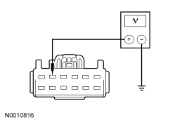
|
Yes GO to A2. No VERIFY battery junction box (BJB) fuse 32 (30A) is OK. If BJB fuse 32 (30A) is OK, REPAIR the circuit. TEST the system for normal operation. For vehicles equipped with seat side air bags, DISCONNECT the battery ground cable. DISCONNECT the restraint system diagnostic tool from driver seat side air bag module C327 and CONNECT driver seat side air bag module C327. REPOWER the SRS. REFER to Section 501-20B. |
| A2 CHECK CIRCUIT GD126 (BK/WH) FOR AN OPEN | |
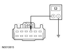
|
Yes INSTALL a new driver seat control switch. TEST the system for normal operation. For vehicles equipped with seat side air bags, DISCONNECT the battery ground cable. DISCONNECT the restraint system diagnostic tool from driver seat side air bag module C327 and CONNECT driver seat side air bag module C327. REPOWER the SRS. REFER to Section 501-20B. No REPAIR the circuit. TEST the system for normal operation. For vehicles equipped with seat side air bags, DISCONNECT the battery ground cable. DISCONNECT the restraint system diagnostic tool from driver seat side air bag module C327 and CONNECT driver seat side air bag module C327. REPOWER the SRS. REFER to Section 501-20B. |
Pinpoint Test B: The Power Seat Is Inoperative — Driver, Without Power Recliner
Refer to Wiring Diagrams Cell 120, Power Seats for schematic and connector information.
Normal Operation
The driver seat control switch is powered by battery voltage on circuit SBB32 (VT/RD) and is supplied ground on circuit GD126 (BK/WH). When pressed, the seat control switch supplies that voltage and ground to a power seat track motor to move the seat. When pressed in the opposite direction, the seat control switch reverses the polarity to that same power seat track motor, which moves the seat in the opposite direction. There are 3 power seat track motors that combine to move the seat cushion horizontally (forward/rearward) and vertically (front up/down and rear up/down). If a new seat track motor needs to be installed, it is necessary to install an entire power seat track.
Possible Causes
An inoperative driver power seat can be caused by:
- a fuse.
- wiring, terminals or connectors.
- a faulty seat control switch.
PINPOINT TEST B: THE POWER SEAT IS INOPERATIVE — DRIVER, WITHOUT POWER RECLINER
| Test Step | Result / Action to Take |
|---|---|
| B1 CHECK CIRCUIT SBB32 (VT/RD) FOR VOLTAGE | |
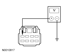
|
Yes GO to B2. No VERIFY battery junction box (BJB) fuse 32 (30A) is OK. If BJB fuse 32 (30A) is OK, REPAIR the circuit. TEST the system for normal operation. For vehicles equipped with seat side air bags, DISCONNECT the battery ground cable. DISCONNECT the restraint system diagnostic tool from driver seat side air bag module C327 and CONNECT driver seat side air bag module C327. REPOWER the SRS. REFER to Section 501-20B. |
| B2 CHECK CIRCUIT GD126 (BK/WH) FOR AN OPEN | |
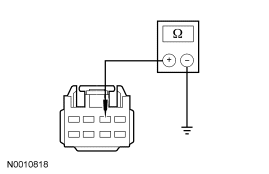
|
Yes INSTALL a new driver seat control switch. TEST the system for normal operation. For vehicles equipped with seat side air bags, DISCONNECT the battery ground cable. DISCONNECT the restraint system diagnostic tool from driver seat side air bag module C327 and CONNECT driver seat side air bag module C327. REPOWER the SRS. REFER to Section 501-20B. No REPAIR the circuit. TEST the system for normal operation. For vehicles equipped with seat side air bags, DISCONNECT the battery ground cable. DISCONNECT the restraint system diagnostic tool from driver seat side air bag module C327 and CONNECT driver seat side air bag module C327. REPOWER the SRS. REFER to Section 501-20B. |
Pinpoint Test C: The Power Seat Is Inoperative — Passenger
Refer to Wiring Diagrams Cell 120, Power Seats for schematic and connector information.
Normal Operation
The passenger seat control switch is powered by battery voltage on circuit SBB31 (WH/RD) and is supplied ground on circuit GD139 (BK/YE). When pressed, the seat control switch supplies that voltage and ground to a power seat track motor to move the seat. When pressed in the opposite direction, the seat control switch reverses the polarity to that same power seat track motor, which moves the seat in the opposite direction. There are 3 power seat track motors that combine to move the seat cushion horizontally (forward/rearward) and vertically (front up/down and rear up/down). If a new seat track motor needs to be installed, it is necessary to install an entire power seat track.
Possible Causes
An inoperative passenger power seat can be caused by:
- a fuse.
- wiring, terminals or connectors.
- a faulty seat control switch.
PINPOINT TEST C: THE POWER SEAT IS INOPERATIVE — PASSENGER
| Test Step | Result / Action to Take |
|---|---|
| C1 CHECK CIRCUIT SBB31 (WH/RD) FOR VOLTAGE | |
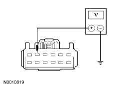
|
Yes GO to C2. No VERIFY battery junction box (BJB) fuse 31 (30A) is OK. If BJB fuse 31 (30A) is OK, REPAIR the circuit. TEST the system for normal operation. For vehicles equipped with seat side air bags, DISCONNECT the battery ground cable. DISCONNECT the restraint system diagnostic tool from passenger seat side air bag module C313 and CONNECT passenger seat side air bag module C313. REPOWER the SRS. REFER to Section 501-20B. |
| C2 CHECK CIRCUIT GD139 (BK/YE) FOR AN OPEN | |
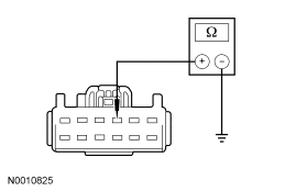
|
Yes INSTALL a new passenger seat control switch. TEST the system for normal operation. For vehicles equipped with seat side air bags, DISCONNECT the battery ground cable. DISCONNECT the restraint system diagnostic tool from passenger seat side air bag module C313 and CONNECT passenger seat side air bag module C313. REPOWER the SRS. REFER to Section 501-20B. No REPAIR the circuit. TEST the system for normal operation. For vehicles equipped with seat side air bags, DISCONNECT the battery ground cable. DISCONNECT the restraint system diagnostic tool from passenger seat side air bag module C313 and CONNECT passenger seat side air bag module C313. REPOWER the SRS. REFER to Section 501-20B. |
Pinpoint Test D: The Power Seat Moves But Is Loose
Normal Operation
The power seat movement should be smooth and the seat cushion should not rock during or after operation.
Possible Causes
A loose power seat can be caused by:
- loose fastening hardware.
- a faulty seat track component.
PINPOINT TEST D: THE POWER SEAT MOVES BUT IS LOOSE
| Test Step | Result / Action to Take |
|---|---|
| D1 CHECK THE FASTENING HARDWARE | |
|
Yes TIGHTEN all fastening hardware to specification. TEST the system for normal operation. For vehicles equipped with seat side air bags, DISCONNECT the battery ground cable. DISCONNECT the restraint system diagnostic tool from seat side air bag module C327 (driver) or C313 (passenger) and CONNECT seat side air bag module C327 (driver) or C313 (passenger). REPOWER the SRS. REFER to Section 501-20B. No IDENTIFY the cause and INSTALL a new seat track component. TEST the system for normal operation. For vehicles equipped with seat side air bags, DISCONNECT the battery ground cable. DISCONNECT the restraint system diagnostic tool from seat side air bag module C327 (driver) or C313 (passenger) and CONNECT seat side air bag module C327 (driver) or C313 (passenger). REPOWER the SRS. REFER to Section 501-20B. |
Pinpoint Test E: The Power Seat Moves But Is Noisy
Normal Operation
The power seat should move quietly during operation. Some noise is acceptable.
Possible Causes
A noisy power seat can be caused by:
- a misaligned seat track.
- a faulty seat track component.
- an object obstructing seat movement.
PINPOINT TEST E: THE POWER SEAT MOVES BUT IS NOISY
| Test Step | Result / Action to Take |
|---|---|
| E1 CHECK THE TRACK ALIGNMENT | |
|
Yes ALIGN the track to the seat and the floor. TEST the system for normal operation. For vehicles equipped with seat side air bags, DISCONNECT the battery ground cable. DISCONNECT the restraint system diagnostic tool from seat side air bag module C327 (driver) or C313 (passenger) and CONNECT seat side air bag module C327 (driver) or C313 (passenger). REPOWER the SRS. REFER to Section 501-20B. No INSTALL a new seat track part. TEST the system for normal operation. For vehicles equipped with seat side air bags, DISCONNECT the battery ground cable. DISCONNECT the restraint system diagnostic tool from seat side air bag module C327 (driver) or C313 (passenger) and CONNECT seat side air bag module C327 (driver) or C313 (passenger). REPOWER the SRS. REFER to Section 501-20B. |
Pinpoint Test F: The Power Seat Does Not Make Full Travel
Normal Operation
The power seat should travel fully horizontal (forward/rearward) and vertical (front up/down and rear up/down).
Possible Causes
A power seat that does not make full travel can be caused by:
- an obstruction.
- a faulty seat track component.
PINPOINT TEST F: THE POWER SEAT DOES NOT MAKE FULL TRAVEL
| Test Step | Result / Action to Take |
|---|---|
| F1 CHECK FOR AN OBSTRUCTION IN THE SEAT TRACK | |
|
Yes REMOVE the obstruction(s) and GREASE the track(s). TEST the system for normal operation. For vehicles equipped with seat side air bags, DISCONNECT the battery ground cable. DISCONNECT the restraint system diagnostic tool from seat side air bag module C327 (driver) or C313 (passenger) and CONNECT seat side air bag module C327 (driver) or C313 (passenger). REPOWER the SRS. REFER to Section 501-20B. No IDENTIFY the cause and INSTALL a new seat track component. TEST the system for normal operation. For vehicles equipped with seat side air bags, DISCONNECT the battery ground cable. DISCONNECT the restraint system diagnostic tool from seat side air bag module C327 (driver) or C313 (passenger) and CONNECT seat side air bag module C327 (driver) or C313 (passenger). REPOWER the SRS. REFER to Section 501-20B. |
Pinpoint Test G: The Power Seat Does Not Move Horizontally/Vertically/Recline — Driver
Refer to Wiring Diagrams Cell 120, Power Seats for schematic and connector information.
Normal Operation
The driver seat control switch is powered by battery voltage on circuit SBB32 (VT/RD) and is supplied ground on circuit GD126 (BK/WH). When pressed, the seat control switch supplies that voltage and ground to a power seat track motor or power recline motor to move the seat or backrest. When pressed in the opposite direction, the seat control switch reverses the polarity to that same power seat track motor or power recline motor, which moves the seat or backrest in the opposite direction. There are 3 power seat track motors that combine to move the seat cushion horizontally (forward/rearward) and vertically (front up/down and rear up/down). There is an additional motor in the power recline mechanism to move the seat backrest forward and rearward. If a new seat track motor needs to be installed, it is necessary to install an entire power seat track. The power recline motor is serviced separately.
Possible Causes
A driver power seat that does not move horizontally and/or vertically can be caused by:
- wiring, terminals or connectors.
- a faulty seat control switch.
- a faulty seat track motor (seat track).
- a faulty power recliner mechanism.
PINPOINT TEST G: THE POWER SEAT DOES NOT MOVE HORIZONTALLY/VERTICALLY/RECLINE — DRIVER
| Test Step | Result / Action to Take |
|---|---|
| G1 CHECK THE HORIZONTAL DIRECTION MOTOR FOR CORRECT OPERATION | |
|
Yes GO to G2. No GO to G3. |
| G2 CHECK THE RECLINER MOTOR FOR CORRECT OPERATION | |
|
Yes GO to G6. No GO to G13. |
| G3 CHECK THE VOLTAGE TO THE DRIVER SEAT HORIZONTAL MOTOR | |
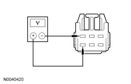
|
Yes INSTALL a new driver seat track assembly. TEST the system for normal operation. For vehicles equipped with seat side air bags, DISCONNECT the battery ground cable. DISCONNECT the restraint system diagnostic tool from driver seat side air bag module C327 and CONNECT driver seat side air bag module C327. REPOWER the SRS. REFER to Section 501-20B. No GO to G4. |
| G4 CHECK CIRCUIT CPS28 (GN) FOR AN OPEN AND SHORT TO GROUND | |
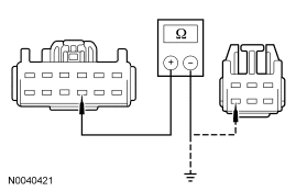
|
Yes GO to G5. No REPAIR the circuit. TEST the system for normal operation. For vehicles equipped with seat side air bags, DISCONNECT the battery ground cable. DISCONNECT the restraint system diagnostic tool from driver seat side air bag module C327 and CONNECT driver seat side air bag module C327. REPOWER the SRS. REFER to Section 501-20B. |
| G5 CHECK CIRCUIT CPS23 (GN/VT) FOR AN OPEN AND SHORT TO GROUND | |
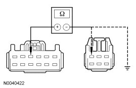
|
Yes INSTALL a new driver seat control switch. TEST the system for normal operation. For vehicles equipped with seat side air bags, DISCONNECT the battery ground cable. DISCONNECT the restraint system diagnostic tool from driver seat side air bag module C327 and CONNECT driver seat side air bag module C327. REPOWER the SRS. REFER to Section 501-20B. No REPAIR the circuit. TEST the system for normal operation. For vehicles equipped with seat side air bags, DISCONNECT the battery ground cable. DISCONNECT the restraint system diagnostic tool from driver seat side air bag module C327 and CONNECT driver seat side air bag module C327. REPOWER the SRS. REFER to Section 501-20B. |
| G6 DETERMINE THE SEAT TILTING FAILURE | |
|
Yes If only forward tilting operates, GO to G7 . If only rear tilting operates, GO to G10 . No INSTALL a new driver seat control switch. TEST the system for normal operation. For vehicles equipped with seat side air bags, DISCONNECT the battery ground cable. DISCONNECT the restraint system diagnostic tool from driver seat side air bag module C327 and CONNECT driver seat side air bag module C327. REPOWER the SRS. REFER to Section 501-20B. |
| G7 CHECK THE VOLTAGE TO THE DRIVER SEAT REAR HEIGHT MOTOR | |
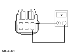
|
Yes INSTALL a new driver seat track assembly. TEST the system for normal operation. For vehicles equipped with seat side air bags, DISCONNECT the battery ground cable. DISCONNECT the restraint system diagnostic tool from driver seat side air bag module C327 and CONNECT driver seat side air bag module C327. REPOWER the SRS. REFER to Section 501-20B. No GO to G8. |
| G8 CHECK CIRCUIT CPS27 (BU/BN) FOR AN OPEN AND SHORT TO GROUND | |
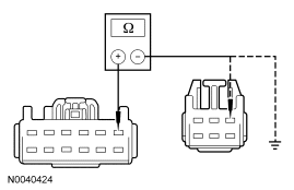
|
Yes GO to G9. No REPAIR the circuit. TEST the system for normal operation. For vehicles equipped with seat side air bags, DISCONNECT the battery ground cable. DISCONNECT the restraint system diagnostic tool from driver seat side air bag module C327 and CONNECT driver seat side air bag module C327. REPOWER the SRS. REFER to Section 501-20B. |
| G9 CHECK CIRCUIT CPS26 (YE/BU) FOR AN OPEN AND SHORT TO GROUND | |
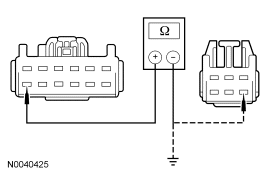
|
Yes INSTALL a new driver seat control switch. TEST the system for normal operation. For vehicles equipped with seat side air bags, DISCONNECT the battery ground cable. DISCONNECT the restraint system diagnostic tool from driver seat side air bag module C327 and CONNECT driver seat side air bag module C327. REPOWER the SRS. REFER to Section 501-20B. No REPAIR the circuit. TEST the system for normal operation. For vehicles equipped with seat side air bags, DISCONNECT the battery ground cable. DISCONNECT the restraint system diagnostic tool from driver seat side air bag module C327 and CONNECT driver seat side air bag module C327. REPOWER the SRS. REFER to Section 501-20B. |
| G10 CHECK THE VOLTAGE TO DRIVER SEAT FRONT HEIGHT MOTOR | |
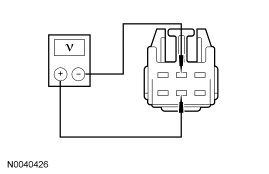
|
Yes INSTALL a new driver seat track assembly. TEST the system for normal operation. For vehicles equipped with seat side air bags, DISCONNECT the battery ground cable. DISCONNECT the restraint system diagnostic tool from driver seat side air bag module C327 and CONNECT driver seat side air bag module C327. REPOWER the SRS. REFER to Section 501-20B. No GO to G11. |
| G11 CHECK CIRCUIT CPS25 (WH/VT) FOR AN OPEN AND SHORT TO GROUND | |
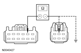
|
Yes GO to G12. No REPAIR the circuit. TEST the system for normal operation. For vehicles equipped with seat side air bags, DISCONNECT the battery ground cable. DISCONNECT the restraint system diagnostic tool from driver seat side air bag module C327 and CONNECT driver seat side air bag module C327. REPOWER the SRS. REFER to Section 501-20B. |
| G12 CHECK CIRCUIT CPS24 (GY) FOR AN OPEN | |
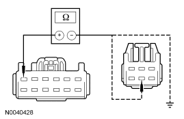
|
Yes INSTALL a new driver seat control switch. TEST the system for normal operation. For vehicles equipped with seat side air bags, DISCONNECT the battery ground cable. DISCONNECT the restraint system diagnostic tool from driver seat side air bag module C327 and CONNECT driver seat side air bag module C327. REPOWER the SRS. REFER to Section 501-20B. No REPAIR the circuit. TEST the system for normal operation. For vehicles equipped with seat side air bags, DISCONNECT the battery ground cable. DISCONNECT the restraint system diagnostic tool from driver seat side air bag module C327 and CONNECT driver seat side air bag module C327. REPOWER the SRS. REFER to Section 501-20B. |
| G13 CHECK VOLTAGE TO THE DRIVER SEAT RECLINER MOTOR | |
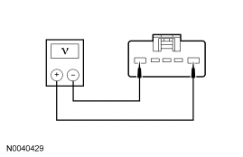
|
Yes INSTALL a new driver seat recliner motor. TEST the system for normal operation. For vehicles equipped with seat side air bags, DISCONNECT the battery ground cable. DISCONNECT the restraint system diagnostic tool from driver seat side air bag module C327 and CONNECT driver seat side air bag module C327. REPOWER the SRS. REFER to Section 501-20B. No GO to G14. |
| G14 CHECK CIRCUIT CPS29 (WH/BN) FOR AN OPEN AND SHORT TO GROUND | |
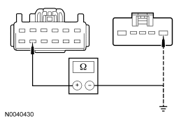
|
Yes GO to G15. No REPAIR the circuit. TEST the system for normal operation. For vehicles equipped with seat side air bags, DISCONNECT the battery ground cable. DISCONNECT the restraint system diagnostic tool from driver seat side air bag module C327 and CONNECT driver seat side air bag module C327. REPOWER the SRS. REFER to Section 501-20B. |
| G15 CHECK CIRCUIT CPS30 (VT/BN) FOR AN OPEN AND SHORT TO GROUND | |
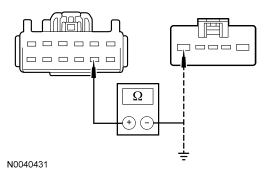
|
Yes INSTALL a new driver seat control switch. TEST the system for normal operation. For vehicles equipped with seat side air bags, DISCONNECT the battery ground cable. DISCONNECT the restraint system diagnostic tool from driver seat side air bag module C327 and CONNECT driver seat side air bag module C327. REPOWER the SRS. REFER to Section 501-20B. No REPAIR the circuit. TEST the system for normal operation. For vehicles equipped with seat side air bags, DISCONNECT the battery ground cable. DISCONNECT the restraint system diagnostic tool from driver seat side air bag module C327 and CONNECT driver seat side air bag module C327. REPOWER the SRS. REFER to Section 501-20B. |
Pinpoint Test H: The Power Seat Does Not Move Horizontally/Vertically — Driver
Refer to Wiring Diagrams Cell 120, Power Seats for schematic and connector information.
Normal Operation
The driver seat control switch is powered by battery voltage on circuit SBB32 (VT/RD) and is supplied ground on circuit GD126 (BK/WH). When pressed, the seat control switch supplies that voltage and ground to a power seat track motor to move the seat. When pressed in the opposite direction, the seat control switch reverses the polarity to that same power seat track motor, which moves the seat in the opposite direction. There are 3 power seat track motors that combine to move the seat cushion horizontally (forward/rearward) and vertically (front up/down and rear up/down). If a new motor needs to be installed, it is necessary to install an entire power seat track.
Possible Causes
A driver power seat that does not move horizontally and/or vertically can be caused by:
- wiring, terminals or connectors.
- a faulty seat control switch.
- a faulty seat track motor (seat track).
PINPOINT TEST H: THE POWER SEAT DOES NOT MOVE HORIZONTALLY/VERTICALLY — DRIVER
| Test Step | Result / Action to Take |
|---|---|
| H1 CHECK HORIZONTAL DIRECTION MOTOR FOR CORRECT OPERATION | |
|
Yes GO to H5. No GO to H2. |
| H2 CHECK VOLTAGE TO THE DRIVER SEAT HORIZONTAL MOTOR | |
|
Yes INSTALL a new driver seat track assembly. TEST the system for normal operation. For vehicles equipped with seat side air bags, DISCONNECT the battery ground cable. DISCONNECT the restraint system diagnostic tool from driver seat side air bag module C327 and CONNECT driver seat side air bag module C327. REPOWER the SRS. REFER to Section 501-20B. No GO to H3. |
| H3 CHECK CIRCUIT CPS22 (BN) FOR AN OPEN AND SHORT TO GROUND | |
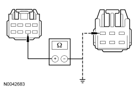
|
Yes GO to H4. No REPAIR the circuit. TEST the system for normal operation. For vehicles equipped with seat side air bags, DISCONNECT the battery ground cable. DISCONNECT the restraint system diagnostic tool from driver seat side air bag module C327 and CONNECT driver seat side air bag module C327. REPOWER the SRS. REFER to Section 501-20B. |
| H4 CHECK CIRCUIT CPS23 (GN/VT) FOR AN OPEN AND SHORT TO GROUND | |
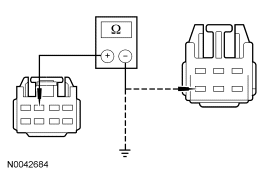
|
Yes INSTALL a new driver seat control switch. TEST the system for normal operation. For vehicles equipped with seat side air bags, DISCONNECT the battery ground cable. DISCONNECT the restraint system diagnostic tool from driver seat side air bag module C327 and CONNECT driver seat side air bag module C327. REPOWER the SRS. REFER to Section 501-20B. No REPAIR the circuit. TEST the system for normal operation. For vehicles equipped with seat side air bags, DISCONNECT the battery ground cable. DISCONNECT the restraint system diagnostic tool from driver seat side air bag module C327 and CONNECT driver seat side air bag module C327. REPOWER the SRS. REFER to Section 501-20B. |
| H5 DETERMINE SEAT TILTING FAILURE | |
|
Yes If only forward tilting operates, GO to H6 . If only rear tilting operates, GO to H9 . No INSTALL a new driver seat control switch. TEST the system for normal operation. For vehicles equipped with seat side air bags, DISCONNECT the battery ground cable. DISCONNECT the restraint system diagnostic tool from driver seat side air bag module C327 and CONNECT driver seat side air bag module C327. REPOWER the SRS. REFER to Section 501-20B. |
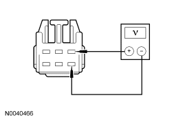
| H6 CHECK VOLTAGE TO THE DRIVER SEAT REAR HEIGHT MOTOR | |
|
Yes INSTALL a new driver seat track assembly. TEST the system for normal operation. For vehicles equipped with seat side air bags, DISCONNECT the battery ground cable. DISCONNECT the restraint system diagnostic tool from driver seat side air bag module C327 and CONNECT driver seat side air bag module C327. REPOWER the SRS. REFER to Section 501-20B. No GO to H7. |
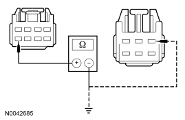
| H7 CHECK CIRCUIT CPS27 (BU/BN) FOR AN OPEN AND SHORT TO GROUND | |
|
Yes GO to H8. No REPAIR the circuit. TEST the system for normal operation. For vehicles equipped with seat side air bags, DISCONNECT the battery ground cable. DISCONNECT the restraint system diagnostic tool from driver seat side air bag module C327 and CONNECT driver seat side air bag module C327. REPOWER the SRS. REFER to Section 501-20B. |
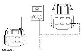
| H8 CHECK CIRCUIT CPS26 (YE/BU) FOR AN OPEN AND SHORT TO GROUND | |
|
Yes INSTALL a new driver seat control switch. TEST the system for normal operation. For vehicles equipped with seat side air bags, DISCONNECT the battery ground cable. DISCONNECT the restraint system diagnostic tool from driver seat side air bag module C327 and CONNECT driver seat side air bag module C327. REPOWER the SRS. REFER to Section 501-20B. No REPAIR the circuit. TEST the system for normal operation. For vehicles equipped with seat side air bags, DISCONNECT the battery ground cable. DISCONNECT the restraint system diagnostic tool from driver seat side air bag module C327 and CONNECT driver seat side air bag module C327. REPOWER the SRS. REFER to Section 501-20B. |
| H9 CHECK THE VOLTAGE TO THE DRIVER SEAT FRONT HEIGHT MOTOR | |
|
Yes INSTALL a new driver seat track assembly. TEST the system for normal operation. For vehicles equipped with seat side air bags, DISCONNECT the battery ground cable. DISCONNECT the restraint system diagnostic tool from driver seat side air bag module C327 and CONNECT driver seat side air bag module C327. REPOWER the SRS. REFER to Section 501-20B. No GO to H10. |
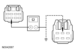
| H10 CHECK CIRCUIT CPS25 (WH/VT) FOR AN OPEN AND SHORT TO GROUND | |
|
Yes GO to H11. No REPAIR the circuit. TEST the system for normal operation. For vehicles equipped with seat side air bags, DISCONNECT the battery ground cable. DISCONNECT the restraint system diagnostic tool from driver seat side air bag module C327 and CONNECT driver seat side air bag module C327. REPOWER the SRS. REFER to Section 501-20B. |
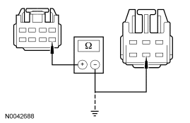
| H11 CHECK CIRCUIT CPS24 (GY) FOR AN OPEN | |
|
Yes INSTALL a new driver seat control switch. TEST the system for normal operation. For vehicles equipped with seat side air bags, DISCONNECT the battery ground cable. DISCONNECT the restraint system diagnostic tool from driver seat side air bag module C327 and CONNECT driver seat side air bag module C327. REPOWER the SRS. REFER to Section 501-20B. No REPAIR the circuit. TEST the system for normal operation. For vehicles equipped with seat side air bags, DISCONNECT the battery ground cable. DISCONNECT the restraint system diagnostic tool from driver seat side air bag module C327 and CONNECT driver seat side air bag module C327. REPOWER the SRS. REFER to Section 501-20B. |
Pinpoint Test I: The Power Seat Does Not Move Horizontally/Vertically/Recline — Passenger
Refer to Wiring Diagrams Cell 120, Power Seats for schematic and connector information.
Normal Operation
The passenger seat control switch is powered by battery voltage on circuit SBB31 (WH/RD) and is supplied ground on circuit GD139 (BK/YE). When pressed, the seat control switch supplies that voltage and ground to a power seat track motor or power recline motor to move the seat or backrest. When pressed in the opposite direction, the seat control switch reverses the polarity to that same power seat track motor or power recline motor, which moves the seat or backrest in the opposite direction. There are 3 power seat track motors that combine to move the seat cushion horizontally (forward/rearward) and vertically (front up/down and rear up/down). There is an additional motor in the power recline mechanism to move the seat backrest forward and rearward. If a new seat track motor needs to be installed, it is necessary to install an entire power seat track. The power recline motor is serviced separately.
Possible Causes
A passenger power seat that does not move horizontally and/or vertically can be caused by:
- wiring, terminals or connectors.
- a faulty seat control switch.
- a faulty seat track motor (seat track).
- a faulty power recliner mechanism.
PINPOINT TEST I: THE POWER SEAT DOES NOT MOVE HORIZONTALLY/VERTICALLY/RECLINE — PASSENGER
| Test Step | Result / Action to Take |
|---|---|
| I1 CHECK THE HORIZONTAL DIRECTION MOTOR FOR CORRECT OPERATION | |
|
Yes GO to I2. No GO to I3. |
| I2 CHECK THE RECLINER MOTOR FOR CORRECT OPERATION | |
|
Yes GO to I6. No GO to I13. |
| I3 CHECK THE VOLTAGE TO THE PASSENGER SEAT HORIZONTAL MOTOR | |
|
Yes INSTALL a new passenger seat track assembly. TEST the system for normal operation. For vehicles equipped with seat side air bags, DISCONNECT the battery ground cable. DISCONNECT the restraint system diagnostic tool from passenger seat side air bag module C313 and CONNECT passenger seat side air bag module C313. REPOWER the SRS. REFER to Section 501-20B. No GO to I4. |
| I4 CHECK CIRCUIT CPS38 (GN/BU) FOR AN OPEN AND SHORT TO GROUND | |
|
Yes GO to I5. No REPAIR the circuit. TEST the system for normal operation. For vehicles equipped with seat side air bags, DISCONNECT the battery ground cable. DISCONNECT the restraint system diagnostic tool from passenger seat side air bag module C313 and CONNECT passenger seat side air bag module C313. REPOWER the SRS. REFER to Section 501-20B. |
| I5 CHECK CIRCUIT CPS33 (WH) FOR AN OPEN AND SHORT TO GROUND | |
|
Yes INSTALL a new passenger seat control switch. TEST the system for normal operation. For vehicles equipped with seat side air bags, DISCONNECT the battery ground cable. DISCONNECT the restraint system diagnostic tool from passenger seat side air bag module C313 and CONNECT passenger seat side air bag module C313. REPOWER the SRS. REFER to Section 501-20B. No REPAIR the circuit. TEST the system for normal operation. For vehicles equipped with seat side air bags, DISCONNECT the battery ground cable. DISCONNECT the restraint system diagnostic tool from passenger seat side air bag module C313 and CONNECT passenger seat side air bag module C313. REPOWER the SRS. REFER to Section 501-20B. |
| I6 DETERMINE THE SEAT TILTING FAILURE | |
|
Yes If only forward tilting operates, GO to I7 . If only rear tilting operates, GO to I10 . No INSTALL a new passenger seat control switch. TEST the system for normal operation. For vehicles equipped with seat side air bags, DISCONNECT the battery ground cable. DISCONNECT the restraint system diagnostic tool from passenger seat side air bag module C313 and CONNECT passenger seat side air bag module C313. REPOWER the SRS. REFER to Section 501-20B. |
| I7 CHECK THE VOLTAGE TO THE PASSENGER SEAT REAR HEIGHT MOTOR | |
|
Yes INSTALL a new passenger seat track assembly. TEST the system for normal operation. For vehicles equipped with seat side air bags, DISCONNECT the battery ground cable. DISCONNECT the restraint system diagnostic tool from passenger seat side air bag module C313 and CONNECT passenger seat side air bag module C313. REPOWER the SRS. REFER to Section 501-20B. No GO to I8. |
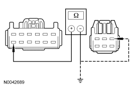
| I8 CHECK CIRCUIT CPS37 (WH/BU) FOR AN OPEN AND SHORT TO GROUND | |
|
Yes GO to I9. No REPAIR the circuit. TEST the system for normal operation. For vehicles equipped with seat side air bags, DISCONNECT the battery ground cable. DISCONNECT the restraint system diagnostic tool from passenger seat side air bag module C313 and CONNECT passenger seat side air bag module C313. REPOWER the SRS. REFER to Section 501-20B. |
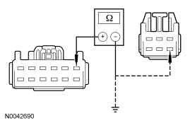
| I9 CHECK CIRCUIT CPS36 (YE/GY) FOR AN OPEN AND SHORT TO GROUND | |
|
Yes INSTALL a new passenger seat control switch. TEST the system for normal operation. For vehicles equipped with seat side air bags, DISCONNECT the battery ground cable. DISCONNECT the restraint system diagnostic tool from passenger seat side air bag module C313 and CONNECT passenger seat side air bag module C313. REPOWER the SRS. REFER to Section 501-20B. No REPAIR the circuit. TEST the system for normal operation. For vehicles equipped with seat side air bags, DISCONNECT the battery ground cable. DISCONNECT the restraint system diagnostic tool from passenger seat side air bag module C313 and CONNECT passenger seat side air bag module C313. REPOWER the SRS. REFER to Section 501-20B. |
| I10 CHECK THE VOLTAGE TO PASSENGER SEAT FRONT HEIGHT MOTOR | |
|
Yes INSTALL a new passenger seat track assembly. TEST the system for normal operation. For vehicles equipped with seat side air bags, DISCONNECT the battery ground cable. DISCONNECT the restraint system diagnostic tool from passenger seat side air bag module C313 and CONNECT passenger seat side air bag module C313. REPOWER the SRS. REFER to Section 501-20B. No GO to I11. |
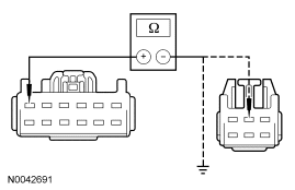
| I11 CHECK CIRCUIT CPS35 (VT/GN) FOR AN OPEN AND SHORT TO GROUND | |
|
Yes GO to I12. No REPAIR the circuit. TEST the system for normal operation. For vehicles equipped with seat side air bags, DISCONNECT the battery ground cable. DISCONNECT the restraint system diagnostic tool from passenger seat side air bag module C313 and CONNECT passenger seat side air bag module C313. REPOWER the SRS. REFER to Section 501-20B. |
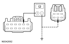
| I12 CHECK CIRCUIT CPS34 (GY/BU) FOR AN OPEN | |
|
Yes INSTALL a new passenger seat control switch. TEST the system for normal operation. For vehicles equipped with seat side air bags, DISCONNECT the battery ground cable. DISCONNECT the restraint system diagnostic tool from passenger seat side air bag module C313 and CONNECT passenger seat side air bag module C313. REPOWER the SRS. REFER to Section 501-20B. No REPAIR the circuit. TEST the system for normal operation. For vehicles equipped with seat side air bags, DISCONNECT the battery ground cable. DISCONNECT the restraint system diagnostic tool from passenger seat side air bag module C313 and CONNECT passenger seat side air bag module C313. REPOWER the SRS. REFER to Section 501-20B. |
| I13 CHECK VOLTAGE TO THE PASSENGER SEAT RECLINER MOTOR | |
|
Yes INSTALL a new passenger seat recliner motor. TEST the system for normal operation. For vehicles equipped with seat side air bags, DISCONNECT the battery ground cable. DISCONNECT the restraint system diagnostic tool from passenger seat side air bag module C313 and CONNECT passenger seat side air bag module C313. REPOWER the SRS. REFER to Section 501-20B. No GO to I14. |
| I14 CHECK CIRCUIT CPS39 (GY/YE) FOR AN OPEN AND SHORT TO GROUND | |
|
Yes GO to I15. No REPAIR the circuit. TEST the system for normal operation. For vehicles equipped with seat side air bags, DISCONNECT the battery ground cable. DISCONNECT the restraint system diagnostic tool from passenger seat side air bag module C313 and CONNECT passenger seat side air bag module C313. REPOWER the SRS. REFER to Section 501-20B. |
| I15 CHECK CIRCUIT CPS40 (VT/GY) FOR AN OPEN AND SHORT TO GROUND | |
|
Yes INSTALL a new passenger seat control switch. TEST the system for normal operation. DISCONNECT the battery ground cable. DISCONNECT the restraint system diagnostic tool from passenger seat side air bag module C313 and CONNECT passenger seat side air bag module C313. REPOWER the SRS. REFER to Section 501-20B. No REPAIR the circuit. TEST the system for normal operation. For vehicles equipped with seat side air bags, DISCONNECT the battery ground cable. DISCONNECT the restraint system diagnostic tool from passenger seat side air bag module C313 and CONNECT passenger seat side air bag module C313. REPOWER the SRS. REFER to Section 501-20B. |
Pinpoint Test J: The Memory Seat Is Inoperative
Refer to Wiring Diagrams Cell 123, Memory Seats for schematic and connector information.
Refer to Wiring Diagrams Cell 149, Component Testing for schematic and connector information.
Normal Operation
The driver seat control switch is powered by battery voltage on circuit SBB15 (WH/RD) and is supplied ground on circuit GD126 (BK/WH). When pressed, the seat control switch supplies the voltage and ground to the applicable driver seat module (DSM) inputs. The DSM then supplies voltage and ground to the appropriate power seat track motor or power recline motor based on the inputs received from the seat control switch. When pressed in the opposite direction, the seat control switch reverses the polarity to the DSM inputs, and the DSM likewise reverses polarity of the appropriate power seat track motor or power recliner motor circuits causing the seat or backrest to move in the opposite direction. There are 3 power seat track motors that combine to move the seat horizontally (forward/rearward) and vertically (front up/down and rear up/down). The seat backrest power recliner mechanism uses a single motor to move the seat backrest forward and rearward.
Battery voltage is also supplied to DSM on circuit SBB15 (WH/RD) and SBB32 (VT/RD). Ground is supplied to the DSM on circuit GD126 (BK/WH).
Each motor, in the memory power seat track and power recliner mechanism contains a Hall-effect position sensor. The DSM supplies a signal feed circuit to each position sensor and a shared reference signal return circuit. Each position sensor sends a signal voltage back to the DSM used to monitor the position of the power seat and seat backrest. The DSM uses this information to return the seat to a stored pre-programmed position when pressing the memory seat position switch or a remote entry transmitter. The memory seat position switch is hard-wired to the driver door module (DDM) and communicates memory SET commands to the DSM via MS-CAN. Refer to Principles of Operation in this section or the owner's literature for information on programming the DDM for storing memory seat positions.
The following pinpoint test diagnoses a memory seat that does not operate in one or more directions when using the seat control switch. If the memory seat moves in all directions using the seat control switch, Go To Pinpoint Test K.
Possible Causes
An inoperative memory seat can be caused by:
- a fuse.
- wiring, terminals or connectors.
- a faulty seat control switch.
- a faulty power seat track.
- a faulty power recliner motor.
- a faulty DSM.
PINPOINT TEST J: THE MEMORY SEAT IS INOPERATIVE
| Test Step | Result / Action to Take | |||||||||||||||||||||||||||
|---|---|---|---|---|---|---|---|---|---|---|---|---|---|---|---|---|---|---|---|---|---|---|---|---|---|---|---|---|
| J1 RETRIEVE THE DTCs | ||||||||||||||||||||||||||||
|
Yes If DTCs B1663, B1664, B1665 and B1666 are all retrieved, GO to J10 . If DTC B1663, GO to J20 . If DTC B1664, GO to J23 . If DTC B1665, GO to J26 . If DTC B1666, GO to J29 . If DTC B1703, GO to J3 . If DTC B1707, GO to J3 . If DTC B1711, GO to J3 . If DTC B1715, GO to J3 . If DTC B1719, GO to J3 . If DTC B1723, GO to J3 . If DTC B1727, GO to J3 . If DTC B1731, GO to J3 . If DTC B1342, INSTALL a new DSM. REFER to Section 419-10. CARRY OUT programmable module installation (PMI). REFER to Section 418-01. REPEAT the self-test. CLEAR the DTCs. For vehicles equipped with seat side air bags, DISCONNECT the battery ground cable. DISCONNECT the restraint system diagnostic tool from driver seat side air bag module C327 and CONNECT driver seat side air bag module C327. REPOWER the SRS. REFER to Section 501-20B. No GO to J2. | |||||||||||||||||||||||||||
| J2 MONITOR THE DSM PIDs AND CHECK FOR CORRECT MEMORY SEAT SWITCH INPUTS | ||||||||||||||||||||||||||||
|
Yes GO to J9. No VERIFY battery junction box (BJB) fuse 15 (10A) is OK. If BJB fuse 15 (10A) fails while operating the seat control switch, DISCONNECT the seat control switch C3297 and GO to J7 . If BJB fuse 15 (10A) is OK, GO to J3 . | |||||||||||||||||||||||||||
| J3 CHECK THE SEAT CONTROL SWITCH | ||||||||||||||||||||||||||||
|
Yes GO to J4. No INSTALL a new seat control switch. REFER to Seat Control Switch in this section. REPEAT the self-test. CLEAR the DTCs. For vehicles equipped with seat side air bags, DISCONNECT the battery ground cable. DISCONNECT the restraint system diagnostic tool from driver seat side air bag module C327 and CONNECT driver seat side air bag module C327. REPOWER the SRS. REFER to Section 501-20B. | |||||||||||||||||||||||||||
| J4 CHECK CIRCUIT SBB15 (WH/RD) FOR VOLTAGE TO THE SEAT CONTROL SWITCH | ||||||||||||||||||||||||||||
|
Yes GO to J5. No VERIFY battery junction box (BJB) fuse 15 (10A) is OK. If BJB fuse 15 (10A) is OK, REPAIR the circuit. REPEAT the self-test. CLEAR the DTCs. For vehicles equipped with seat side air bags, DISCONNECT the battery ground cable. DISCONNECT the restraint system diagnostic tool from driver seat side air bag module C327 and CONNECT driver seat side air bag module C327. REPOWER the SRS. REFER to Section 501-20B. | |||||||||||||||||||||||||||
| J5 CHECK CIRCUIT GD126 (BK/WH) FOR AN OPEN | ||||||||||||||||||||||||||||
|
Yes GO to J6. No REPAIR the circuit. REPEAT the self-test. CLEAR the DTCs. For vehicles equipped with seat side air bags, DISCONNECT the battery ground cable. DISCONNECT the restraint system diagnostic tool from driver seat side air bag module C327 and CONNECT driver seat side air bag module C327. REPOWER the SRS. REFER to Section 501-20B. | |||||||||||||||||||||||||||
| J6 CHECK SEAT CONTROL SWITCH TO DRIVER SEAT MODULE CIRCUITS FOR A SHORT TO POWER | ||||||||||||||||||||||||||||
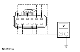
|
Yes REPAIR the affected circuit. REPEAT the self-test. CLEAR the DTCs. No GO to J7. For vehicles equipped with seat side air bags, DISCONNECT the battery ground cable. DISCONNECT the restraint system diagnostic tool from driver seat side air bag module C327 and CONNECT driver seat side air bag module C327. REPOWER the SRS. REFER to Section 501-20B. | |||||||||||||||||||||||||||
| J7 CHECK SEAT CONTROL SWITCH TO DRIVER SEAT MODULE CIRCUITS FOR A SHORT TO GROUND | ||||||||||||||||||||||||||||
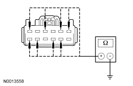
|
Yes REPAIR the affected circuit. REPEAT the self-test. CLEAR the DTCs. For vehicles equipped with seat side air bags, DISCONNECT the battery ground cable. DISCONNECT the restraint system diagnostic tool from driver seat side air bag module C327 and CONNECT driver seat side air bag module C327. REPOWER the SRS. REFER to Section 501-20B. No GO to J8. | |||||||||||||||||||||||||||
| J8 CHECK SEAT CONTROL SWITCH TO DRIVER SEAT MODULE CIRCUITS FOR AN OPEN | ||||||||||||||||||||||||||||
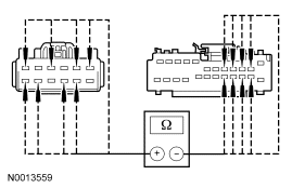
|
Yes INSTALL a new DSM. REFER to Section 419-10. CARRY OUT programmable module installation (PMI). REFER to Section 418-01. REPEAT the self-test. CLEAR the DTCs. DISCONNECT the battery ground cable. For vehicles equipped with seat side air bags, DISCONNECT the battery ground cable. DISCONNECT the restraint system diagnostic tool from driver seat side air bag module C327 and CONNECT driver seat side air bag module C327. REPOWER the SRS. REFER to Section 501-20B. No REPAIR the affected circuit. REPEAT the self-test. CLEAR the DTCs. For vehicles equipped with seat side air bags, DISCONNECT the battery ground cable. DISCONNECT the restraint system diagnostic tool from driver seat side air bag module C327 and CONNECT driver seat side air bag module C327. REPOWER the SRS. REFER to Section 501-20B. | |||||||||||||||||||||||||||
| J9 CHECK THE DSM FOR CORRECT OUTPUTS USING A DIAGNOSTIC TOOL AND DSM ACTIVE COMMANDS | ||||||||||||||||||||||||||||
|
Yes INSTALL a new DSM. REFER to Section 419-10. CARRY OUT programmable module installation (PMI). REFER to Section 418-01. REPEAT the self-test. CLEAR the DTCs. For vehicles equipped with seat side air bags, DISCONNECT the battery ground cable. DISCONNECT the restraint system diagnostic tool from driver seat side air bag module C327 and CONNECT driver seat side air bag module C327. REPOWER the SRS. REFER to Section 501-20B. No If no seat movement, GO to J10 . If no front vertical seat movement, GO to J20 . If no rear vertical seat movement, GO to J23 . If no horizontal seat movement, GO to J26 . If no recline seat movement, GO to J29 . | |||||||||||||||||||||||||||
| J10 CHECK DSM CIRCUIT SBB32 (VT/RD) FOR VOLTAGE | ||||||||||||||||||||||||||||
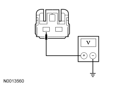
|
Yes GO to J11. No VERIFY battery junction box (BJB) fuse 32 (30A) is OK. If OK, REPAIR the circuit. REPEAT the self-test. CLEAR the DTCs. For vehicles equipped with seat side air bags, DISCONNECT the battery ground cable. DISCONNECT the restraint system diagnostic tool from driver seat side air bag module C327 and CONNECT driver seat side air bag module C327. REPOWER the SRS. REFER to Section 501-20B. | |||||||||||||||||||||||||||
| J11 CHECK CIRCUIT GD126 (BK/WH) FOR AN OPEN | ||||||||||||||||||||||||||||
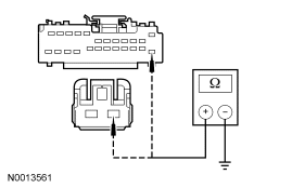
|
Yes GO to J12. No REPAIR the affected circuit. REPEAT the self-test. CLEAR the DTCs. For vehicles equipped with seat side air bags, DISCONNECT the battery ground cable. DISCONNECT the restraint system diagnostic tool from driver seat side air bag module C327 and CONNECT driver seat side air bag module C327. REPOWER the SRS. REFER to Section 501-20B. | |||||||||||||||||||||||||||
| J12 CHECK CIRCUITS CPS24 (GY) AND CPS25 (WH/VT) FOR A SHORT TO GROUND | ||||||||||||||||||||||||||||
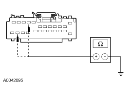
|
Yes GO to J14. No GO to J13. | |||||||||||||||||||||||||||
| J13 CHECK FRONT HEIGHT POWER SEAT MOTOR CIRCUITS CPS25 (WH/VT) AND CPS24 (GY) FOR A SHORT TO GROUND | ||||||||||||||||||||||||||||
|
Yes INSTALL a new driver seat track assembly. REFER to Seat Track in this section. REPEAT the self-test. CLEAR the DTCs. For vehicles equipped with seat side air bags, DISCONNECT the battery ground cable. DISCONNECT the restraint system diagnostic tool from driver seat side air bag module C327 and CONNECT driver seat side air bag module C327. REPOWER the SRS. REFER to Section 501-20B. No REPAIR the affected circuit. REPEAT the self-test. CLEAR the DTCs. For vehicles equipped with seat side air bags, DISCONNECT the battery ground cable. DISCONNECT the restraint system diagnostic tool from driver seat side air bag module C327 and CONNECT driver seat side air bag module C327. REPOWER the SRS. REFER to Section 501-20B. | |||||||||||||||||||||||||||
| J14 CHECK CIRCUITS CPS27 (BU/BN) AND CPS26 (YE/BU) FOR A SHORT TO GROUND | ||||||||||||||||||||||||||||
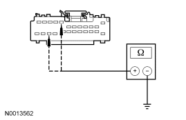
|
Yes GO to J16. No GO to J15. | |||||||||||||||||||||||||||
| J15 CHECK THE REAR HEIGHT POWER SEAT MOTOR CIRCUITS CPS27 (BU/BN) AND CPS26 (YE/BU) FOR A SHORT TO GROUND | ||||||||||||||||||||||||||||
|
Yes INSTALL a new driver seat track assembly. REFER to Seat Track in this section. REPEAT the self-test. CLEAR the DTCs. For vehicles equipped with seat side air bags, DISCONNECT the battery ground cable. DISCONNECT the restraint system diagnostic tool from driver seat side air bag module C327 and CONNECT driver seat side air bag module C327. REPOWER the SRS. REFER to Section 501-20B. No REPAIR the affected circuit. REPEAT the self-test. CLEAR the DTCs. For vehicles equipped with seat side air bags, DISCONNECT the battery ground cable. DISCONNECT the restraint system diagnostic tool from driver seat side air bag module C327 and CONNECT driver seat side air bag module C327. REPOWER the SRS. REFER to Section 501-20B. | |||||||||||||||||||||||||||
| J16 CHECK CIRCUITS CPS23 (GN/VT) AND CPS22 (BN) FOR A SHORT TO GROUND | ||||||||||||||||||||||||||||
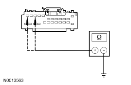
|
Yes GO to J18. No GO to J17. | |||||||||||||||||||||||||||
| J17 CHECK THE HORIZONTAL POWER SEAT MOTOR CIRCUITS CPS23 (GN/VT) AND CPS22 (BN) FOR A SHORT TO GROUND | ||||||||||||||||||||||||||||
|
Yes INSTALL a new driver seat track assembly. REFER to Seat Track in this section. REPEAT the self-test. CLEAR the DTCs. For vehicles equipped with seat side air bags, DISCONNECT the battery ground cable. DISCONNECT the restraint system diagnostic tool from driver seat side air bag module C327 and CONNECT driver seat side air bag module C327. REPOWER the SRS. REFER to Section 501-20B. No REPAIR the affected circuit. REPEAT the self-test. CLEAR the DTCs. For vehicles equipped with seat side air bags, DISCONNECT the battery ground cable. DISCONNECT the restraint system diagnostic tool from driver seat side air bag module C327 and CONNECT driver seat side air bag module C327. REPOWER the SRS. REFER to Section 501-20B. | |||||||||||||||||||||||||||
| J18 CHECK CIRCUITS CPS29 (WH/BN) AND CPS30 (VT/BN) FOR A SHORT TO GROUND | ||||||||||||||||||||||||||||
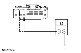
|
Yes INSTALL a new DSM. REFER to Section 419-10. CARRY OUT programmable module installation (PMI). REFER to Section 418-01. REPEAT the self-test. CLEAR the DTCs. For vehicles equipped with seat side air bags, DISCONNECT the battery ground cable. DISCONNECT the restraint system diagnostic tool from driver seat side air bag module C327 and CONNECT driver seat side air bag module C327. REPOWER the SRS. REFER to Section 501-20B. No GO to J19. | |||||||||||||||||||||||||||
| J19 CHECK THE DRIVER POWER SEAT RECLINER MOTOR CIRCUITS CPS29 (WH/BN) AND CPS30 (VT/BN) FOR A SHORT TO GROUND | ||||||||||||||||||||||||||||
|
Yes INSTALL a new driver seat recliner motor. REFER to Seat Recliner Motor in this section. REPEAT the self-test. CLEAR the DTCs. For vehicles equipped with seat side air bags, DISCONNECT the battery ground cable. DISCONNECT the restraint system diagnostic tool from driver seat side air bag module C327 and CONNECT driver seat side air bag module C327. REPOWER the SRS. REFER to Section 501-20B. No REPAIR the affected circuit. REPEAT the self-test. CLEAR the DTCs. For vehicles equipped with seat side air bags, DISCONNECT the battery ground cable. DISCONNECT the restraint system diagnostic tool from driver seat side air bag module C327 and CONNECT driver seat side air bag module C327. REPOWER the SRS. REFER to Section 501-20B. | |||||||||||||||||||||||||||
| J20 CHECK THE FRONT HEIGHT POWER SEAT MOTOR FOR CORRECT OPERATION | ||||||||||||||||||||||||||||
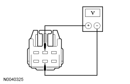
|
Yes INSTALL a new driver seat track assembly. REFER to Seat Track in this section. REPEAT the self-test. CLEAR the DTCs. For vehicles equipped with seat side air bags, DISCONNECT the battery ground cable. DISCONNECT the restraint system diagnostic tool from driver seat side air bag module C327 and CONNECT driver seat side air bag module C327. REPOWER the SRS. REFER to Section 501-20B. No GO to J21. | |||||||||||||||||||||||||||
| J21 CHECK CIRCUITS CPS25 (WH/VT) AND CPS24 (GY) FOR A SHORT TO POWER | ||||||||||||||||||||||||||||
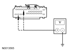
|
Yes REPAIR the affected circuit. REPEAT the self-test. CLEAR the DTCs. For vehicles equipped with seat side air bags, DISCONNECT the battery ground cable. DISCONNECT the restraint system diagnostic tool from driver seat side air bag module C327 and CONNECT driver seat side air bag module C327. REPOWER the SRS. REFER to Section 501-20B. No GO to J22. | |||||||||||||||||||||||||||
| J22 CHECK CIRCUITS CPS25 (WH/VT) AND CPS24 (GY) FOR AN OPEN | ||||||||||||||||||||||||||||
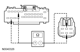
|
Yes INSTALL a new DSM. REFER to Section 419-10. CARRY OUT programmable module installation (PMI). REFER to Section 418-01. REPEAT the self-test. CLEAR the DTCs. For vehicles equipped with seat side air bags, DISCONNECT the battery ground cable. DISCONNECT the restraint system diagnostic tool from driver seat side air bag module C327 and CONNECT driver seat side air bag module C327. REPOWER the SRS. REFER to Section 501-20B. No REPAIR the affected circuit. REPEAT the self-test. CLEAR the DTCs. For vehicles equipped with seat side air bags, DISCONNECT the battery ground cable. DISCONNECT the restraint system diagnostic tool from driver seat side air bag module C327 and CONNECT driver seat side air bag module C327. REPOWER the SRS. REFER to Section 501-20B. | |||||||||||||||||||||||||||
| J23 CHECK THE REAR HEIGHT MOTOR FOR CORRECT OPERATION | ||||||||||||||||||||||||||||
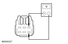
|
Yes INSTALL a new driver seat track assembly. REFER to Seat Track in this section. REPEAT the self-test. CLEAR the DTCs. For vehicles equipped with seat side air bags, DISCONNECT the battery ground cable. DISCONNECT the restraint system diagnostic tool from driver seat side air bag module C327 and CONNECT driver seat side air bag module C327. REPOWER the SRS. REFER to Section 501-20B. No GO to J24. | |||||||||||||||||||||||||||
| J24 CHECK CIRCUITS CPS27 (BU/BN) AND CPS26 (YE/BU) FOR A SHORT TO POWER | ||||||||||||||||||||||||||||
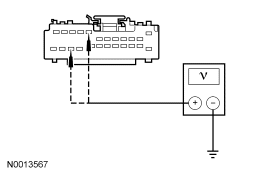
|
Yes REPAIR the affected circuit. REPEAT the self-test. CLEAR the DTCs. No GO to J25. For vehicles equipped with seat side air bags, DISCONNECT the battery ground cable. DISCONNECT the restraint system diagnostic tool from driver seat side air bag module C327 and CONNECT driver seat side air bag module C327. REPOWER the SRS. REFER to Section 501-20B. | |||||||||||||||||||||||||||
| J25 CHECK CIRCUITS CPS27 (BU/BN) AND CPS26 (YE/BU) FOR AN OPEN | ||||||||||||||||||||||||||||
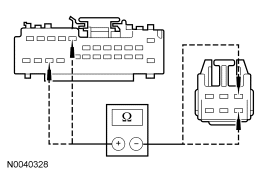
|
Yes INSTALL a new DSM. REFER to Section 419-10. CARRY OUT programmable module installation (PMI). REFER to Section 418-01. REPEAT the self-test. CLEAR the DTCs. DISCONNECT the battery ground cable. DISCONNECT the restraint system diagnostic tool from driver seat side air bag module C327 and CONNECT driver seat side air bag module C327. REPOWER the SRS. REFER to Section 501-20B. No REPAIR the affected circuit. REPEAT the self-test. CLEAR the DTCs. DISCONNECT the battery ground cable. DISCONNECT the restraint system diagnostic tool from driver seat side air bag module C327 and CONNECT driver seat side air bag module C327. REPOWER the SRS. REFER to Section 501-20B. | |||||||||||||||||||||||||||
| J26 CHECK THE HORIZONTAL MOTOR FOR CORRECT OPERATION | ||||||||||||||||||||||||||||
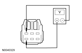
|
Yes INSTALL a new driver seat track assembly. REFER to Seat Track in this section. REPEAT the self-test. CLEAR the DTCs. For vehicles equipped with seat side air bags, DISCONNECT the battery ground cable. DISCONNECT the restraint system diagnostic tool from driver seat side air bag module C327 and CONNECT driver seat side air bag module C327. REPOWER the SRS. REFER to Section 501-20B. No GO to J27. | |||||||||||||||||||||||||||
| J27 CHECK CIRCUITS CPS22 (BN) AND CPS23 (GN/VT) FOR A SHORT TO POWER | ||||||||||||||||||||||||||||
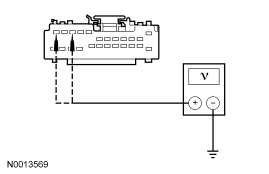
|
Yes REPAIR the affected circuit. REPEAT the self-test. CLEAR the DTCs. For vehicles equipped with seat side air bags, DISCONNECT the battery ground cable. DISCONNECT the restraint system diagnostic tool from driver seat side air bag module C327 and CONNECT driver seat side air bag module C327. REPOWER the SRS. REFER to Section 501-20B. No GO to J28. | |||||||||||||||||||||||||||
| J28 CHECK CIRCUITS CPS23 (GN/VT) AND CPS22 (BN) FOR AN OPEN | ||||||||||||||||||||||||||||
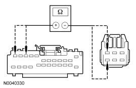
|
Yes INSTALL a new DSM. REFER to Section 419-10. CARRY OUT programmable module installation (PMI). REFER to Section 418-01. REPEAT the self-test. CLEAR the DTCs. For vehicles equipped with seat side air bags, DISCONNECT the battery ground cable. DISCONNECT the restraint system diagnostic tool from driver seat side air bag module C327 and CONNECT driver seat side air bag module C327. REPOWER the SRS. REFER to Section 501-20B. No REPAIR the affected circuit. REPEAT the self-test. CLEAR the DTCs. For vehicles equipped with seat side air bags, DISCONNECT the battery ground cable. DISCONNECT the restraint system diagnostic tool from driver seat side air bag module C327 and CONNECT driver seat side air bag module C327. REPOWER the SRS. REFER to Section 501-20B. | |||||||||||||||||||||||||||
| J29 CHECK THE DRIVER SEAT POWER RECLINER MOTOR FOR CORRECT OPERATION | ||||||||||||||||||||||||||||
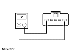
|
Yes INSTALL a new driver seat recliner motor. REFER to Seat Recliner Motor in this section. REPEAT the self-test. CLEAR the DTCs. For vehicles equipped with seat side air bags, DISCONNECT the battery ground cable. DISCONNECT the restraint system diagnostic tool from driver seat side air bag module C327 and CONNECT driver seat side air bag module C327. REPOWER the SRS. REFER to Section 501-20B. No GO to J30. | |||||||||||||||||||||||||||
| J30 CHECK CIRCUITS CPS29 (WH/BN) AND CPS30 (VT/BN) FOR A SHORT TO POWER | ||||||||||||||||||||||||||||
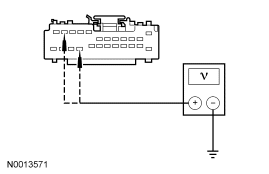
|
Yes REPAIR the affected circuit. REPEAT the self-test. CLEAR the DTCs. For vehicles equipped with seat side air bags, DISCONNECT the battery ground cable. DISCONNECT the restraint system diagnostic tool from driver seat side air bag module C327 and CONNECT driver seat side air bag module C327. REPOWER the SRS. REFER to Section 501-20B. No GO to J31. | |||||||||||||||||||||||||||
| J31 CHECK CIRCUITS CPS29 (WH/BN) AND CPS30 (VT/BN) FOR AN OPEN | ||||||||||||||||||||||||||||
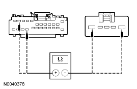
|
Yes INSTALL a new DSM. REFER to Section 419-10. CARRY OUT programmable module installation (PMI). REFER to Section 418-01. REPEAT the self-test. CLEAR the DTCs. For vehicles equipped with seat side air bags, DISCONNECT the battery ground cable. DISCONNECT the restraint system diagnostic tool from driver seat side air bag module C327 and CONNECT driver seat side air bag module C327. REPOWER the SRS. REFER to Section 501-20B. No REPAIR the affected circuit. REPEAT the self-test. CLEAR the DTCs. For vehicles equipped with seat side air bags, DISCONNECT the battery ground cable. DISCONNECT the restraint system diagnostic tool from driver seat side air bag module C327 and CONNECT driver seat side air bag module C327. REPOWER the SRS. REFER to Section 501-20B. |
Pinpoint Test K: The Memory Seat Does Not Operate Correctly — Does Not Operate Using The Memory Set Switch
Refer to Wiring Diagrams Cell 123, Memory Seats for schematic and connector information.
Normal Operation
The driver seat control switch is powered by battery voltage on circuit SBB15 (VT/RD) and is supplied ground on circuit GD126 (BK/WH). When pressed, the seat control switch supplies the voltage and ground to the applicable driver seat module (DSM) inputs. The DSM then supplies voltage and ground to the appropriate power seat track motor or power recline motor based on the inputs received from the seat control switch. When pressed in the opposite direction, the seat control switch reverses the polarity to the DSM inputs, and the DSM likewise reverses polarity of the appropriate power seat track motor or power recliner motor circuits causing the seat or backrest to move in the opposite direction. There are 3 power seat track motors that combine to move the seat horizontally (forward/rearward) and vertically (front up/down and rear up/down). The seat backrest power recliner mechanism uses a single motor to move the seat backrest forward and rearward.
Battery voltage is also supplied to DSM on circuit SBB15 (WH/RD) and SBB32 (VT/RD). Ground is supplied to the DSM on circuit GD126 (BK/WH).
Each motor, in the memory power seat track and power recliner mechanism contains a Hall-effect position sensor. The DSM supplies a signal feed circuit to each position sensor and a shared reference signal return circuit. Each position sensor sends a signal voltage back to the DSM used to monitor the position of the power seat and seat backrest. The DSM uses this information to return the seat to a stored pre-programmed position when pressing the memory SET switch or a remote entry transmitter. The memory set switch is hard-wired to the driver door module (DDM) and communicates memory SET commands to the DSM via MS-CAN. Refer to Principles of Operation in this section or the owner's literature for information on programming the DDM for storing memory seat positions.
The following pinpoint test diagnoses a memory seat that does not operate correctly using the memory set switch. If the memory seat does not move in all directions using the seat control switch, Go To Pinpoint Test J.
Possible Causes
A memory seat that does not operate correctly can be caused by:
- wiring, terminals or connectors.
- a faulty memory set switch.
- a faulty remote entry transmitter.
- a faulty memory power seat track.
- a faulty recliner mechanism.
- a faulty DSM.
PINPOINT TEST K: THE MEMORY SEAT DOES NOT OPERATE CORRECTLY — DOES NOT OPERATE USING THE MEMORY SET SWITCH
| Test Step | Result / Action to Take |
|---|---|
| K1 RETRIEVE THE DTCs | |
|
Yes If the memory SET LED fails to illuminate during the DDM On-Demand Self Test, GO to Section 501-09. If DTC B2084, GO to Section 501-09. If DTCs B1952, B1956, B1960 and B1964 are all retrieved, GO to K3 . If DTCs B1953, B1957, B1961 and B1965 are all retrieved, GO to K3 . If DTC B1530, GO to Section 501-09. If DTC B1534, GO to Section 501-09. If DTC B1538, GO to Section 501-09. If DTC B1663, GO to K4 . If DTC B1664, GO to K7 . If DTC B1665, GO to K10 . If DTC B1666, GO to K13 . If DTC B1952, GO to K7 . If DTC B1953, GO to K7 . If DTC B1956, GO to K4 . If DTC B1957, GO to K4 . If DTC B1960, GO to K13 . If DTC B1961, GO to K13 . If DTC B1964, GO to K10 . If DTC B1965, GO to K10 . If DTC B1342, INSTALL a new DSM. REFER to Section 419-10. CARRY OUT programmable module installation (PMI). REFER to Section 418-01. REPEAT the self-test. CLEAR the DTCs. For vehicles equipped with seat side air bags, DISCONNECT the battery ground cable. DISCONNECT the restraint system diagnostic tool from driver seat side air bag module C327 and CONNECT driver seat side air bag module C327. REPOWER the SRS. REFER to Section 501-20B. No GO to K2. |
| K2 MONITOR THE DDM PIDs AND CHECK THE DDM FOR CORRECT MEMORY SET SWITCH INPUTS | |
|
Yes GO to K3. No GO to Section 501-09. |
| K3 MONITOR THE DSM PIDs | |
|
Yes INSTALL a new DSM. REFER to Section 419-10. CARRY OUT programmable module installation (PMI). REFER to Section 418-01. REPEAT the self-test. CLEAR the DTCs. For vehicles equipped with seat side air bags, DISCONNECT the battery ground cable. DISCONNECT the restraint system diagnostic tool from driver seat side air bag module C327 and CONNECT driver seat side air bag module C327. REPOWER the SRS. REFER to Section 501-20B. No If the PID indicates driver seat front vertical position sensor is not present, GO to K4 . If the PID indicates driver seat rear vertical position sensor is not present, GO to K7 . If the PID indicates driver seat horizontal position sensor is not present, GO to K10 . If the PID indicates driver seat recline position sensor is not present, GO to K13 . |
| K4 CHECK CIRCUITS VPS10 (BU/GN) AND RPS13 (GN/OG) FOR A SHORT TO POWER | |
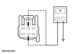
|
Yes REPAIR the affected circuit. REPEAT the self-test. CLEAR the DTCs. For vehicles equipped with seat side air bags, DISCONNECT the battery ground cable. DISCONNECT the restraint system diagnostic tool from driver seat side air bag module C327 and CONNECT driver seat side air bag module C327. REPOWER the SRS. REFER to Section 501-20B. No GO to K5. |
| K5 CHECK CIRCUITS VPS10 (BU/GN) AND RPS13 (GN/OG) FOR A SHORT TO GROUND | |
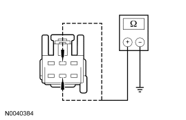
|
Yes GO to K6. No REPAIR the affected circuit. REPEAT the self-test. CLEAR the DTCs. For vehicles equipped with seat side air bags, DISCONNECT the battery ground cable. DISCONNECT the restraint system diagnostic tool from driver seat side air bag module C327 and CONNECT driver seat side air bag module C327. REPOWER the SRS. REFER to Section 501-20B. |
| K6 CHECK CIRCUITS VPS10 (BU/GN) AND RPS13 (GN/OG) FOR AN OPEN | |
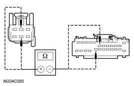
|
Yes INSTALL a new driver seat track assembly. REFER to Seat Track in this section. REPEAT the self-test. CLEAR the DTCs. For vehicles equipped with seat side air bags, DISCONNECT the battery ground cable. DISCONNECT the restraint system diagnostic tool from driver seat side air bag module C327 and CONNECT driver seat side air bag module C327. REPOWER the SRS. REFER to Section 501-20B. No REPAIR the affected circuit. REPEAT the self-test. CLEAR the DTCs. For vehicles equipped with seat side air bags, DISCONNECT the battery ground cable. DISCONNECT the restraint system diagnostic tool from driver seat side air bag module C327 and CONNECT driver seat side air bag module C327. REPOWER the SRS. REFER to Section 501-20B. |
| K7 CHECK CIRCUITS VPS11 (GN/BN) AND RPS13 (GN/OG) FOR A SHORT TO POWER | |
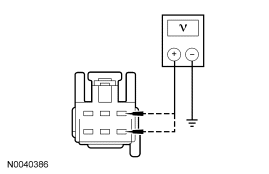
|
Yes REPAIR the affected circuit. REPEAT the self-test. CLEAR the DTCs. For vehicles equipped with seat side air bags, DISCONNECT the battery ground cable. DISCONNECT the restraint system diagnostic tool from driver seat side air bag module C327 and CONNECT driver seat side air bag module C327. REPOWER the SRS. REFER to Section 501-20B. No GO to K8. |
| K8 CHECK CIRCUITS VPS11 (GN/BN) AND RPS13 (GN/OG) FOR A SHORT TO GROUND | |
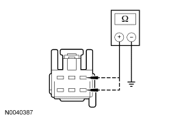
|
Yes GO to K9. No REPAIR the affected circuit. REPEAT the self-test. CLEAR the DTCs. For vehicles equipped with seat side air bags, DISCONNECT the battery ground cable. DISCONNECT the restraint system diagnostic tool from driver seat side air bag module C327 and CONNECT driver seat side air bag module C327. REPOWER the SRS. REFER to Section 501-20B. |
| K9 CHECK CIRCUITS VPS11 (GN/BN) AND RPS13 (GN/OG) AND FOR AN OPEN | |
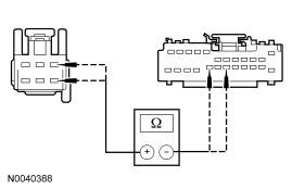
|
Yes INSTALL a new driver seat track assembly. REFER to Seat Track in this section. REPEAT the self-test. CLEAR the DTCs. For vehicles equipped with seat side air bags, DISCONNECT the battery ground cable. DISCONNECT the restraint system diagnostic tool from driver seat side air bag module C327 and CONNECT driver seat side air bag module C327. REPOWER the SRS. REFER to Section 501-20B. No REPAIR the circuit(s) in question. REPEAT the self-test. CLEAR the DTCs. For vehicles equipped with seat side air bags, DISCONNECT the battery ground cable. DISCONNECT the restraint system diagnostic tool from driver seat side air bag module C327 and CONNECT driver seat side air bag module C327. REPOWER the SRS. REFER to Section 501-20B. |
| K10 CHECK CIRCUITS VPS09 (BN/BU) AND RPS13 (GN/OG) AND FOR A SHORT TO POWER | |
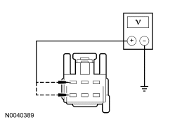
|
Yes REPAIR the affected circuit. REPEAT the self-test. CLEAR the DTCs. For vehicles equipped with seat side air bags, DISCONNECT the battery ground cable. DISCONNECT the restraint system diagnostic tool from driver seat side air bag module C327 and CONNECT driver seat side air bag module C327. REPOWER the SRS. REFER to Section 501-20B. No GO to K11. |
| K11 CHECK CIRCUITS VPS09 (BN/BU) AND RPS13 (GN/OG) FOR A SHORT TO GROUND | |
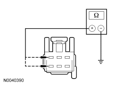
|
Yes GO to K12. No REPAIR the affected circuit. REPEAT the self-test. CLEAR the DTCs. For vehicles equipped with seat side air bags, DISCONNECT the battery ground cable. DISCONNECT the restraint system diagnostic tool from driver seat side air bag module C327 and CONNECT driver seat side air bag module C327. REPOWER the SRS. REFER to Section 501-20B. |
| K12 CHECK CIRCUITS VPS09 (BN/BU) AND RPS13 (GN/OG) FOR AN OPEN | |
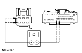
|
Yes INSTALL a new driver seat track assembly. REFER to Seat Track in this section. REPEAT the self-test. CLEAR the DTCs. For vehicles equipped with seat side air bags, DISCONNECT the battery ground cable. DISCONNECT the restraint system diagnostic tool from driver seat side air bag module C327 and CONNECT driver seat side air bag module C327. REPOWER the SRS. REFER to Section 501-20B. No REPAIR the affected circuit. REPEAT the self-test. CLEAR the DTCs. For vehicles equipped with seat side air bags, DISCONNECT the battery ground cable. DISCONNECT the restraint system diagnostic tool from driver seat side air bag module C327 and CONNECT driver seat side air bag module C327. REPOWER the SRS. REFER to Section 501-20B. |
| K13 CHECK CIRCUITS RPS13 (GN/OG) AND LPS12 (VT/RD) FOR A SHORT TO POWER | |
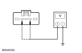
|
Yes REPAIR the affected circuit. REPEAT the self-test. CLEAR the DTCs. For vehicles equipped with seat side air bags, DISCONNECT the battery ground cable. DISCONNECT the restraint system diagnostic tool from driver seat side air bag module C327 and CONNECT driver seat side air bag module C327. REPOWER the SRS. REFER to Section 501-20B. No GO to K14. |
| K14 CHECK CIRCUITS RPS13 (GN/OG) AND LPS12 (VT/RD) FOR A SHORT TO GROUND | |
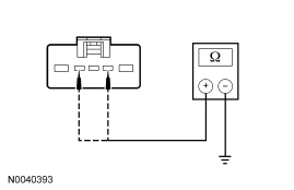
|
Yes GO to K15. No REPAIR the affected circuit. REPEAT the self-test. CLEAR the DTCs. For vehicles equipped with seat side air bags, DISCONNECT the battery ground cable. DISCONNECT the restraint system diagnostic tool from driver seat side air bag module C327 and CONNECT driver seat side air bag module C327. REPOWER the SRS. REFER to Section 501-20B. |
| K15 CHECK CIRCUITS RPS13 (GN/OG) AND LPS12 (VT/RD) FOR AN OPEN | |
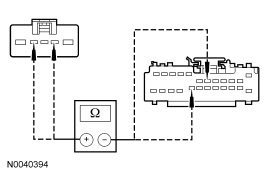
|
Yes INSTALL a new driver seat recliner motor. REFER to Seat Recliner Motor in this section. REPEAT the self-test. CLEAR the DTCs. For vehicles equipped with seat side air bags, DISCONNECT the battery ground cable. DISCONNECT the restraint system diagnostic tool from driver seat side air bag module C327 and CONNECT driver seat side air bag module C327. REPOWER the SRS. REFER to Section 501-20B. No REPAIR the affected circuit. REPEAT the self-test. CLEAR the DTCs. For vehicles equipped with seat side air bags, DISCONNECT the battery ground cable. DISCONNECT the restraint system diagnostic tool from driver seat side air bag module C327 and CONNECT driver seat side air bag module C327. REPOWER the SRS. REFER to Section 501-20B. |
Pinpoint Test L: Easy Exit/Easy Entry Is Inoperative/Does Not Operate Correctly
Normal Operation
The DSM receives a key out command over the MS-CAN communication network and powers the driver seat rearward about 2 inches.
Possible Causes
An inoperative/not operating correctly easy exit/easy entry seat can be caused by:
- wiring, terminals or connectors.
- a faulty key-in-ignition warning switch.
- a faulty instrument cluster module (ICM).
- a faulty driver seat module (DSM).
PINPOINT TEST L: EASY EXIT/EASY ENTRY IS INOPERATIVE/DOES NOT OPERATE CORRECTLY
| Test Step | Result / Action to Take |
|---|---|
| L1 CHECK THE DRIVER POWER SEAT OPERATION | |
|
Yes GO to L2. No REFER to the Symptom Chart for diagnosis of inoperative driver power seat horizontal movement. |
| L2 CHECK THE EASY EXIT OPERATION | |
|
Yes GO to L5. No GO to L3. |
| L3 CHECK THE INSTRUMENT CLUSTER MODULE (ICM) FOR CORRECT INPUTS | |
|
Yes GO to L4. No To diagnose the key-in-ignition warning switch fault, REFER to Section 413-09. |
| L4 CHECK FOR DTCS FROM THE DSM | |
|
Yes REFER to the Driver Seat Module (DSM) DTC Index for DSM DTC diagnosis. No INSTALL a new DSM. REFER to Section 419-10. CARRY OUT programmable module installation (PMI). REFER to Section 418-01. REPEAT the self test. CLEAR the DTCs. |
| L5 CHECK THE EASY ENTRY OPERATION | |
|
Yes The system is operating correctly at this time. RETEST the system for intermittent operation. If no fault is found, INSTRUCT the customer on the correct operation of the system. No Install a new DSM. REFER to Section 419-10. CARRY OUT programmable module installation (PMI). REFER to Section 418-01. |
Pinpoint Test M: The Power Lumbar Is Inoperative — Driver
Refer to Wiring Diagrams Cell 123, Memory Seats for schematic and connector information.
Normal Operation
The seat control switch is powered by battery voltage on circuit SBB15 (WH/RD) and is supplied ground on circuit GD126 (BK/WH). When the knob of the seat control switch is pressed, voltage and ground are supplied to the power lumbar motor. When pressing the lumbar knob in the opposite direction, the lumbar control switch reverses the polarity to the power lumbar motor, which moves the lumbar mechanism in the opposite direction.
Possible Causes
An inoperative power lumbar can be caused by:
- wiring, terminals or connectors.
- a faulty lumbar control switch.
- a faulty power lumbar motor assembly.
PINPOINT TEST M: THE POWER LUMBAR IS INOPERATIVE — DRIVER
| Test Step | Result / Action to Take |
|---|---|
| M1 CHECK CIRCUIT SBB15 (WH/RD) FOR AN OPEN | |
|
Yes GO to M2. No VERIFY battery junction box (BJB) fuse 15 (10A) is OK. If OK, REPAIR the circuit. TEST the system for normal operation. For vehicles equipped with seat side air bags, DISCONNECT the battery ground cable. DISCONNECT the restraint system diagnostic tool from driver seat side air bag module C327 and CONNECT driver seat side air bag module C327. REPOWER the SRS. REFER to Section 501-20B. |
| M2 CHECK CIRCUIT GD126 (BK/WH) FOR AN OPEN | |
|
Yes GO to M3. No REPAIR the circuit. TEST the system for normal operation. For vehicles equipped with seat side air bags, DISCONNECT the battery ground cable. DISCONNECT the restraint system diagnostic tool from driver seat side air bag module C327 and CONNECT driver seat side air bag module C327. REPOWER the SRS. REFER to Section 501-20B. |
| M3 CHECK THE LUMBAR MOTOR | |
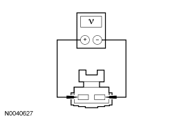
|
Yes INSTALL a new power lumbar assembly. TEST the system for normal operation. For vehicles equipped with seat side air bags, DISCONNECT the battery ground cable. DISCONNECT the restraint system diagnostic tool from driver seat side air bag module C327 and CONNECT driver seat side air bag module C327. REPOWER the SRS. REFER to Section 501-20B. No GO to M4. |
| M4 CHECK CIRCUIT CPS19 (GY/VT) AND CIRCUIT CPS18 (BN/GN) FOR A SHORT TO GROUND | |
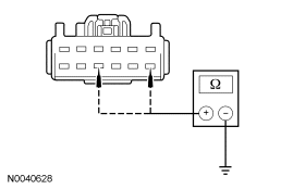
|
Yes GO to M5. No REPAIR the circuit. TEST the system for normal operation. For vehicles equipped with seat side air bags, DISCONNECT the battery ground cable. DISCONNECT the restraint system diagnostic tool from driver seat side air bag module C327 and CONNECT driver seat side air bag module C327. REPOWER the SRS. REFER to Section 501-20B. |
| M5 CHECK CIRCUIT CPS19 (GY/VT), CIRCUIT CPS18 (GN/RD) AND CPS18 (BN/GN) FOR AN OPEN | |
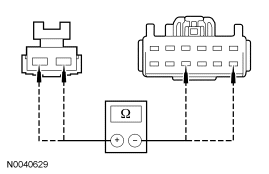
|
Yes INSTALL a new seat control switch. TEST the system for normal operation. For vehicles equipped with seat side air bags, DISCONNECT the battery ground cable. DISCONNECT the restraint system diagnostic tool from driver seat side air bag module C327 and CONNECT driver seat side air bag module C327. REPOWER the SRS. REFER to Section 501-20B. No REPAIR the circuit. TEST the system for normal operation. For vehicles equipped with seat side air bags, DISCONNECT the battery ground cable. DISCONNECT the restraint system diagnostic tool from driver seat side air bag module C327 and CONNECT driver seat side air bag module C327. REPOWER the SRS. REFER to Section 501-20B. |
Pinpoint Test N: The Power Lumbar Is Inoperative — Passenger
Refer to Wiring Diagrams Cell 120, Power Seats for schematic and connector information.
Normal Operation
The seat control switch is powered by battery voltage on circuit SBP31 (WH/RD) and is supplied ground on circuit GD139 (BK/YE). When the knob of the seat control switch is pressed, voltage and ground are supplied to the power lumbar motor. When pressing the lumbar knob in the opposite direction, the lumbar control switch reverses the polarity to the power lumbar motor, which moves the lumbar mechanism in the opposite direction.
Possible Causes
An inoperative power lumbar can be caused by:
- wiring, terminals or connectors.
- a faulty lumbar control switch.
- a faulty power lumbar motor assembly.
PINPOINT TEST N: THE POWER LUMBAR IS INOPERATIVE — PASSENGER
| Test Step | Result / Action to Take |
|---|---|
| N1 CHECK CIRCUIT SBB31 (WH/RD) FOR AN OPEN | |
|
Yes GO to N2. No VERIFY battery junction box (BJB) fuse 31 (30A) is OK. If OK, REPAIR the circuit. TEST the system for normal operation. For vehicles equipped with seat side air bags, DISCONNECT the battery ground cable. DISCONNECT the restraint system diagnostic tool from passenger seat side air bag module C313 and CONNECT passenger seat side air bag module C313. REPOWER the SRS. REFER to Section 501-20B. |
| N2 CHECK CIRCUIT GD139 (BK/YE) FOR AN OPEN | |
|
Yes GO to N3. No REPAIR the circuit. TEST the system for normal operation. For vehicles equipped with seat side air bags, DISCONNECT the battery ground cable. DISCONNECT the restraint system diagnostic tool from passenger seat side air bag module C313 and CONNECT passenger seat side air bag module C313. REPOWER the SRS. REFER to Section 501-20B. |
| N3 CHECK THE LUMBAR MOTOR | |
|
Yes INSTALL a new power lumbar assembly. TEST the system for normal operation. For vehicles equipped with seat side air bags, DISCONNECT the battery ground cable. DISCONNECT the restraint system diagnostic tool from passenger seat side air bag module C313 and CONNECT passenger seat side air bag module C313. REPOWER the SRS. REFER to Section 501-20B. No GO to N4. |
| N4 CHECK CIRCUIT CPS20 (VT) AND CIRCUIT CPS21 (YE/BK) FOR A SHORT TO GROUND | |
|
Yes GO to N5. No REPAIR the circuit. TEST the system for normal operation. For vehicles equipped with seat side air bags, DISCONNECT the battery ground cable. DISCONNECT the restraint system diagnostic tool from passenger seat side air bag module C313 and CONNECT passenger seat side air bag module C313. REPOWER the SRS. REFER to Section 501-20B. |
| N5 CHECK CIRCUIT CPS20 (VT), CIRCUIT CPS20 (WH/OG) AND CIRCUIT CPS21 (YE/BK) FOR AN OPEN | |
|
Yes INSTALL a new seat control switch. TEST the system for normal operation. For vehicles equipped with seat side air bags, DISCONNECT the battery ground cable. DISCONNECT the restraint system diagnostic tool from passenger seat side air bag module C313 and CONNECT passenger seat side air bag module C313. REPOWER the SRS. REFER to Section 501-20B. No REPAIR the circuit. TEST the system for normal operation. For vehicles equipped with seat side air bags, DISCONNECT the battery ground cable. DISCONNECT the restraint system diagnostic tool from passenger seat side air bag module C313 and CONNECT passenger seat side air bag module C313. REPOWER the SRS. REFER to Section 501-20B. |
Pinpoint Test O: The Heated Seat Is Inoperative — Driver
Refer to Wiring Diagrams Cell 119, Climate Controlled Seats for schematic and connector information.
Normal Operation
The heated seat module receives ignition voltage feed on circuit CBP19 (BN/WH), battery voltage feed on circuit SBB11 (BU/RD) and is supplied ground on circuit GD139 (BK/YE). When ignition switched power is supplied and the driver heated seat button on the electronic automatic temperature control (EATC) module is pressed, a momentary ground signal is sent to the heated seat module on circuit CHS29 (WH/BU) to command the system ON or OFF. Upon receiving a signal, the heated seat module will decrease one setting (the sequence is HI, LO, OFF, HI, etc.). The heated seat module supplies voltage to the cushion and backrest heater mats on circuit CHS02 (YE/BU). Ground to the heater mats is provided on circuit GD126 (BK/WH). The cushion and backrest heater mats are connected in series and operate together. Temperature is maintained by the heated seat module using a sensor contained within the cushion heater mat. The heated seat module supplies a reference voltage to the temperature sensor on circuit RHS05 (YE/VT) and monitors the signal from the temperature sensor on circuit VHS26 (VT) for controlling current flow to the heater mats. The heated seat module is designed to remain ON, heating the seat and maintaining temperature until switched OFF or a 15-minute time-out period occurs.
Possible Causes
An inoperative driver heated seat can be caused by:
- an open fuse.
- faulty wiring, terminals or connectors.
- a faulty heater mat.
- a faulty heated seat module.
- a faulty EATC module.
PINPOINT TEST O: THE HEATED SEAT IS INOPERATIVE — DRIVER
| Test Step | Result / Action to Take |
|---|---|
| O1 CHECK CIRCUIT SBB11 (BU/RD) FOR VOLTAGE TO THE HEATED SEAT MODULE | |
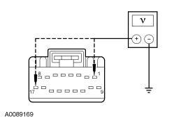
|
Yes GO to O2. No VERIFY battery junction box (BJB) fuse 11 (20A Fusion and Milan) (30A MKZ) is OK. If OK, REPAIR the circuit. TEST the system for normal operation. For vehicles equipped with seat side air bags, DISCONNECT the battery ground cable. DISCONNECT the restraint system diagnostic tool from driver seat side air bag module C327 and CONNECT driver seat side air bag module C327. DISCONNECT the restraint system diagnostic tool from passenger seat side air bag module C313 and CONNECT passenger seat side air bag module C313. REPOWER the SRS. REFER to Section 501-20B. |
| O2 CHECK CIRCUIT CBP19 (BN/WH) FOR VOLTAGE TO THE HEATED SEAT MODULE | |
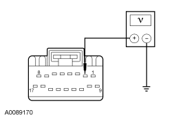
|
Yes GO to O3. No VERIFY smart junction box (SJB) fuse 28 (10A) is OK. If OK, REPAIR the circuit. TEST the system for normal operation. For vehicles equipped with seat side air bags, DISCONNECT the battery ground cable. DISCONNECT the restraint system diagnostic tool from driver seat side air bag module C327 and CONNECT driver seat side air bag module C327. DISCONNECT the restraint system diagnostic tool from passenger seat side air bag module C313 and CONNECT passenger seat side air bag module C313. REPOWER the SRS. REFER to Section 501-20B. |
| O3 CHECK HEATED SEAT MODULE GROUND CIRCUIT GD139 (BK/YE) | |
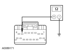
|
Yes GO to O4. No REPAIR circuit GD139 (BK/YE). TEST the system for normal operation. For vehicles equipped with seat side air bags, DISCONNECT the battery ground cable. DISCONNECT the restraint system diagnostic tool from driver seat side air bag module C327 and CONNECT driver seat side air bag module C327. DISCONNECT the restraint system diagnostic tool from passenger seat side air bag module C313 and CONNECT passenger seat side air bag module C313. REPOWER the SRS. REFER to Section 501-20B. |
| O4 CHECK CIRCUIT CHS02 (YE/BU) FOR SHORT TO VOLTAGE | |
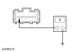
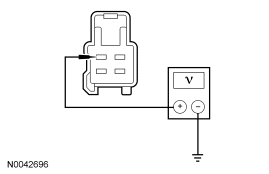
|
Yes REPAIR circuit CHS02 (YE/BU). TEST the system for normal operation. For vehicles equipped with seat side air bags, DISCONNECT the battery ground cable. DISCONNECT the restraint system diagnostic tool from driver seat side air bag module C327 and CONNECT driver seat side air bag module C327. DISCONNECT the restraint system diagnostic tool from passenger seat side air bag module C313 and CONNECT passenger seat side air bag module C313. REPOWER the SRS. REFER to Section 501-20B. No GO to O5. |
| O5 CHECK CIRCUIT CHS02 (YE/BU) FOR AN OPEN OR SHORT TO GROUND | |
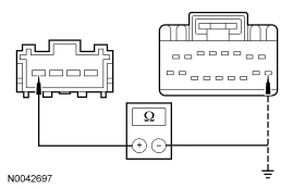
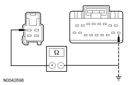
|
Yes GO to O6. No REPAIR circuit CHS02 (YE/BU). TEST the system for normal operation. For vehicles equipped with seat side air bags, DISCONNECT the battery ground cable. DISCONNECT the restraint system diagnostic tool from driver seat side air bag module C327 and CONNECT driver seat side air bag module C327. DISCONNECT the restraint system diagnostic tool from passenger seat side air bag module C313 and CONNECT passenger seat side air bag module C313. REPOWER the SRS. REFER to Section 501-20B. |
| O6 CHECK CIRCUIT CHS11 (VT/GN) FOR SHORT TO VOLTAGE | |
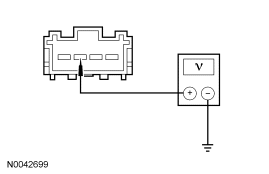
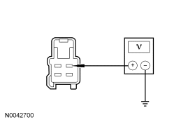
|
Yes REPAIR circuit CHS11 (VT/GN). TEST the system for normal operation. For vehicles equipped with seat side air bags, DISCONNECT the battery ground cable. DISCONNECT the restraint system diagnostic tool from driver seat side air bag module C327 and CONNECT driver seat side air bag module C327. DISCONNECT the restraint system diagnostic tool from passenger seat side air bag module C313 and CONNECT passenger seat side air bag module C313. REPOWER the SRS. REFER to Section 501-20B. No GO to O7. |
| O7 CHECK CIRCUIT CHS11 (VT/GN) FOR AN OPEN OR SHORT TO GROUND | |
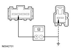
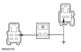
|
Yes GO to O8. No REPAIR circuit CHS11 (VT/GN). TEST the system for normal operation. For vehicles equipped with seat side air bags, DISCONNECT the battery ground cable. DISCONNECT the restraint system diagnostic tool from driver seat side air bag module C327 and CONNECT driver seat side air bag module C327. DISCONNECT the restraint system diagnostic tool from passenger seat side air bag module C313 and CONNECT passenger seat side air bag module C313. REPOWER the SRS. REFER to Section 501-20B. |
| O8 CHECK CIRCUIT GD126 (BK/WH) FOR AN OPEN | |
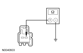
|
Yes GO to O9. No REPAIR circuit GD126 (BK/WH). TEST the system for normal operation. For vehicles equipped with seat side air bags, DISCONNECT the battery ground cable. DISCONNECT the restraint system diagnostic tool from driver seat side air bag module C327 and CONNECT driver seat side air bag module C327. DISCONNECT the restraint system diagnostic tool from passenger seat side air bag module C313 and CONNECT passenger seat side air bag module C313. REPOWER the SRS. REFER to Section 501-20B. |
| O9 CHECK CUSHION HEATER FOR SHORT TO GROUND OR AN OPEN | |
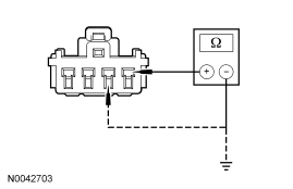
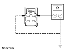
|
Yes GO to O10. No INSTALL a new driver seat cushion heater. TEST the system for normal operation. For vehicles equipped with seat side air bags, DISCONNECT the battery ground cable. DISCONNECT the restraint system diagnostic tool from driver seat side air bag module C327 and CONNECT driver seat side air bag module C327. DISCONNECT the restraint system diagnostic tool from passenger seat side air bag module C313 and CONNECT passenger seat side air bag module C313. REPOWER the SRS. REFER to Section 501-20B. |
| O10 CHECK THE SEAT BACKREST HEATER | |
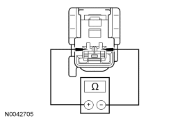
|
Yes GO to O11. No INSTALL a new driver seat backrest heater. TEST the system for normal operation. For vehicles equipped with seat side air bags, DISCONNECT the battery ground cable. DISCONNECT the restraint system diagnostic tool from driver seat side air bag module C327 and CONNECT driver seat side air bag module C327. DISCONNECT the restraint system diagnostic tool from passenger seat side air bag module C313 and CONNECT passenger seat side air bag module C313. REPOWER the SRS. REFER to Section 501-20B. |
| O11 CHECK THE HEATED SEAT TEMPERATURE SENSOR AND CIRCUITS FOR A SHORT TO VOLTAGE | |
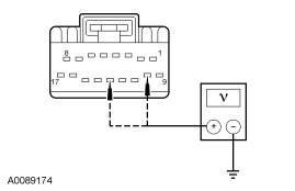
|
Yes REPAIR the affected circuit RHS05 (YE/VT) or VHS26 (VT). TEST the system for normal operation. For vehicles equipped with seat side air bags, DISCONNECT the battery ground cable. DISCONNECT the restraint system diagnostic tool from driver seat side air bag module C327 and CONNECT driver seat side air bag module C327. DISCONNECT the restraint system diagnostic tool from passenger seat side air bag module C313 and CONNECT passenger seat side air bag module C313. REPOWER the SRS. REFER to Section 501-20B. No GO to O12. |
| O12 CHECK THE HEATED SEAT TEMPERATURE SENSOR AND CIRCUITS FOR AN OPEN OR SHORT TO GROUND | |
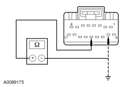
|
Yes GO to O15. No GO to O13. |
| O13 CHECK CIRCUIT RHS05 (YE/VT) FOR AN OPEN OR SHORT TO GROUND | |
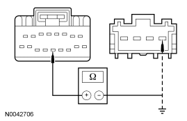
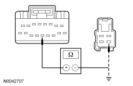
|
Yes GO to O14. No REPAIR circuit RHS05 (YE/VT). TEST the system for normal operation. For vehicles equipped with seat side air bags, DISCONNECT the battery ground cable. DISCONNECT the restraint system diagnostic tool from driver seat side air bag module C327 and CONNECT driver seat side air bag module C327. DISCONNECT the restraint system diagnostic tool from passenger seat side air bag module C313 and CONNECT passenger seat side air bag module C313. REPOWER the SRS. REFER to Section 501-20B. |
| O14 CHECK CIRCUIT VHS26 (VT) FOR AN OPEN OR SHORT TO GROUND | |
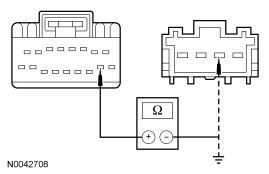
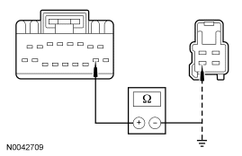
|
Yes INSTALL a new driver seat cushion heater. TEST the system for normal operation. For vehicles equipped with seat side air bags, DISCONNECT the battery ground cable. DISCONNECT the restraint system diagnostic tool from driver seat side air bag module C327 and CONNECT driver seat side air bag module C327. DISCONNECT the restraint system diagnostic tool from passenger seat side air bag module C313 and CONNECT passenger seat side air bag module C313. REPOWER the SRS. REFER to Section 501-20B. No REPAIR circuit VHS26 (VT). TEST the system for normal operation. For vehicles equipped with seat side air bags, DISCONNECT the battery ground cable. DISCONNECT the restraint system diagnostic tool from driver seat side air bag module C327 and CONNECT driver seat side air bag module C327. DISCONNECT the restraint system diagnostic tool from passenger seat side air bag module C313 and CONNECT passenger seat side air bag module C313. REPOWER the SRS. REFER to Section 501-20B. |
| O15 CHECK CIRCUIT CHS29 (WH/BU) FOR A SHORT TO VOLTAGE | |
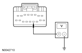
|
Yes GO to O16. No REPAIR circuit CHS29 (WH/BU). TEST the system for normal operation. For vehicles equipped with seat side air bags, DISCONNECT the battery ground cable. DISCONNECT the restraint system diagnostic tool from driver seat side air bag module C327 and CONNECT driver seat side air bag module C327. DISCONNECT the restraint system diagnostic tool from passenger seat side air bag module C313 and CONNECT passenger seat side air bag module C313. REPOWER the SRS. REFER to Section 501-20B. |
| O16 CHECK CIRCUIT CHS29 (WH/BU) FOR A SHORT TO GROUND | |
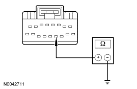
|
Yes GO to O17. No REPAIR circuit CHS29 (WH/BU). TEST the system for normal operation. For vehicles equipped with seat side air bags, DISCONNECT the battery ground cable. DISCONNECT the restraint system diagnostic tool from driver seat side air bag module C327 and CONNECT driver seat side air bag module C327. DISCONNECT the restraint system diagnostic tool from passenger seat side air bag module C313 and CONNECT passenger seat side air bag module C313. REPOWER the SRS. REFER to Section 501-20B. |
| O17 CHECK CIRCUIT CHS29 (WH/BU) FOR AN OPEN | |
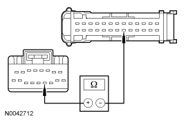
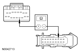
|
Yes GO to O18. No REPAIR circuit CHS29 (WH/BU). TEST the system for normal operation. For vehicles equipped with seat side air bags, DISCONNECT the battery ground cable. DISCONNECT the restraint system diagnostic tool from driver seat side air bag module C327 and CONNECT driver seat side air bag module C327. DISCONNECT the restraint system diagnostic tool from passenger seat side air bag module C313 and CONNECT passenger seat side air bag module C313. REPOWER the SRS. REFER to Section 501-20B. |
| O18 CHECK THE EATC MODULE OUTPUT | |
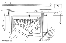
|
Yes INSTALL a new heated seat module. TEST the system for normal operation. For vehicles equipped with seat side air bags, DISCONNECT the battery ground cable. DISCONNECT the restraint system diagnostic tool from driver seat side air bag module C327 and CONNECT driver seat side air bag module C327. DISCONNECT the restraint system diagnostic tool from passenger seat side air bag module C313 and CONNECT passenger seat side air bag module C313. REPOWER the SRS. REFER to Section 501-20B. No If the voltage is greater than 10 volts but did not drop when the driver heated seat button was pressed, INSTALL a new EATC module. REFER to Section 412-01. TEST the system for normal operation. If the voltage is less than 10 volts, INSTALL a new heated seat module. TEST the system for normal operation. For vehicles equipped with seat side air bags, DISCONNECT the battery ground cable. DISCONNECT the restraint system diagnostic tool from driver seat side air bag module C327 and CONNECT driver seat side air bag module C327. DISCONNECT the restraint system diagnostic tool from passenger seat side air bag module C313 and CONNECT passenger seat side air bag module C313. REPOWER the SRS. REFER to Section 501-20B. |
Pinpoint Test P: The Heated Seat Is Inoperative — Passenger
Refer to Wiring Diagrams Cell 119, Climate Controlled Seats for schematic and connector information.
Normal Operation
The heated seat module receives ignition voltage feed on circuit CBP19 (BN/WH), battery voltage feed on circuit SBB11 (BU/RD) and is supplied ground on circuit GD139 (BK/YE). When ignition switched power is supplied and the passenger heated seat button on the electronic automatic temperature control (EATC) module is pressed, a momentary ground signal is sent to the heated seat module on circuit CHS30 (GN/YE) to command the system ON or OFF. Upon receiving a signal, the heated seat module will decrease one setting (the sequence is HI, LO, OFF, HI, etc.). The heated seat module supplies voltage to the cushion and backrest heater mats on circuit CHS07 (GY/BU). Ground to the heater mats is provided on circuit GD139 (BK/YE). The cushion and backrest heater mats are connected in series and operate together. Temperature is maintained by the heated seat module using a sensor contained within the cushion heater mat. The heated seat module supplies a reference voltage to the temperature sensor on circuit RHS05 (YE/VT) and monitors the signal from the temperature sensor on circuit VHS27 (WH/OG) for controlling current flow to the heater mats. The heated seat module is designed to remain ON, heating the seat and maintaining temperature until switched OFF or a 15-minute time-out period occurs.
Possible Causes
An inoperative passenger heated seat can be caused by:
- an open fuse.
- faulty wiring, terminals or connectors.
- a faulty heater mat.
- a faulty heated seat module.
- a faulty EATC module.
PINPOINT TEST P: THE HEATED SEAT IS INOPERATIVE — PASSENGER
| Test Step | Result / Action to Take |
|---|---|
| P1 CHECK CIRCUIT SBB11 (BU/RD) FOR VOLTAGE TO THE HEATED SEAT MODULE | |
|
Yes GO to P2. No VERIFY battery junction box (BJB) fuse 11 (20A Fusion and Milan) (30A MKZ) is OK. If OK, REPAIR the circuit. TEST the system for normal operation. For vehicles equipped with seat side air bags, DISCONNECT the battery ground cable. DISCONNECT the restraint system diagnostic tool from passenger seat side air bag module C313 and CONNECT passenger seat side air bag module C313. REPOWER the SRS. REFER to Section 501-20B. |
| P2 CHECK CIRCUIT CBP19 (BN/WH) FOR VOLTAGE TO THE HEATED SEAT MODULE | |
|
Yes GO to P3. No VERIFY smart junction box (SJB) fuse 28 (10A) is OK. If OK, REPAIR the circuit. TEST the system for normal operation. For vehicles equipped with seat side air bags, DISCONNECT the battery ground cable. DISCONNECT the restraint system diagnostic tool from passenger seat side air bag module C313 and CONNECT passenger seat side air bag module C313. REPOWER the SRS. REFER to Section 501-20B. |
| P3 CHECK HEATED SEAT MODULE GROUND CIRCUIT GD139 (BK/YE) | |
|
Yes GO to P4. No REPAIR circuit GD139 (BK/YE). TEST the system for normal operation. For vehicles equipped with seat side air bags, DISCONNECT the battery ground cable. DISCONNECT the restraint system diagnostic tool from passenger seat side air bag module C313 and CONNECT passenger seat side air bag module C313. REPOWER the SRS. REFER to Section 501-20B. |
| P4 CHECK CIRCUIT CHS07 (GY/BU) FOR SHORT TO VOLTAGE | |
|
Yes REPAIR circuit CHS07 (GY/BU). TEST the system for normal operation. For vehicles equipped with seat side air bags, DISCONNECT the battery ground cable. DISCONNECT the restraint system diagnostic tool from passenger seat side air bag module C313 and CONNECT passenger seat side air bag module C313. REPOWER the SRS. REFER to Section 501-20B. No GO to P5. |
| P5 CHECK CIRCUIT CHS07 (GY/BU) FOR AN OPEN OR SHORT TO GROUND | |
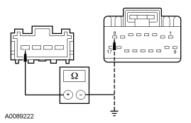
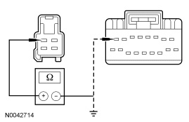
|
Yes GO to P6. No REPAIR circuit CHS07 (GY/BU). TEST the system for normal operation. For vehicles equipped with seat side air bags, DISCONNECT the battery ground cable. DISCONNECT the restraint system diagnostic tool from passenger seat side air bag module C313 and CONNECT passenger seat side air bag module C313. REPOWER the SRS. REFER to Section 501-20B. |
| P6 CHECK CIRCUIT CHS12 (YE/GN) FOR SHORT TO VOLTAGE | |
|
Yes REPAIR circuit CHS12 (YE/GN). TEST the system for normal operation. For vehicles equipped with seat side air bags, DISCONNECT the battery ground cable. DISCONNECT the restraint system diagnostic tool from passenger seat side air bag module C313 and CONNECT passenger seat side air bag module C313. REPOWER the SRS. REFER to Section 501-20B. No GO to P7. |
| P7 CHECK CIRCUIT CHS12 (YE/GN) FOR AN OPEN OR SHORT TO GROUND | |
|
Yes GO to P8. No REPAIR circuit CHS12 (YE/GN). TEST the system for normal operation. For vehicles equipped with seat side air bags, DISCONNECT the battery ground cable. DISCONNECT the restraint system diagnostic tool from passenger seat side air bag module C313 and CONNECT passenger seat side air bag module C313. REPOWER the SRS. REFER to Section 501-20B. |
| P8 CHECK CIRCUIT GD139 (BK/YE) FOR AN OPEN | |
|
Yes GO to P9. No REPAIR circuit GD139 (BK/YE). TEST the system for normal operation. For vehicles equipped with seat side air bags, DISCONNECT the battery ground cable. DISCONNECT the restraint system diagnostic tool from passenger seat side air bag module C313 and CONNECT passenger seat side air bag module C313. REPOWER the SRS. REFER to Section 501-20B. |
| P9 CHECK CUSHION HEATER FOR SHORT TO GROUND OR AN OPEN | |
|
Yes GO to P10. No INSTALL a new passenger seat cushion heater. TEST the system for normal operation. For vehicles equipped with seat side air bags, DISCONNECT the battery ground cable. DISCONNECT the restraint system diagnostic tool from passenger seat side air bag module C313 and CONNECT passenger seat side air bag module C313. REPOWER the SRS. REFER to Section 501-20B. |
| P10 CHECK THE SEAT BACKREST HEATER | |
|
Yes GO to P11. No INSTALL a new driver seat backrest heater. TEST the system for normal operation. For vehicles equipped with seat side air bags, DISCONNECT the battery ground cable. DISCONNECT the restraint system diagnostic tool from passenger seat side air bag module C313 and CONNECT passenger seat side air bag module C313. REPOWER the SRS. REFER to Section 501-20B. |
| P11 CHECK THE HEATED SEAT TEMPERATURE SENSOR AND CIRCUITS FOR A SHORT TO VOLTAGE | |
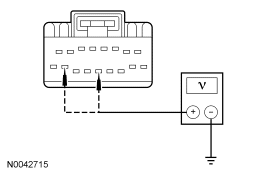
|
Yes REPAIR the affected circuit RHS05 (YE/VT) or VHS27 (WH/OG). TEST the system for normal operation. For vehicles equipped with seat side air bags, DISCONNECT the battery ground cable. DISCONNECT the restraint system diagnostic tool from passenger seat side air bag module C313 and CONNECT passenger seat side air bag module C313. REPOWER the SRS. REFER to Section 501-20B. No GO to P12. |
| P12 CHECK THE HEATED SEAT TEMPERATURE SENSOR AND CIRCUITS FOR AN OPEN OR SHORT TO GROUND | |
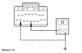
|
Yes GO to P15. No GO to P13. |
| P13 CHECK CIRCUIT RHS05 (YE/VT) FOR AN OPEN OR SHORT TO GROUND | |
|
Yes GO to P14. No REPAIR circuit RHS05 (YE/VT). TEST the system for normal operation. For vehicles equipped with seat side air bags, DISCONNECT the battery ground cable. DISCONNECT the restraint system diagnostic tool from passenger seat side air bag module C313 and CONNECT passenger seat side air bag module C313. REPOWER the SRS. REFER to Section 501-20B. |
| P14 CHECK CIRCUIT VHS27 (WH/OG) FOR AN OPEN OR SHORT TO GROUND | |
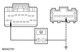
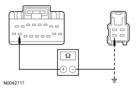
|
Yes INSTALL a new passenger seat cushion heater. TEST the system for normal operation. For vehicles equipped with seat side air bags, DISCONNECT the battery ground cable. DISCONNECT the restraint system diagnostic tool from passenger seat side air bag module C313 and CONNECT passenger seat side air bag module C313. REPOWER the SRS. REFER to Section 501-20B. No REPAIR circuit VHS27 (WH/OG). TEST the system for normal operation. For vehicles equipped with seat side air bags, DISCONNECT the battery ground cable. DISCONNECT the restraint system diagnostic tool from passenger seat side air bag module C313 and CONNECT passenger seat side air bag module C313. REPOWER the SRS. REFER to Section 501-20B. |
| P15 CHECK CIRCUIT CHS30 (GY/YE) FOR A SHORT TO VOLTAGE | |
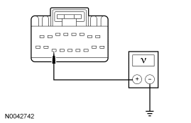
|
Yes GO to P16. No REPAIR circuit CHS30 (GY/YE). TEST the system for normal operation. For vehicles equipped with seat side air bags, DISCONNECT the battery ground cable. DISCONNECT the restraint system diagnostic tool from passenger seat side air bag module C313 and CONNECT passenger seat side air bag module C313. REPOWER the SRS. REFER to Section 501-20B. |
| P16 CHECK CIRCUIT CHS30 (GY/YE) FOR A SHORT TO GROUND | |
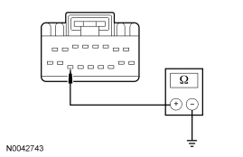
|
Yes GO to P17. No REPAIR circuit CHS30 (GY/YE). TEST the system for normal operation. For vehicles equipped with seat side air bags, DISCONNECT the battery ground cable. DISCONNECT the restraint system diagnostic tool from passenger seat side air bag module C313 and CONNECT passenger seat side air bag module C313. REPOWER the SRS. REFER to Section 501-20B. |
| P17 CHECK CIRCUIT CHS30 (GY/YE) FOR AN OPEN | |
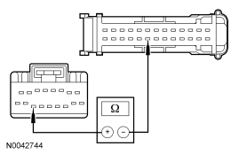
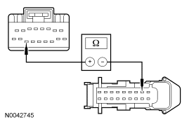
|
Yes GO to P18. No REPAIR circuit CHS30 (GY/YE). TEST the system for normal operation. For vehicles equipped with seat side air bags, DISCONNECT the battery ground cable. DISCONNECT the restraint system diagnostic tool from passenger seat side air bag module C313 and CONNECT passenger seat side air bag module C313. REPOWER the SRS. REFER to Section 501-20B. |
| P18 CHECK THE EATC MODULE OUTPUT | |
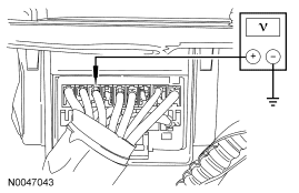
|
Yes INSTALL a new heated seat module. TEST the system for normal operation. For vehicles equipped with seat side air bags, DISCONNECT the battery ground cable. DISCONNECT the restraint system diagnostic tool from passenger seat side air bag module C313 and CONNECT passenger seat side air bag module C313. REPOWER the SRS. REFER to Section 501-20B. No If the voltage is greater than 10 volts but did not drop when the passenger heated seat button was pressed, INSTALL a new EATC module. REFER to Section 412-01. TEST the system for normal operation. For vehicles equipped with seat side air bags, DISCONNECT the battery ground cable. DISCONNECT the restraint system diagnostic tool from passenger seat side air bag module C313 and CONNECT passenger seat side air bag module C313. REPOWER the SRS. REFER to Section 501-20B. If the voltage is less than 10 volts, INSTALL a new heated seat module. TEST the system for normal operation. For vehicles equipped with seat side air bags, DISCONNECT the battery ground cable. DISCONNECT the restraint system diagnostic tool from passenger seat side air bag module C313 and CONNECT passenger seat side air bag module C313. REPOWER the SRS. REFER to Section 501-20B. |
Pinpoint Test Q: The Heated Seat Is Inoperative — Driver Seat Does Heat But The Heated Seat Indicator Does Not Illuminate When Pressed
Refer to Wiring Diagrams Cell 119, Climate Controlled Seats for schematic and connector information.
Normal Operation
Upon receiving a signal from the electronic automatic temperature control (EATC) module, the heated seat module will decrease one setting (the sequence is HI, LO, OFF, HI, etc.). When the driver heated seat is set to HI, both LED indicators above the driver heated seat control button will illuminate. When the driver heated seat is set to LO, only the left LED on the driver heated seat indicator will illuminate. When the driver heated seat is set to OFF, neither driver heated seat LED will illuminate.
Possible Causes
An inoperative heated seat indicator can be caused by:
- wiring, terminals or connectors.
- a faulty heated seat module.
- a faulty EATC module.
PINPOINT TEST Q: THE HEATED SEAT IS INOPERATIVE — DRIVER SEAT DOES HEAT BUT THE HEATED SEAT INDICATOR DOES NOT ILLUMINATE WHEN PRESSED
| Test Step | Result / Action to Take |
|---|---|
| Q1 CHECK CIRCUITS CHS04 (YE/GY) AND CHS13 (VT/BN) FOR A SHORT TO GROUND | |
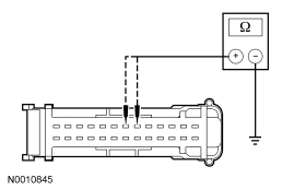
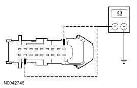
|
Yes GO to Q2. No REPAIR the affected circuit. TEST the system for normal operation. For vehicles equipped with seat side air bags, DISCONNECT the battery ground cable. DISCONNECT the restraint system diagnostic tool from driver seat side air bag module C327 and CONNECT driver seat side air bag module C327. DISCONNECT the restraint system diagnostic tool from passenger seat side air bag module C313 and CONNECT passenger seat side air bag module C313. REPOWER the SRS. REFER to Section 501-20B. |
| Q2 CHECK CIRCUITS CHS04 (YE/GY) AND CHS13 (VT/BN) FOR AN OPEN | |
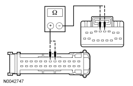
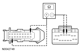
|
Yes GO to Q3. No REPAIR the affected circuit. TEST the system for normal operation. For vehicles equipped with seat side air bags, DISCONNECT the battery ground cable. DISCONNECT the restraint system diagnostic tool from driver seat side air bag module C327 and CONNECT driver seat side air bag module C327. DISCONNECT the restraint system diagnostic tool from passenger seat side air bag module C313 and CONNECT passenger seat side air bag module C313. REPOWER the SRS. REFER to Section 501-20B. |
| Q3 CHECK THE HEATED SEAT MODULE HI INDICATOR ON THE EATC MODULE | |
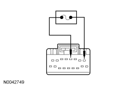
|
Yes GO to Q4. No INSTALL a new EATC module. REFER to Section 412-01. TEST the system for normal operation. For vehicles equipped with seat side air bags, DISCONNECT the battery ground cable. DISCONNECT the restraint system diagnostic tool from driver seat side air bag module C327 and CONNECT driver seat side air bag module C327. DISCONNECT the restraint system diagnostic tool from passenger seat side air bag module C313 and CONNECT passenger seat side air bag module C313. REPOWER the SRS. REFER to Section 501-20B. |
| Q4 CHECK THE HEATED SEAT MODULE LOW INDICATOR ON THE EATC MODULE | |
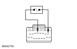
|
Yes INSTALL a new heated seat module. TEST the system for normal operation. For vehicles equipped with seat side air bags, DISCONNECT the battery ground cable. DISCONNECT the restraint system diagnostic tool from driver seat side air bag module C327 and CONNECT driver seat side air bag module C327. DISCONNECT the restraint system diagnostic tool from passenger seat side air bag module C313 and CONNECT passenger seat side air bag module C313. REPOWER the SRS. REFER to Section 501-20B. No INSTALL a new EATC module. REFER to Section 412-01. TEST the system for normal operation. For vehicles equipped with seat side air bags, DISCONNECT the battery ground cable. DISCONNECT the restraint system diagnostic tool from driver seat side air bag module C327 and CONNECT driver seat side air bag module C327. DISCONNECT the restraint system diagnostic tool from passenger seat side air bag module C313 and CONNECT passenger seat side air bag module C313. REPOWER the SRS. REFER to Section 501-20B. |
Pinpoint Test R: The Heated Seat Is Inoperative — Passenger Seat Does Heat But The Heated Seat Indicator Does Not Illuminate When Pressed
Refer to Wiring Diagrams Cell 119, Climate Controlled Seats for schematic and connector information.
Normal Operation
Upon receiving a signal from the electronic automatic temperature control (EATC) module, the heated seat module will decrease one setting (the sequence is HI, LO, OFF, HI, etc.). When the passenger heated seat is set to HI, both LED indicators above the passenger heated seat control button will illuminate. When the passenger heated seat is set to LO, only the left LED on the passenger heated seat indicator will illuminate. When the passenger heated seat is set to OFF, neither passenger heated seat LED will illuminate.
Possible Causes
An inoperative heated seat indicator can be caused by:
- wiring, terminals or connectors.
- a faulty heated seat module.
- a faulty EATC module.
PINPOINT TEST R: THE HEATED SEAT IS INOPERATIVE — PASSENGER SEAT DOES HEAT BUT THE HEATED SEAT INDICATOR DOES NOT ILLUMINATE WHEN PRESSED
| Test Step | Result / Action to Take |
|---|---|
| R1 CHECK CIRCUITS CHS09 (GY) AND CHS14 (GN) FOR A SHORT TO GROUND | |
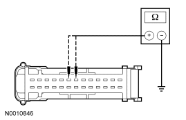
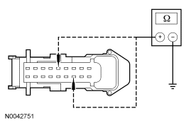
|
Yes GO to R2. No REPAIR the affected circuit. TEST the system for normal operation. For vehicles equipped with seat side air bags, DISCONNECT the battery ground cable. DISCONNECT the restraint system diagnostic tool from passenger seat side air bag module C313 and CONNECT passenger seat side air bag module C313. REPOWER the SRS. REFER to Section 501-20B. |
| R2 CHECK CIRCUITS CHS09 (GY) AND CHS14 (GN) FOR AN OPEN | |
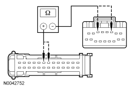
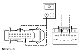
|
Yes GO to R3. No REPAIR the affected circuit. TEST the system for normal operation. For vehicles equipped with seat side air bags, DISCONNECT the battery ground cable. DISCONNECT the restraint system diagnostic tool from passenger seat side air bag module C313 and CONNECT passenger seat side air bag module C313. REPOWER the SRS. REFER to Section 501-20B. |
| R3 CHECK THE HEATED SEAT MODULE HI INDICATOR ON THE EATC MODULE | |
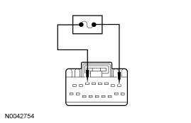
|
Yes GO to R4. No INSTALL a new EATC module. REFER to Section 412-01. TEST the system for normal operation. For vehicles equipped with seat side air bags, DISCONNECT the battery ground cable. DISCONNECT the restraint system diagnostic tool from passenger seat side air bag module C313 and CONNECT passenger seat side air bag module C313. REPOWER the SRS. REFER to Section 501-20B. |
| R4 CHECK THE HEATED SEAT MODULE LOW INDICATOR ON THE EATC MODULE | |
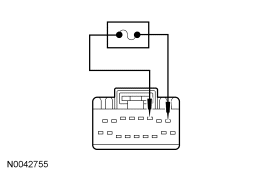
|
Yes INSTALL a new heated seat module. TEST the system for normal operation. For vehicles equipped with seat side air bags, DISCONNECT the battery ground cable. DISCONNECT the restraint system diagnostic tool from passenger seat side air bag module C313 and CONNECT passenger seat side air bag module C313. REPOWER the SRS. REFER to Section 501-20B. No INSTALL a new EATC module. REFER to Section 412-01. TEST the system for normal operation. For vehicles equipped with seat side air bags, DISCONNECT the battery ground cable. DISCONNECT the restraint system diagnostic tool from passenger seat side air bag module C313 and CONNECT passenger seat side air bag module C313. REPOWER the SRS. REFER to Section 501-20B. |
Pinpoint Test S: DTC B103B/B1111 — Thermoelectric Driver Overcurrent Low/Driver Thermoelectric Device Control Overtemperature Fault
Refer to Wiring Diagrams Cell 119, Climate Controlled Seats for schematic and connector information.
Normal Operation
Both the driver and front passenger climate controlled seats are independently controlled electronically by the dual climate controlled seat module (DCSM) mounted to the bottom of the passenger seat cushion. The climate controlled seat system only operates with the engine running, however, if using a scan tool to command the DCSM, diagnostic testing can be carried out with the ignition switch key ON engine OFF (KOEO). The system receives power from battery junction box (BJB) fuse 12 (30A) feeding battery voltage on circuit SBB12 (GN/RD) into DCSM C3305a pin F. The system also receives power from BJB fuse 11 (30A) feeding battery voltage on circuit SBB11 (BU/RD) into DCSM C3305a pin E. If power is disconnected from either pin E or F of DCSM C3305a with the power connection remaining on the other circuit, both seats will remain operational because the power feed circuits are connected internally in the DCSM. However, if a fault occurs setting a DTC specific to either climate controlled seat, only the affected seat will be disabled by the module and the other will remain operational.
Each driver and front passenger seat cushion is equipped with a thermo-electric device (TED) assembly that includes a seat blower (fan motor, serviced as an assembly with the TED). Similarly, each driver and front passenger seat backrest is also equipped with its own TED assembly with blower. Cabin air is drawn through the blower and distributed to each of the TED modules located in the seat cushion and backrest. The TEDs then heat or cool the air. The air is then directed into the foam pad and manifold where it is distributed along the surface of the cushion and backrest of the seat. Once the system is activated, the DCSM uses a set of flexible algorithms to control the heating/cooling modes and the blower speed dependant on the EATC seat switch settings.
Possible Causes
A TED driver overcurrent low or device control overtemperature fault can be caused by:
- wiring, terminals or connectors.
- a faulted TED assembly.
- a faulted DCSM.
PINPOINT TEST S: DTC B103B/B1111 — THERMOELECTRIC DRIVER OVERCURRENT LOW/DRIVER THERMOELECTRIC DEVICE CONTROL OVERTEMPERATURE FAULT
| Test Step | Result / Action to Take | ||||||||||
|---|---|---|---|---|---|---|---|---|---|---|---|
| S1 CHECK THE TED CIRCUITS FOR SHORT TO GROUND | |||||||||||
|
Yes GO to S2. No If the resistances of C3305a-G, circuit CHS02 (YE/BU) and/or C3305a-H, circuit RHS02 (BU/OG) to ground were not greater than 10,000 ohms to ground, GO to S6 . If resistances of C3305a-J, circuit CHS01 (GY/VT) and/or C3305a-K, circuit RHS01 (WH/VT) to ground were not greater than 10,000 ohms to ground, GO to S7 . | ||||||||||
| S2 CHECK THE TED CIRCUITS FOR SHORT TO VOLTAGE | |||||||||||
|
No GO to S3. No If the voltages measured at C3305a-G and/or C3305a-H were not less than 1 volt, GO to S8 . If voltages measured at C3305a-J and/or C3305a-K were not less than 1 volt, GO to S9 . | ||||||||||
| S3 CHECK THE TED RESISTANCE | |||||||||||
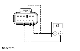
|
Yes INSTALL a new DCSM and CARRY OUT programmable module installation (PMI). REFER to Climate Controlled Seat Module. REPEAT the self-test. CLEAR the DTCs. If equipped with seat side air bags, DISCONNECT the battery ground cable. DISCONNECT the restraint system diagnostic tool from driver seat side air bag module C327 and CONNECT driver seat side air bag module C327. DISCONNECT the restraint system diagnostic tool from passenger seat side air bag module C313 and CONNECT passenger seat side air bag module C313. REPOWER the SRS. REFER to Section 501-20B. No If the resistance between DCSM C3305a-G and C3305a-H was not between 0.9 and 10 ohms, GO to S5 . If the resistance between DCSM C3305a-J and C3305a-K was not between 0.9 and 10 ohms, GO to S4 . | ||||||||||
| S4 CHECK THE RESISTANCE OF THE BACKREST TED | |||||||||||
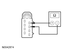
|
Yes REPAIR the affected circuit. REPEAT the self-test. CLEAR the DTCs. If equipped with seat side air bags, DISCONNECT the battery ground cable. DISCONNECT the restraint system diagnostic tool from driver seat side air bag module C327 and CONNECT driver seat side air bag module C327. DISCONNECT the restraint system diagnostic tool from passenger seat side air bag module C313 and CONNECT passenger seat side air bag module C313. REPOWER the SRS. REFER to Section 501-20B. No INSTALL a new backrest TED. REPEAT the self-test. CLEAR the DTCs. If equipped with seat side air bags, DISCONNECT the battery ground cable. DISCONNECT the restraint system diagnostic tool from driver seat side air bag module C327 and CONNECT driver seat side air bag module C327. DISCONNECT the restraint system diagnostic tool from passenger seat side air bag module C313 and CONNECT passenger seat side air bag module C313. REPOWER the SRS. REFER to Section 501-20B. | ||||||||||
| S5 CHECK THE RESISTANCE OF THE CUSHION TED | |||||||||||
|
Yes REPAIR the affected circuit. REPEAT the self-test. CLEAR the DTCs. If equipped with seat side air bags, DISCONNECT the battery ground cable. DISCONNECT the restraint system diagnostic tool from driver seat side air bag module C327 and CONNECT driver seat side air bag module C327. DISCONNECT the restraint system diagnostic tool from passenger seat side air bag module C313 and CONNECT passenger seat side air bag module C313. REPOWER the SRS. REFER to Section 501-20B. No INSTALL a new cushion TED. REPEAT the self-test. CLEAR the DTCs. If equipped with seat side air bags, DISCONNECT the battery ground cable. DISCONNECT the restraint system diagnostic tool from driver seat side air bag module C327 and CONNECT driver seat side air bag module C327. DISCONNECT the restraint system diagnostic tool from passenger seat side air bag module C313 and CONNECT passenger seat side air bag module C313. REPOWER the SRS. REFER to Section 501-20B. | ||||||||||
| S6 CHECK THE CUSHION TED CIRCUITS FOR SHORT TO GROUND | |||||||||||
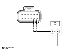
|
Yes INSTALL a new cushion TED. REPEAT the self-test. CLEAR the DTCs. If equipped with seat side air bags, DISCONNECT the battery ground cable. DISCONNECT the restraint system diagnostic tool from driver seat side air bag module C327 and CONNECT driver seat side air bag module C327. DISCONNECT the restraint system diagnostic tool from passenger seat side air bag module C313 and CONNECT passenger seat side air bag module C313. REPOWER the SRS. REFER to Section 501-20B. No REPAIR the affected circuit. REPEAT the self-test. CLEAR the DTCs. If equipped with seat side air bags, DISCONNECT the battery ground cable. DISCONNECT the restraint system diagnostic tool from driver seat side air bag module C327 and CONNECT driver seat side air bag module C327. DISCONNECT the restraint system diagnostic tool from passenger seat side air bag module C313 and CONNECT passenger seat side air bag module C313. REPOWER the SRS. REFER to Section 501-20B. | ||||||||||
| S7 CHECK THE BACKREST TED CIRCUITS FOR SHORT TO GROUND | |||||||||||
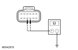
|
Yes INSTALL a new backrest TED. REPEAT the self-test. CLEAR the DTCs. If equipped with seat side air bags, DISCONNECT the battery ground cable. DISCONNECT the restraint system diagnostic tool from driver seat side air bag module C327 and CONNECT driver seat side air bag module C327. DISCONNECT the restraint system diagnostic tool from passenger seat side air bag module C313 and CONNECT passenger seat side air bag module C313. REPOWER the SRS. REFER to Section 501-20B. No REPAIR the affected circuit. REPEAT the self-test. CLEAR the DTCs. If equipped with seat side air bags, DISCONNECT the battery ground cable. DISCONNECT the restraint system diagnostic tool from driver seat side air bag module C327 and CONNECT driver seat side air bag module C327. DISCONNECT the restraint system diagnostic tool from passenger seat side air bag module C313 and CONNECT passenger seat side air bag module C313. REPOWER the SRS. REFER to Section 501-20B. | ||||||||||
| S8 CHECK THE CUSHION TED CIRCUITS FOR SHORT TO VOLTAGE | |||||||||||
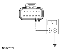
|
Yes INSTALL a new cushion TED. REPEAT the self-test. CLEAR the DTCs. If equipped with seat side air bags, DISCONNECT the battery ground cable. DISCONNECT the restraint system diagnostic tool from driver seat side air bag module C327 and CONNECT driver seat side air bag module C327. DISCONNECT the restraint system diagnostic tool from passenger seat side air bag module C313 and CONNECT passenger seat side air bag module C313. REPOWER the SRS. REFER to Section 501-20B. No REPAIR the affected circuit. REPEAT the self-test. CLEAR the DTCs. If equipped with seat side air bags, DISCONNECT the battery ground cable. DISCONNECT the restraint system diagnostic tool from driver seat side air bag module C327 and CONNECT driver seat side air bag module C327. DISCONNECT the restraint system diagnostic tool from passenger seat side air bag module C313 and CONNECT passenger seat side air bag module C313. REPOWER the SRS. REFER to Section 501-20B. | ||||||||||
| S9 CHECK THE BACKREST TED CIRCUITS FOR SHORT TO VOLTAGE | |||||||||||
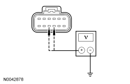
|
Yes INSTALL a new backrest TED. REPEAT the self-test. CLEAR the DTCs. If equipped with seat side air bags, DISCONNECT the battery ground cable. DISCONNECT the restraint system diagnostic tool from driver seat side air bag module C327 and CONNECT driver seat side air bag module C327. DISCONNECT the restraint system diagnostic tool from passenger seat side air bag module C313 and CONNECT passenger seat side air bag module C313. REPOWER the SRS. REFER to Section 501-20B. No REPAIR the affected circuit. REPEAT the self-test. CLEAR the DTCs. If equipped with seat side air bags, DISCONNECT the battery ground cable. DISCONNECT the restraint system diagnostic tool from driver seat side air bag module C327 and CONNECT driver seat side air bag module C327. DISCONNECT the restraint system diagnostic tool from passenger seat side air bag module C313 and CONNECT passenger seat side air bag module C313. REPOWER the SRS. REFER to Section 501-20B. |
Pinpoint Test T: DTC B103C — Thermoelectric Driver Open Load
Refer to Wiring Diagrams Cell 119, Climate Controlled Seats for schematic and connector information.
Normal Operation
Both the driver and front passenger climate controlled seats are independently controlled electronically by the dual climate controlled seat module (DCSM) mounted to the bottom of the passenger seat cushion. The climate controlled seat system only operates with the engine running, however, if using a scan tool to command the DCSM, diagnostic testing can be carried out with the ignition switch key ON engine OFF (KOEO). The system receives power from battery junction box (BJB) fuse 12 (30A) feeding battery voltage on circuit SBB12 (GN/RD) into DCSM C3305a pin F. The system also receives power from BJB fuse 11 (30A) feeding battery voltage on circuit SBB11 (BU/RD) into DCSM C3305a pin E. If power is disconnected from either pin E or F of DCSM C3305a with the power connection remaining on the other circuit, both seats will remain operational because the power feed circuits are connected internally in the DCSM. However, if a fault occurs setting a DTC specific to either climate controlled seat, only the affected seat will be disabled by the module and the other will remain operational.
Each driver and front passenger seat cushion is equipped with a thermo-electric device (TED) assembly that includes a seat blower (fan motor, serviced as an assembly with the TED). Similarly, each driver and front passenger seat backrest is also equipped with its own TED assembly with blower. Cabin air is drawn through the blower and distributed to each of the TED modules located in the seat cushion and backrest. The TEDs then heat or cool the air. The air is then directed into the foam pad and manifold where it is distributed along the surface of the cushion and backrest of the seat. Once the system is activated, the DCSM uses a set of flexible algorithms to control the heating/cooling modes and the blower speed dependant on the EATC seat switch settings.
Possible Causes
A TED driver open load fault can be caused by:
- wiring, terminals or connectors.
- a faulted TED assembly.
- a faulted DCSM.
PINPOINT TEST T: DTC B103C — THERMOELECTRIC DRIVER OPEN LOAD
| Test Step | Result / Action to Take | |||||||||||||||
|---|---|---|---|---|---|---|---|---|---|---|---|---|---|---|---|---|
| T1 CHECK THE TED CIRCUITS FOR AN OPEN | ||||||||||||||||
|
Yes GO to T2. No REPAIR the affected circuit. REPEAT the self-test. CLEAR the DTCs. If equipped with seat side air bags, DISCONNECT the battery ground cable. DISCONNECT the restraint system diagnostic tool from driver seat side air bag module C327 and CONNECT driver seat side air bag module C327. DISCONNECT the restraint system diagnostic tool from passenger seat side air bag module C313 and CONNECT passenger seat side air bag module C313. REPOWER the SRS. REFER to Section 501-20B. | |||||||||||||||
| T2 CHECK THE TED CIRCUITS FOR SHORT TO VOLTAGE | ||||||||||||||||
|
Yes REPAIR the affected circuit. REPEAT the self-test. CLEAR the DTCs. If equipped with seat side air bags, DISCONNECT the battery ground cable. DISCONNECT the restraint system diagnostic tool from driver seat side air bag module C327 and CONNECT driver seat side air bag module C327. DISCONNECT the restraint system diagnostic tool from passenger seat side air bag module C313 and CONNECT passenger seat side air bag module C313. REPOWER the SRS. REFER to Section 501-20B. No GO to T3. | |||||||||||||||
| T3 CHECK RESISTANCE OF THE TEDS | ||||||||||||||||
|
Yes INSTALL a new DCSM and CARRY OUT programmable module installation (PMI). REFER to Climate Controlled Seat Module. REPEAT the self-test. CLEAR the DTCs. If equipped with seat side air bags, DISCONNECT the battery ground cable. DISCONNECT the restraint system diagnostic tool from driver seat side air bag module C327 and CONNECT driver seat side air bag module C327. DISCONNECT the restraint system diagnostic tool from passenger seat side air bag module C313 and CONNECT passenger seat side air bag module C313. REPOWER the SRS. REFER to Section 501-20B. No If the resistance of the backrest TED was not between 0.9 and 10 ohms, INSTALL a new backrest TED. REPEAT the self-test. CLEAR the DTCs. If the resistance of the cushion TED was not between 0.9 and 10 ohms, INSTALL a new cushion TED. REPEAT the self-test. CLEAR the DTCs. If equipped with seat side air bags, DISCONNECT the battery ground cable. DISCONNECT the restraint system diagnostic tool from driver seat side air bag module C327 and CONNECT driver seat side air bag module C327. DISCONNECT the restraint system diagnostic tool from passenger seat side air bag module C313 and CONNECT passenger seat side air bag module C313. REPOWER the SRS. REFER to Section 501-20B. |
Pinpoint Test U: DTC B103D — Blower Driver Overtemperature
Refer to Wiring Diagrams Cell 119, Climate Controlled Seats for schematic and connector information.
Normal Operation
Both the driver and front passenger climate controlled seats are independently controlled electronically by the dual climate controlled seat module (DCSM) mounted to the bottom of the passenger seat cushion. The climate controlled seat system only operates with the engine running, however, if using a scan tool to command the DCSM, diagnostic testing can be carried out with the ignition switch key ON engine OFF (KOEO). The system receives power from battery junction box (BJB) fuse 12 (30A) feeding battery voltage on circuit SBB12 (GN/RD) into DCSM C3305a pin F. The system also receives power from BJB fuse 11 (30A) feeding battery voltage on circuit SBB11 (BU/RD) into DCSM C3305a pin E. If power is disconnected from either pin E or F of DCSM C3305a with the power connection remaining on the other circuit, both seats will remain operational because the power feed circuits are connected internally in the DCSM. However, if a fault occurs setting a DTC specific to either climate controlled seat, only the affected seat will be disabled by the module and the other will remain operational.
Each driver and front passenger seat cushion is equipped with a thermo-electric device (TED) assembly that includes a seat blower (fan motor, serviced as an assembly with the TED). Similarly, each driver and front passenger seat backrest is also equipped with its own TED assembly with blower. Cabin air is drawn through the blower and distributed to each of the TED modules located in the seat cushion and backrest. The TEDs then heat or cool the air. The air is then directed into the foam pad and manifold where it is distributed along the surface of the cushion and backrest of the seat. Once the system is activated, the DCSM uses a set of flexible algorithms to control the heating/cooling modes and the blower speed dependant on the EATC seat switch settings.
Possible Causes
A blower overtemperature fault can be caused by:
- wiring, terminals or connectors.
- a faulted TED assembly.
- a faulted DCSM.
PINPOINT TEST U: DTC B103D — BLOWER DRIVER OVERTEMPERATURE
| Test Step | Result / Action to Take |
|---|---|
| U1 CHECK THE BLOWER CIRCUIT FOR AN OPEN | |
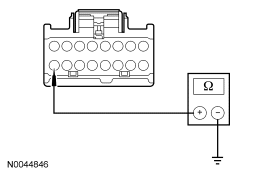
|
Yes GO to U2. No REPAIR the affected circuit. REPEAT the self-test. If equipped with seat side air bags, DISCONNECT the battery ground cable. DISCONNECT the restraint system diagnostic tool from driver seat side air bag module C327 and CONNECT driver seat side air bag module C327. DISCONNECT the restraint system diagnostic tool from passenger seat side air bag module C313 and CONNECT passenger seat side air bag module C313. REPOWER the SRS. REFER to Section 501-20B. |
| U2 CHECK THE BLOWER CIRCUITS FOR A SHORT | |
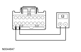
|
Yes GO to U3. No REPAIR the affected circuits. REPEAT the self-test. CLEAR the DTCs. If equipped with seat side air bags, DISCONNECT the battery ground cable. DISCONNECT the restraint system diagnostic tool from driver seat side air bag module C327 and CONNECT driver seat side air bag module C327. DISCONNECT the restraint system diagnostic tool from passenger seat side air bag module C313 and CONNECT passenger seat side air bag module C313. REPOWER the SRS. REFER to Section 501-20B. |
| U3 CHECK THE BLOWER RESISTANCE | |
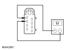
|
Yes INSTALL a new DCSM and CARRY OUT programmable module installation (PMI). REFER to Climate Controlled Seat Module. REPEAT the self-test. CLEAR the DTCs. No If the resistance of the cushion TED was not between 6,000 and 9,000 ohms, INSTALL a new cushion TED. REPEAT the self-test. CLEAR the DTCs. If the resistance of the backrest TED was not between 6,000 and 9,000 ohms, INSTALL a new backrest TED. REPEAT the self-test. CLEAR the DTCs. If equipped with seat side air bags, DISCONNECT the battery ground cable. DISCONNECT the restraint system diagnostic tool from driver seat side air bag module C327 and CONNECT driver seat side air bag module C327. DISCONNECT the restraint system diagnostic tool from passenger seat side air bag module C313 and CONNECT passenger seat side air bag module C313. REPOWER the SRS. REFER to Section 501-20B. |
Pinpoint Test V: DTC B1113/B111B — Passenger Thermoelectric Device Control Overtemperature Fault/Passenger Thermoelectric Driver Overcurrent Low
Refer to Wiring Diagrams Cell 119, Climate Controlled Seats for schematic and connector information.
Normal Operation
Both the driver and front passenger climate controlled seats are independently controlled electronically by the dual climate controlled seat module (DCSM) mounted to the bottom of the passenger seat cushion. The climate controlled seat system only operates with the engine running, however, if using a scan tool to command the DCSM, diagnostic testing can be carried out with the ignition switch key ON engine OFF (KOEO). The system receives power from battery junction box (BJB) fuse 12 (30A) feeding battery voltage on circuit SBB12 (GN/RD) into DCSM C3305a pin F. The system also receives power from BJB fuse 11 (30A) feeding battery voltage on circuit SBB11 (BU/RD) into DCSM C3305a pin E. If power is disconnected from either pin E or F of DCSM C3305a with the power connection remaining on the other circuit, both seats will remain operational because the power feed circuits are connected internally in the DCSM. However, if a fault occurs setting a DTC specific to either climate controlled seat, only the affected seat will be disabled by the module and the other will remain operational.
Each driver and front passenger seat cushion is equipped with a thermo-electric device (TED) assembly that includes a seat blower (fan motor, serviced as an assembly with the TED). Similarly, each driver and front passenger seat backrest is also equipped with its own TED assembly with blower. Cabin air is drawn through the blower and distributed to each of the TED modules located in the seat cushion and backrest. The TEDs then heat or cool the air. The air is then directed into the foam pad and manifold where it is distributed along the surface of the cushion and backrest of the seat. Once the system is activated, the DCSM uses a set of flexible algorithms to control the heating/cooling modes and the blower speed dependant on the EATC seat switch settings.
Possible Causes
A TED device control overtemperature or overcurrent low fault can be caused by:
- wiring, terminals or connectors.
- a faulted TED assembly.
- a faulted DCSM.
PINPOINT TEST V: DTC B1113/B111B — PASSENGER THERMOELECTRIC DEVICE CONTROL OVERTEMPERATURE FAULT/PASSENGER THERMOELECTRIC DRIVER OVERCURRENT LOW
| Test Step | Result / Action to Take | ||||||||||
|---|---|---|---|---|---|---|---|---|---|---|---|
| V1 CHECK THE TED CIRCUITS FOR SHORT TO GROUND | |||||||||||
|
Yes GO to V2. No If the resistances of C3305a-A and/or C3305a-B to ground were not greater than 10,000 ohms to ground, GO to V6 . If resistances of C3305a-C and/or C3305a-D to ground were not greater than 10,000 ohms to ground, GO to V7 . | ||||||||||
| V2 CHECK THE TED CIRCUITS FOR SHORT TO VOLTAGE | |||||||||||
|
Yes GO to V3. No If the voltages measured at C3305a-A and/or C3305a-B were not less than 1 volt, GO to V8 . If voltages measured at C3305a-C and/or C3305a-D were not less than 1 volt, GO to V9 . | ||||||||||
| V3 CHECK THE TED RESISTANCE | |||||||||||
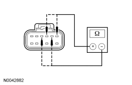
|
Yes INSTALL a new DCSM and CARRY OUT programmable module installation (PMI). REFER to Climate Controlled Seat Module. REPEAT the self-test. CLEAR the DTCs. If equipped with seat side air bags, DISCONNECT the battery ground cable. DISCONNECT the restraint system diagnostic tool from passenger seat side air bag module C313 and CONNECT passenger seat side air bag module C313. REPOWER the SRS. REFER to Section 501-20B. No If the resistance between DCSM C3305a-A and C3305a-B was not between 0.9 and 10 ohms, GO to V5 . If the resistance between DCSM C3305a-C and C3305a-D was not between 0.9 and 10 ohms, GO to V4 . | ||||||||||
| V4 CHECK THE RESISTANCE OF THE BACKREST TED | |||||||||||
|
Yes REPAIR the affected circuit. REPEAT the self-test. CLEAR the DTCs. If equipped with seat side air bags, DISCONNECT the battery ground cable. DISCONNECT the restraint system diagnostic tool from passenger seat side air bag module C313 and CONNECT passenger seat side air bag module C313. REPOWER the SRS. REFER to Section 501-20B. No INSTALL a new backrest TED. REPEAT the self-test. CLEAR the DTCs. If equipped with seat side air bags, DISCONNECT the battery ground cable. DISCONNECT the restraint system diagnostic tool from passenger seat side air bag module C313 and CONNECT passenger seat side air bag module C313. REPOWER the SRS. REFER to Section 501-20B. | ||||||||||
| V5 CHECK THE RESISTANCE OF THE CUSHION TED | |||||||||||
|
Yes REPAIR the affected circuit. REPEAT the self-test. CLEAR the DTCs. If equipped with seat side air bags, DISCONNECT the battery ground cable. DISCONNECT the restraint system diagnostic tool from passenger seat side air bag module C313 and CONNECT passenger seat side air bag module C313. REPOWER the SRS. REFER to Section 501-20B. No INSTALL a new cushion TED. REPEAT the self-test. CLEAR the DTCs. If equipped with seat side air bags, DISCONNECT the battery ground cable. DISCONNECT the restraint system diagnostic tool from passenger seat side air bag module C313 and CONNECT passenger seat side air bag module C313. REPOWER the SRS. REFER to Section 501-20B. | ||||||||||
| V6 CHECK THE CUSHION TED CIRCUITS FOR SHORT TO GROUND | |||||||||||
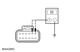
|
Yes INSTALL a new cushion TED. REPEAT the self-test. CLEAR the DTCs. If equipped with seat side air bags, DISCONNECT the battery ground cable. DISCONNECT the restraint system diagnostic tool from passenger seat side air bag module C313 and CONNECT passenger seat side air bag module C313. REPOWER the SRS. REFER to Section 501-20B. No REPAIR the affected circuit. REPEAT the self-test. CLEAR the DTCs. If equipped with seat side air bags, DISCONNECT the battery ground cable. DISCONNECT the restraint system diagnostic tool from passenger seat side air bag module C313 and CONNECT passenger seat side air bag module C313. REPOWER the SRS. REFER to Section 501-20B. | ||||||||||
| V7 CHECK THE BACKREST TED CIRCUITS FOR SHORT TO GROUND | |||||||||||
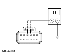
|
Yes INSTALL a new backrest TED. REPEAT the self-test. CLEAR the DTCs. If equipped with seat side air bags, DISCONNECT the battery ground cable. DISCONNECT the restraint system diagnostic tool from passenger seat side air bag module C313 and CONNECT passenger seat side air bag module C313. REPOWER the SRS. REFER to Section 501-20B. No REPAIR the affected circuit. REPEAT the self-test. CLEAR the DTCs. If equipped with seat side air bags, DISCONNECT the battery ground cable. DISCONNECT the restraint system diagnostic tool from passenger seat side air bag module C313 and CONNECT passenger seat side air bag module C313. REPOWER the SRS. REFER to Section 501-20B. | ||||||||||
| V8 CHECK THE CUSHION TED CIRCUITS FOR SHORT TO VOLTAGE | |||||||||||
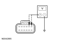
|
Yes INSTALL a new cushion TED. REPEAT the self-test. CLEAR the DTCs. If equipped with seat side air bags, DISCONNECT the battery ground cable. DISCONNECT the restraint system diagnostic tool from passenger seat side air bag module C313 and CONNECT passenger seat side air bag module C313. REPOWER the SRS. REFER to Section 501-20B. No REPAIR the affected circuit. REPEAT the self-test. CLEAR the DTCs. If equipped with seat side air bags, DISCONNECT the battery ground cable. DISCONNECT the restraint system diagnostic tool from passenger seat side air bag module C313 and CONNECT passenger seat side air bag module C313. REPOWER the SRS. REFER to Section 501-20B. | ||||||||||
| V9 CHECK THE BACKREST TED CIRCUITS FOR SHORT TO VOLTAGE | |||||||||||
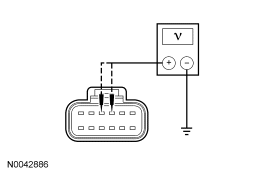
|
Yes INSTALL a new backrest TED. REPEAT the self-test. CLEAR the DTCs. If equipped with seat side air bags, DISCONNECT the battery ground cable. DISCONNECT the restraint system diagnostic tool from passenger seat side air bag module C313 and CONNECT passenger seat side air bag module C313. REPOWER the SRS. REFER to Section 501-20B. No REPAIR the affected circuit. REPEAT the self-test. CLEAR the DTCs. If equipped with seat side air bags, DISCONNECT the battery ground cable. DISCONNECT the restraint system diagnostic tool from passenger seat side air bag module C313 and CONNECT passenger seat side air bag module C313. REPOWER the SRS. REFER to Section 501-20B. |
Pinpoint Test W: DTC B111C — Passenger Thermoelectric Driver Open Load
Refer to Wiring Diagrams Cell 119, Climate Controlled Seats for schematic and connector information.
Normal Operation
Both the driver and front passenger climate controlled seats are independently controlled electronically by the dual climate controlled seat module (DCSM) mounted to the bottom of the passenger seat cushion. The climate controlled seat system only operates with the engine running, however, if using a scan tool to command the DCSM, diagnostic testing can be carried out with the ignition switch key ON engine OFF (KOEO). The system receives power from battery junction box (BJB) fuse 12 (30A) feeding battery voltage on circuit SBB12 (GN/RD) into DCSM C3305a pin F. The system also receives power from BJB fuse 11 (30A) feeding battery voltage on circuit SBB11 (BU/RD) into DCSM C3305a pin E. If power is disconnected from either pin E or F of DCSM C3305a with the power connection remaining on the other circuit, both seats will remain operational because the power feed circuits are connected internally in the DCSM. However, if a fault occurs setting a DTC specific to either climate controlled seat, only the affected seat will be disabled by the module and the other will remain operational.
Each driver and front passenger seat cushion is equipped with a thermo-electric device (TED) assembly that includes a seat blower (fan motor, serviced as an assembly with the TED). Similarly, each driver and front passenger seat backrest is also equipped with its own TED assembly with blower. Cabin air is drawn through the blower and distributed to each of the TED modules located in the seat cushion and backrest. The TEDs then heat or cool the air. The air is then directed into the foam pad and manifold where it is distributed along the surface of the cushion and backrest of the seat. Once the system is activated, the DCSM uses a set of flexible algorithms to control the heating/cooling modes and the blower speed dependant on the EATC seat switch settings.
Possible Causes
A TED driver open load fault can be caused by:
- wiring, terminals or connectors.
- a faulted TED assembly.
- a faulted DCSM.
PINPOINT TEST W: DTC B111C — PASSENGER THERMOELECTRIC DRIVER OPEN LOAD
| Test Step | Result / Action to Take | |||||||||||||||
|---|---|---|---|---|---|---|---|---|---|---|---|---|---|---|---|---|
| W1 CHECK THE TED CIRCUITS FOR AN OPEN | ||||||||||||||||
|
Yes GO to W2. No REPAIR the affected circuit. REPEAT the self-test. CLEAR the DTCs. If equipped with seat side air bags, DISCONNECT the battery ground cable. DISCONNECT the restraint system diagnostic tool from passenger seat side air bag module C313 and CONNECT passenger seat side air bag module C313. REPOWER the SRS. REFER to Section 501-20B. | |||||||||||||||
| W2 CHECK THE TED CIRCUITS FOR SHORT TO VOLTAGE | ||||||||||||||||
|
Yes REPAIR the affected circuit. REPEAT the self-test. CLEAR the DTCs. If equipped with seat side air bags, DISCONNECT the battery ground cable. DISCONNECT the restraint system diagnostic tool from passenger seat side air bag module C313 and CONNECT passenger seat side air bag module C313. REPOWER the SRS. REFER to Section 501-20B. No GO to W3. | |||||||||||||||
| W3 CHECK RESISTANCE OF THE TEDS | ||||||||||||||||
|
Yes INSTALL a new DCSM and CARRY OUT programmable module installation (PMI). REFER to Climate Controlled Seat Module. REPEAT the self-test. CLEAR the DTCs. If equipped with seat side air bags, DISCONNECT the battery ground cable. DISCONNECT the restraint system diagnostic tool from passenger seat side air bag module C313 and CONNECT passenger seat side air bag module C313. REPOWER the SRS. REFER to Section 501-20B. No If the resistance of the backrest TED was not between 0.9 and 10 ohms, INSTALL a new backrest TED. REPEAT the self-test. CLEAR the DTCs. If the resistance of the cushion TED was not between 0.9 and 10 ohms, INSTALL a new cushion TED. REPEAT the self-test. CLEAR the DTCs. If equipped with seat side air bags, DISCONNECT the battery ground cable. DISCONNECT the restraint system diagnostic tool from passenger seat side air bag module C313 and CONNECT passenger seat side air bag module C313. REPOWER the SRS. REFER to Section 501-20B. |
Pinpoint Test X: DTC B111D — Passenger Blower Driver Overtemperature
Refer to Wiring Diagrams Cell 119, Climate Controlled Seats for schematic and connector information.
Normal Operation
Both the driver and front passenger climate controlled seats are independently controlled electronically by the dual climate controlled seat module (DCSM) mounted to the bottom of the passenger seat cushion. The climate controlled seat system only operates with the engine running, however, if using a scan tool to command the DCSM, diagnostic testing can be carried out with the ignition switch key ON engine OFF (KOEO). The system receives power from battery junction box (BJB) fuse 12 (30A) feeding battery voltage on circuit SBB12 (GN/RD) into DCSM C3305a pin F. The system also receives power from BJB fuse 11 (30A) feeding battery voltage on circuit SBB11 (BU/RD) into DCSM C3305a pin E. If power is disconnected from either pin E or F of DCSM C3305a with the power connection remaining on the other circuit, both seats will remain operational because the power feed circuits are connected internally in the DCSM. However, if a fault occurs setting a DTC specific to either climate controlled seat, only the affected seat will be disabled by the module and the other will remain operational.
Each driver and front passenger seat cushion is equipped with a thermo-electric device (TED) assembly that includes a seat blower (fan motor, serviced as an assembly with the TED). Similarly, each driver and front passenger seat backrest is also equipped with its own TED assembly with blower. Cabin air is drawn through the blower and distributed to each of the TED modules located in the seat cushion and backrest. The TEDs then heat or cool the air. The air is then directed into the foam pad and manifold where it is distributed along the surface of the cushion and backrest of the seat. Once the system is activated, the DCSM uses a set of flexible algorithms to control the heating/cooling modes and the blower speed dependant on the EATC seat switch settings.
Possible Causes
A blower overtemperature fault can be caused by:
- wiring, terminals or connectors.
- a faulted TED assembly.
- a faulted DCSM.
PINPOINT TEST X: DTC B111D — PASSENGER BLOWER DRIVER OVERTEMPERATURE
| Test Step | Result / Action to Take |
|---|---|
| X1 CHECK THE BLOWER CIRCUIT FOR AN OPEN | |
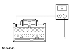
|
Yes GO to X2. No REPAIR the affected circuit. REPEAT the self-test. If equipped with seat side air bags, DISCONNECT the battery ground cable. DISCONNECT the restraint system diagnostic tool from passenger seat side air bag module C313 and CONNECT passenger seat side air bag module C313. REPOWER the SRS. REFER to Section 501-20B. |
| X2 CHECK THE BLOWER CIRCUITS FOR A SHORT | |
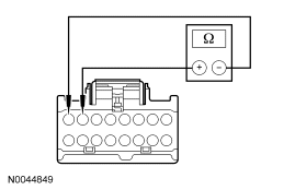
|
Yes GO to X3. No REPAIR the affected circuits. REPEAT the self-test. CLEAR the DTCs. If equipped with seat side air bags, DISCONNECT the battery ground cable. DISCONNECT the restraint system diagnostic tool from passenger seat side air bag module C313 and CONNECT passenger seat side air bag module C313. REPOWER the SRS. REFER to Section 501-20B. |
| X3 CHECK THE BLOWER RESISTANCE | |
|
Yes INSTALL a new DCSM and CARRY OUT programmable module installation (PMI). REFER to Climate Controlled Seat Module. REPEAT the self-test. CLEAR the DTCs. No If the resistance of the cushion TED was not between 6,000 and 9,000 ohms, INSTALL a new cushion TED. REPEAT the self-test. CLEAR the DTCs. If the resistance of the backrest TED was not between 6,000 and 9,000 ohms, INSTALL a new backrest TED. REPEAT the self-test. CLEAR the DTCs. If equipped with seat side air bags, DISCONNECT the battery ground cable. DISCONNECT the restraint system diagnostic tool from passenger seat side air bag module C313 and CONNECT passenger seat side air bag module C313. REPOWER the SRS. REFER to Section 501-20B. |
Pinpoint Test Y: DTC B2729 — Driver Cushion Over-Temp Detected
Refer to Wiring Diagrams Cell 119, Climate Controlled Seats for schematic and connector information.
Normal Operation
Both the driver and front passenger climate controlled seats are independently controlled electronically by the dual climate controlled seat module (DCSM) mounted to the bottom of the passenger seat cushion. The climate controlled seat system only operates with the engine running, however, if using a scan tool to command the DCSM, diagnostic testing can be carried out with the ignition switch key ON engine OFF (KOEO). The system receives power from battery junction box (BJB) fuse 12 (30A) feeding battery voltage on circuit SBB12 (GN/RD) into DCSM C3305a pin F. The system also receives power from BJB fuse 11 (30A) feeding battery voltage on circuit SBB11 (BU/RD) into DCSM C3305a pin E. If power is disconnected from either pin E or F of DCSM C3305a with the power connection remaining on the other circuit, both seats will remain operational because the power feed circuits are connected internally in the DCSM. However, if a fault occurs setting a DTC specific to either climate controlled seat, only the affected seat will be disabled by the module and the other will remain operational.
Each driver and front passenger seat cushion is equipped with a thermo-electric device (TED) assembly that includes a seat blower (fan motor, serviced as an assembly with the TED). Similarly, each driver and front passenger seat backrest is also equipped with its own TED assembly with blower. Cabin air is drawn through the blower and distributed to each of the TED modules located in the seat cushion and backrest. The TEDs then heat or cool the air. The air is then directed into the foam pad and manifold where it is distributed along the surface of the cushion and backrest of the seat. Once the system is activated, the DCSM uses a set of flexible algorithms to control the heating/cooling modes and the blower speed dependant on the EATC seat switch settings.
Possible Causes
A driver seat cushion over-temp fault can be caused by:
- wiring, terminals or connectors.
- restricted cushion TED filter.
- crushed or restricted cushion foam pad.
- crushed or restricted climate controlled seat manifold.
- a faulted cushion TED assembly.
- a faulted DCSM.
PINPOINT TEST Y: DTC B2729 — DRIVER CUSHION OVER-TEMP DETECTED
| Test Step | Result / Action to Take | ||||||||||||
|---|---|---|---|---|---|---|---|---|---|---|---|---|---|
| Y1 CHECK THE DCSM FOR ON-DEMAND DTCS | |||||||||||||
|
Yes GO to Y2. No GO to Y4. | ||||||||||||
| Y2 CHECK THE TED THERMISTOR CIRCUITS FOR A SHORT TO GROUND | |||||||||||||
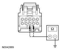
|
Yes GO to Y3. No REPAIR the affected circuit. REPEAT the self-test. CLEAR the DTCs. If equipped with seat side air bags, DISCONNECT the battery ground cable. DISCONNECT the restraint system diagnostic tool from driver seat side air bag module C327 and CONNECT driver seat side air bag module C327. DISCONNECT the restraint system diagnostic tool from passenger seat side air bag module C313 and CONNECT passenger seat side air bag module C313. REPOWER the SRS. REFER to Section 501-20B. | ||||||||||||
| Y3 CHECK THE TED THERMISTOR | |||||||||||||
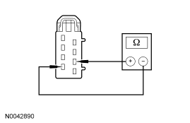
|
Yes REPAIR the affected open circuit. REPEAT the self-test. CLEAR the DTCs. If equipped with seat side air bags, DISCONNECT the battery ground cable. DISCONNECT the restraint system diagnostic tool from driver seat side air bag module C327 and CONNECT driver seat side air bag module C327. DISCONNECT the restraint system diagnostic tool from passenger seat side air bag module C313 and CONNECT passenger seat side air bag module C313. REPOWER the SRS. REFER to Section 501-20B. No INSTALL a new cushion TED. REPEAT the self-test. CLEAR the DTCs. If equipped with seat side air bags, DISCONNECT the battery ground cable. DISCONNECT the restraint system diagnostic tool from driver seat side air bag module C327 and CONNECT driver seat side air bag module C327. DISCONNECT the restraint system diagnostic tool from passenger seat side air bag module C313 and CONNECT passenger seat side air bag module C313. REPOWER the SRS. REFER to Section 501-20B. | ||||||||||||
| Y4 CONFIRM THE FAULT | |||||||||||||
|
Yes GO to Y5. No Fault not present. Fault may have been set due to a past failure or incorrect use of the climate controlled seat system by repeated switching between HEAT and COOL modes. REPEAT the self-test. CLEAR the DTCs. If equipped with seat side air bags, DISCONNECT the battery ground cable. DISCONNECT the restraint system diagnostic tool from driver seat side air bag module C327 and CONNECT driver seat side air bag module C327. DISCONNECT the restraint system diagnostic tool from passenger seat side air bag module C313 and CONNECT passenger seat side air bag module C313. REPOWER the SRS. REFER to Section 501-20B. | ||||||||||||
| Y5 CHECK OPERATION OF THE SEAT | |||||||||||||
|
Yes GO to Y14. No GO to Y6. | ||||||||||||
| Y6 CHECK THE CUSHION BLOWER FOR AN OBSTRUCTION OR RESTRICTED FILTER | |||||||||||||
|
Yes REMOVE the obstruction or INSTALL a new filter. REPEAT the self-test. CLEAR the DTCs. If equipped with seat side air bags, DISCONNECT the battery ground cable. DISCONNECT the restraint system diagnostic tool from driver seat side air bag module C327 and CONNECT driver seat side air bag module C327. DISCONNECT the restraint system diagnostic tool from passenger seat side air bag module C313 and CONNECT passenger seat side air bag module C313. REPOWER the SRS. REFER to Section 501-20B. No GO to Y7. | ||||||||||||
| Y7 CHECK THE CUSHION FAN OPERATION | |||||||||||||
|
Yes GO to Y14. No GO to Y8. | ||||||||||||
| Y8 CHECK THE BLOWER SPEED CONTROL CIRCUIT FOR AN OPEN | |||||||||||||
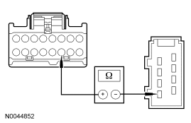
|
Yes GO to Y9. No REPAIR the circuit. REPEAT the self-test. CLEAR the DTCs. If equipped with seat side air bags, DISCONNECT the battery ground cable. DISCONNECT the restraint system diagnostic tool from driver seat side air bag module C327 and CONNECT driver seat side air bag module C327. DISCONNECT the restraint system diagnostic tool from passenger seat side air bag module C313 and CONNECT passenger seat side air bag module C313. REPOWER the SRS. REFER to Section 501-20B. | ||||||||||||
| Y9 CHECK THE BLOWER- CIRCUIT FOR A SHORT TO VOLTAGE | |||||||||||||
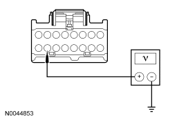
|
Yes REPAIR the circuit. REPEAT the self-test. CLEAR the DTCs. If equipped with seat side air bags, DISCONNECT the battery ground cable. DISCONNECT the restraint system diagnostic tool from driver seat side air bag module C327 and CONNECT driver seat side air bag module C327. DISCONNECT the restraint system diagnostic tool from passenger seat side air bag module C313 and CONNECT passenger seat side air bag module C313. REPOWER the SRS. REFER to Section 501-20B. No GO to Y10. | ||||||||||||
| Y10 CHECK THE BLOWER+ CIRCUIT FOR A SHORT TO GROUND | |||||||||||||
|
Yes GO to Y11. No REPAIR the circuit. REPEAT the self-test. CLEAR the DTCs. If equipped with seat side air bags, DISCONNECT the battery ground cable. DISCONNECT the restraint system diagnostic tool from driver seat side air bag module C327 and CONNECT driver seat side air bag module C327. DISCONNECT the restraint system diagnostic tool from passenger seat side air bag module C313 and CONNECT passenger seat side air bag module C313. REPOWER the SRS. REFER to Section 501-20B. | ||||||||||||
| Y11 CHECK THE BLOWER+ AND BLOWER- CIRCUITS FOR AN OPEN | |||||||||||||
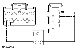
|
Yes GO to Y12. No REPAIR the affected circuit. REPEAT the self-test. CLEAR the DTCs. If equipped with seat side air bags, DISCONNECT the battery ground cable. DISCONNECT the restraint system diagnostic tool from driver seat side air bag module C327 and CONNECT driver seat side air bag module C327. DISCONNECT the restraint system diagnostic tool from passenger seat side air bag module C313 and CONNECT passenger seat side air bag module C313. REPOWER the SRS. REFER to Section 501-20B. | ||||||||||||
| Y12 CHECK THE BLOWER+ TO BLOWER- RESISTANCE | |||||||||||||
|
Yes GO to Y13. No INSTALL a new cushion TED. REPEAT the self-test. CLEAR the DTCs. If equipped with seat side air bags, DISCONNECT the battery ground cable. DISCONNECT the restraint system diagnostic tool from driver seat side air bag module C327 and CONNECT driver seat side air bag module C327. DISCONNECT the restraint system diagnostic tool from passenger seat side air bag module C313 and CONNECT passenger seat side air bag module C313. REPOWER the SRS. REFER to Section 501-20B. | ||||||||||||
| Y13 CHECK THE BLOWER SPEED CONTROL RESISTANCE | |||||||||||||
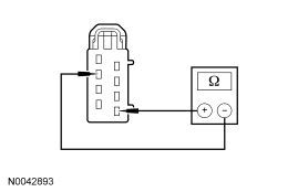
|
Yes GO to Y14. No INSTALL a new cushion TED. REPEAT the self-test. CLEAR the DTCs. If equipped with seat side air bags, DISCONNECT the battery ground cable. DISCONNECT the restraint system diagnostic tool from driver seat side air bag module C327 and CONNECT driver seat side air bag module C327. DISCONNECT the restraint system diagnostic tool from passenger seat side air bag module C313 and CONNECT passenger seat side air bag module C313. REPOWER the SRS. REFER to Section 501-20B. | ||||||||||||
| Y14 CHECK THE TED INSTALLATION AND FOR CRUSHED SEAT CUSHION | |||||||||||||
|
Yes INSTALL a new DCSM and CARRY OUT programmable module installation (PMI). REFER to Climate Controlled Seat Module. REPEAT the self-test. CLEAR the DTCs. If equipped with seat side air bags, DISCONNECT the battery ground cable. DISCONNECT the restraint system diagnostic tool from driver seat side air bag module C327 and CONNECT driver seat side air bag module C327. DISCONNECT the restraint system diagnostic tool from passenger seat side air bag module C313 and CONNECT passenger seat side air bag module C313. REPOWER the SRS. REFER to Section 501-20B. No CORRECTLY install the cushion TED or INSTALL a new seat cushion foam pad and/or climate controlled seat manifold. REPEAT the self-test. CLEAR the DTCs. If equipped with seat side air bags, DISCONNECT the battery ground cable. DISCONNECT the restraint system diagnostic tool from driver seat side air bag module C327 and CONNECT driver seat side air bag module C327. DISCONNECT the restraint system diagnostic tool from passenger seat side air bag module C313 and CONNECT passenger seat side air bag module C313. REPOWER the SRS. REFER to Section 501-20B. |
Pinpoint Test Z: DTC B272A — Passenger Cushion Over-Temp Detected
Refer to Wiring Diagrams Cell 119, Climate Controlled Seats for schematic and connector information.
Normal Operation
Both the driver and front passenger climate controlled seats are independently controlled electronically by the dual climate controlled seat module (DCSM) mounted to the bottom of the passenger seat cushion. The climate controlled seat system only operates with the engine running, however, if using a scan tool to command the DCSM, diagnostic testing can be carried out with the ignition switch key ON engine OFF (KOEO). The system receives power from battery junction box (BJB) fuse 12 (30A) feeding battery voltage on circuit SBB12 (GN/RD) into DCSM C3305a pin F. The system also receives power from BJB fuse 11 (30A) feeding battery voltage on circuit SBB11 (BU/RD) into DCSM C3305a pin E. If power is disconnected from either pin E or F of DCSM C3305a with the power connection remaining on the other circuit, both seats will remain operational because the power feed circuits are connected internally in the DCSM. However, if a fault occurs setting a DTC specific to either climate controlled seat, only the affected seat will be disabled by the module and the other will remain operational.
Each driver and front passenger seat cushion is equipped with a thermo-electric device (TED) assembly that includes a seat blower (fan motor, serviced as an assembly with the TED). Similarly, each driver and front passenger seat backrest is also equipped with its own TED assembly with blower. Cabin air is drawn through the blower and distributed to each of the TED modules located in the seat cushion and backrest. The TEDs then heat or cool the air. The air is then directed into the foam pad and manifold where it is distributed along the surface of the cushion and backrest of the seat. Once the system is activated, the DCSM uses a set of flexible algorithms to control the heating/cooling modes and the blower speed dependant on the EATC seat switch settings.
Possible Causes
A passenger seat cushion over-temp fault can be caused by:
- wiring, terminals or connectors.
- restricted cushion TED filter.
- crushed or restricted cushion foam pad.
- crushed or restricted climate controlled seat manifold.
- a faulted cushion TED assembly.
- a faulted DCSM.
PINPOINT TEST Z: DTC B272A — PASSENGER CUSHION OVER-TEMP DETECTED
| Test Step | Result / Action to Take | ||||||||||||
|---|---|---|---|---|---|---|---|---|---|---|---|---|---|
| Z1 CHECK THE DCSM FOR ON-DEMAND DTCS | |||||||||||||
|
Yes GO to Z2. No GO to Z4. | ||||||||||||
| Z2 CHECK THE TED THERMISTOR CIRCUITS FOR A SHORT TO GROUND | |||||||||||||
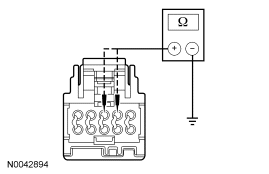
|
Yes GO to Z3. No REPAIR the affected circuit. REPEAT the self-test. CLEAR the DTCs. If equipped with seat side air bags, DISCONNECT the battery ground cable. DISCONNECT the restraint system diagnostic tool from passenger seat side air bag module C313 and CONNECT passenger seat side air bag module C313. REPOWER the SRS. REFER to Section 501-20B. | ||||||||||||
| Z3 CHECK THE TED THERMISTOR | |||||||||||||
|
Yes REPAIR the affected open circuit. REPEAT the self-test. CLEAR the DTCs. If equipped with seat side air bags, DISCONNECT the battery ground cable. DISCONNECT the restraint system diagnostic tool from passenger seat side air bag module C313 and CONNECT passenger seat side air bag module C313. REPOWER the SRS. REFER to Section 501-20B. No INSTALL a new cushion TED. REPEAT the self-test. CLEAR the DTCs. If equipped with seat side air bags, DISCONNECT the battery ground cable. DISCONNECT the restraint system diagnostic tool from passenger seat side air bag module C313 and CONNECT passenger seat side air bag module C313. REPOWER the SRS. REFER to Section 501-20B. | ||||||||||||
| Z4 CONFIRM THE FAULT | |||||||||||||
|
Yes GO to Z5. No Fault not present. Fault may have been set due to a past failure or incorrect use of the climate controlled seat system by repeated switching between HEAT and COOL modes. REPEAT the self-test. CLEAR the DTCs. If equipped with seat side air bags, DISCONNECT the battery ground cable. DISCONNECT the restraint system diagnostic tool from passenger seat side air bag module C313 and CONNECT passenger seat side air bag module C313. REPOWER the SRS. REFER to Section 501-20B. | ||||||||||||
| Z5 CHECK OPERATION OF THE SEAT | |||||||||||||
|
Yes GO to Z4. No GO to Z6. | ||||||||||||
| Z6 CHECK THE CUSHION BLOWER FOR AN OBSTRUCTION OR RESTRICTED FILTER | |||||||||||||
|
Yes REMOVE the obstruction or INSTALL a new filter. REPEAT the self-test. CLEAR the DTCs. If equipped with seat side air bags, DISCONNECT the battery ground cable. DISCONNECT the restraint system diagnostic tool from passenger seat side air bag module C313 and CONNECT passenger seat side air bag module C313. REPOWER the SRS. REFER to Section 501-20B. No GO to Z7. | ||||||||||||
| Z7 CHECK THE CUSHION FAN OPERATION | |||||||||||||
|
Yes GO to Z14. No GO to Z8. | ||||||||||||
| Z8 CHECK THE BLOWER SPEED CONTROL CIRCUIT FOR AN OPEN | |||||||||||||
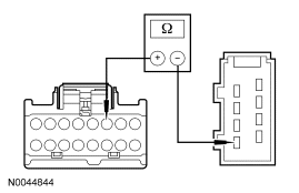
|
Yes GO to Z9. No REPAIR the circuit. REPEAT the self-test. CLEAR the DTCs. If equipped with seat side air bags, DISCONNECT the battery ground cable. DISCONNECT the restraint system diagnostic tool from passenger seat side air bag module C313 and CONNECT passenger seat side air bag module C313. REPOWER the SRS. REFER to Section 501-20B. | ||||||||||||
| Z9 CHECK THE BLOWER- CIRCUIT FOR A SHORT TO VOLTAGE | |||||||||||||
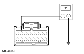
|
Yes REPAIR the circuit. REPEAT the self-test. CLEAR the DTCs. If equipped with seat side air bags, DISCONNECT the battery ground cable. DISCONNECT the restraint system diagnostic tool from passenger seat side air bag module C313 and CONNECT passenger seat side air bag module C313. REPOWER the SRS. REFER to Section 501-20B. No GO to Z10. | ||||||||||||
| Z10 CHECK THE BLOWER+ CIRCUIT FOR A SHORT TO GROUND | |||||||||||||
|
Yes GO to Z11. No REPAIR the circuit. REPEAT the self-test. CLEAR the DTCs. If equipped with seat side air bags, DISCONNECT the battery ground cable. DISCONNECT the restraint system diagnostic tool from passenger seat side air bag module C313 and CONNECT passenger seat side air bag module C313. REPOWER the SRS. REFER to Section 501-20B. | ||||||||||||
| Z11 CHECK THE BLOWER+ AND BLOWER- CIRCUITS FOR AN OPEN | |||||||||||||
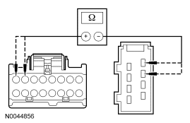
|
Yes GO to Z12. No REPAIR the affected circuit. REPEAT the self-test. CLEAR the DTCs. If equipped with seat side air bags, DISCONNECT the battery ground cable. DISCONNECT the restraint system diagnostic tool from passenger seat side air bag module C313 and CONNECT passenger seat side air bag module C313. REPOWER the SRS. REFER to Section 501-20B. | ||||||||||||
| Z12 CHECK THE BLOWER+ TO BLOWER- RESISTANCE | |||||||||||||
|
Yes GO to Z13. No INSTALL a new cushion TED. REPEAT the self-test. CLEAR the DTCs. If equipped with seat side air bags, DISCONNECT the battery ground cable. DISCONNECT the restraint system diagnostic tool from passenger seat side air bag module C313 and CONNECT passenger seat side air bag module C313. REPOWER the SRS. REFER to Section 501-20B. | ||||||||||||
| Z13 CHECK THE BLOWER SPEED CONTROL RESISTANCE | |||||||||||||
|
Yes GO to Z14. No INSTALL a new cushion TED. REPEAT the self-test. CLEAR the DTCs. If equipped with seat side air bags, DISCONNECT the battery ground cable. DISCONNECT the restraint system diagnostic tool from passenger seat side air bag module C313 and CONNECT passenger seat side air bag module C313. REPOWER the SRS. REFER to Section 501-20B. | ||||||||||||
| Z14 CHECK THE TED INSTALLATION AND FOR CRUSHED SEAT CUSHION | |||||||||||||
|
Yes INSTALL a new DCSM and CARRY OUT programmable module installation (PMI). REFER to Climate Controlled Seat Module. REPEAT the self-test. CLEAR the DTCs. If equipped with seat side air bags, DISCONNECT the battery ground cable. DISCONNECT the restraint system diagnostic tool from passenger seat side air bag module C313 and CONNECT passenger seat side air bag module C313. REPOWER the SRS. REFER to Section 501-20B. No CORRECTLY install the cushion TED or INSTALL a new seat cushion foam pad and/or climate controlled seat manifold. REPEAT the self-test. CLEAR the DTCs. If equipped with seat side air bags, DISCONNECT the battery ground cable. DISCONNECT the restraint system diagnostic tool from passenger seat side air bag module C313 and CONNECT passenger seat side air bag module C313. REPOWER the SRS. REFER to Section 501-20B. |
Pinpoint Test AA: DTC B272B — Passenger Back Over-Temp Detected
Refer to Wiring Diagrams Cell 119, Climate Controlled Seats for schematic and connector information.
Normal Operation
Both the driver and front passenger climate controlled seats are independently controlled electronically by the dual climate controlled seat module (DCSM) mounted to the bottom of the passenger seat cushion. The climate controlled seat system only operates with the engine running, however, if using a scan tool to command the DCSM, diagnostic testing can be carried out with the ignition switch key ON engine OFF (KOEO). The system receives power from battery junction box (BJB) fuse 12 (30A) feeding battery voltage on circuit SBB12 (GN/RD) into DCSM C3305a pin F. The system also receives power from BJB fuse 11 (30A) feeding battery voltage on circuit SBB11 (BU/RD) into DCSM C3305a pin E. If power is disconnected from either pin E or F of DCSM C3305a with the power connection remaining on the other circuit, both seats will remain operational because the power feed circuits are connected internally in the DCSM. However, if a fault occurs setting a DTC specific to either climate controlled seat, only the affected seat will be disabled by the module and the other will remain operational.
Each driver and front passenger seat cushion is equipped with a thermo-electric device (TED) assembly that includes a seat blower (fan motor, serviced as an assembly with the TED). Similarly, each driver and front passenger seat backrest is also equipped with its own TED assembly with blower. Cabin air is drawn through the blower and distributed to each of the TED modules located in the seat cushion and backrest. The TEDs then heat or cool the air. The air is then directed into the foam pad and manifold where it is distributed along the surface of the cushion and backrest of the seat. Once the system is activated, the DCSM uses a set of flexible algorithms to control the heating/cooling modes and the blower speed dependant on the EATC seat switch settings.
Possible Causes
A driver seat backrest over-temp fault can be caused by:
- wiring, terminals or connectors.
- restricted backrest TED filter.
- crushed or restricted backrest foam pad.
- crushed or restricted climate controlled seat manifold.
- a faulted backrest TED assembly.
- a faulted DCSM.
PINPOINT TEST AA: DTC B272B — PASSENGER BACK OVER-TEMP DETECTED
| Test Step | Result / Action to Take | ||||||||||||
|---|---|---|---|---|---|---|---|---|---|---|---|---|---|
| AA1 CHECK THE DCSM FOR ON-DEMAND DTCS | |||||||||||||
|
Yes GO to AA2. No GO to AA4. | ||||||||||||
| AA2 CHECK THE TED THERMISTOR CIRCUITS FOR A SHORT TO GROUND | |||||||||||||
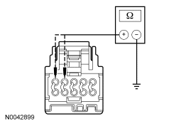
|
Yes GO to AA3. No REPAIR the affected circuit. REPEAT the self-test. CLEAR the DTCs. If equipped with seat side air bags, DISCONNECT the battery ground cable. DISCONNECT the restraint system diagnostic tool from driver seat side air bag module C327 and CONNECT driver seat side air bag module C327. DISCONNECT the restraint system diagnostic tool from passenger seat side air bag module C313 and CONNECT passenger seat side air bag module C313. REPOWER the SRS. REFER to Section 501-20B. | ||||||||||||
| AA3 CHECK THE TED THERMISTOR | |||||||||||||
|
Yes REPAIR the affected open circuit. REPEAT the self-test. CLEAR the DTCs. If equipped with seat side air bags, DISCONNECT the battery ground cable. DISCONNECT the restraint system diagnostic tool from driver seat side air bag module C327 and CONNECT driver seat side air bag module C327. DISCONNECT the restraint system diagnostic tool from passenger seat side air bag module C313 and CONNECT passenger seat side air bag module C313. REPOWER the SRS. REFER to Section 501-20B. No INSTALL a new backrest TED. REPEAT the self-test. CLEAR the DTCs. If equipped with seat side air bags, DISCONNECT the battery ground cable. DISCONNECT the restraint system diagnostic tool from driver seat side air bag module C327 and CONNECT driver seat side air bag module C327. DISCONNECT the restraint system diagnostic tool from passenger seat side air bag module C313 and CONNECT passenger seat side air bag module C313. REPOWER the SRS. REFER to Section 501-20B. | ||||||||||||
| AA4 CONFIRM THE FAULT | |||||||||||||
|
Yes GO to AA5. No Fault not present. Fault may have been set due to a past failure or incorrect use of the climate controlled seat system by repeated switching between HEAT and COOL modes. REPEAT the self-test. CLEAR the DTCs. If equipped with seat side air bags, DISCONNECT the battery ground cable. DISCONNECT the restraint system diagnostic tool from driver seat side air bag module C327 and CONNECT driver seat side air bag module C327. DISCONNECT the restraint system diagnostic tool from passenger seat side air bag module C313 and CONNECT passenger seat side air bag module C313. REPOWER the SRS. REFER to Section 501-20B. | ||||||||||||
| AA5 CHECK OPERATION OF THE SEAT | |||||||||||||
|
Yes GO to AA14. No GO to AA6. | ||||||||||||
| AA6 CHECK THE BACKREST BLOWER FOR AN OBSTRUCTION OR RESTRICTED FILTER | |||||||||||||
|
Yes REMOVE the obstruction or INSTALL a new filter. REPEAT the self-test. CLEAR the DTCs. If equipped with seat side air bags, DISCONNECT the battery ground cable. DISCONNECT the restraint system diagnostic tool from driver seat side air bag module C327 and CONNECT driver seat side air bag module C327. DISCONNECT the restraint system diagnostic tool from passenger seat side air bag module C313 and CONNECT passenger seat side air bag module C313. REPOWER the SRS. REFER to Section 501-20B. No GO to AA7. | ||||||||||||
| AA7 CHECK THE BACKREST FAN OPERATION | |||||||||||||
|
Yes GO to AA14. No GO to AA8. | ||||||||||||
| AA8 CHECK THE BLOWER SPEED CONTROL CIRCUIT FOR AN OPEN | |||||||||||||
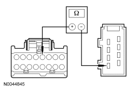
|
Yes GO to AA9. No REPAIR the circuit. REPEAT the self-test. CLEAR the DTCs. If equipped with seat side air bags, DISCONNECT the battery ground cable. DISCONNECT the restraint system diagnostic tool from driver seat side air bag module C327 and CONNECT driver seat side air bag module C327. DISCONNECT the restraint system diagnostic tool from passenger seat side air bag module C313 and CONNECT passenger seat side air bag module C313. REPOWER the SRS. REFER to Section 501-20B. | ||||||||||||
| AA9 CHECK THE BLOWER- CIRCUIT FOR A SHORT TO VOLTAGE | |||||||||||||
|
Yes REPAIR the circuit. REPEAT the self-test. CLEAR the DTCs. If equipped with seat side air bags, DISCONNECT the battery ground cable. DISCONNECT the restraint system diagnostic tool from driver seat side air bag module C327 and CONNECT driver seat side air bag module C327. DISCONNECT the restraint system diagnostic tool from passenger seat side air bag module C313 and CONNECT passenger seat side air bag module C313. REPOWER the SRS. REFER to Section 501-20B. No GO to AA10. | ||||||||||||
| AA10 CHECK THE BLOWER+ CIRCUIT FOR A SHORT TO GROUND | |||||||||||||
|
Yes GO to AA11. No REPAIR the circuit. REPEAT the self-test. CLEAR the DTCs. If equipped with seat side air bags, DISCONNECT the battery ground cable. DISCONNECT the restraint system diagnostic tool from driver seat side air bag module C327 and CONNECT driver seat side air bag module C327. DISCONNECT the restraint system diagnostic tool from passenger seat side air bag module C313 and CONNECT passenger seat side air bag module C313. REPOWER the SRS. REFER to Section 501-20B. | ||||||||||||
| AA11 CHECK THE BLOWER+ AND BLOWER- CIRCUITS FOR AN OPEN | |||||||||||||
|
Yes GO to AA12. No REPAIR the affected circuit. REPEAT the self-test. CLEAR the DTCs. If equipped with seat side air bags, DISCONNECT the battery ground cable. DISCONNECT the restraint system diagnostic tool from driver seat side air bag module C327 and CONNECT driver seat side air bag module C327. DISCONNECT the restraint system diagnostic tool from passenger seat side air bag module C313 and CONNECT passenger seat side air bag module C313. REPOWER the SRS. REFER to Section 501-20B. | ||||||||||||
| AA12 CHECK THE BLOWER+ TO BLOWER- RESISTANCE | |||||||||||||
|
Yes GO to AA13. No INSTALL a new backrest TED. REPEAT the self-test. CLEAR the DTCs. If equipped with seat side air bags, DISCONNECT the battery ground cable. DISCONNECT the restraint system diagnostic tool from driver seat side air bag module C327 and CONNECT driver seat side air bag module C327. DISCONNECT the restraint system diagnostic tool from passenger seat side air bag module C313 and CONNECT passenger seat side air bag module C313. REPOWER the SRS. REFER to Section 501-20B. | ||||||||||||
| AA13 CHECK THE BLOWER SPEED CONTROL RESISTANCE | |||||||||||||
|
Yes GO to AA14. No INSTALL a new backrest TED. REPEAT the self-test. CLEAR the DTCs. If equipped with seat side air bags, DISCONNECT the battery ground cable. DISCONNECT the restraint system diagnostic tool from driver seat side air bag module C327 and CONNECT driver seat side air bag module C327. DISCONNECT the restraint system diagnostic tool from passenger seat side air bag module C313 and CONNECT passenger seat side air bag module C313. REPOWER the SRS. REFER to Section 501-20B. | ||||||||||||
| AA14 CHECK THE TED INSTALLATION AND FOR CRUSHED SEAT BACKREST | |||||||||||||
|
Yes INSTALL a new DCSM and CARRY OUT programmable module installation (PMI). REFER to Climate Controlled Seat Module. REPEAT the self-test. CLEAR the DTCs. If equipped with seat side air bags, DISCONNECT the battery ground cable. DISCONNECT the restraint system diagnostic tool from driver seat side air bag module C327 and CONNECT driver seat side air bag module C327. DISCONNECT the restraint system diagnostic tool from passenger seat side air bag module C313 and CONNECT passenger seat side air bag module C313. REPOWER the SRS. REFER to Section 501-20B. No CORRECTLY install the backrest TED or INSTALL a new seat backrest foam pad and/or climate controlled seat manifold. REPEAT the self-test. CLEAR the DTCs. If equipped with seat side air bags, DISCONNECT the battery ground cable. DISCONNECT the restraint system diagnostic tool from driver seat side air bag module C327 and CONNECT driver seat side air bag module C327. DISCONNECT the restraint system diagnostic tool from passenger seat side air bag module C313 and CONNECT passenger seat side air bag module C313. REPOWER the SRS. REFER to Section 501-20B. |
Pinpoint Test AB: DTC B272C — Driver Differential Temperature Fault
Refer to Wiring Diagrams Cell 119, Climate Controlled Seats for schematic and connector information.
Normal Operation
Both the driver and front passenger climate controlled seats are independently controlled electronically by the dual climate controlled seat module (DCSM) mounted to the bottom of the passenger seat cushion. The climate controlled seat system only operates with the engine running, however, if using a scan tool to command the DCSM, diagnostic testing can be carried out with the ignition switch key ON engine OFF (KOEO). The system receives power from battery junction box (BJB) fuse 12 (30A) feeding battery voltage on circuit SBB12 (GN/RD) into DCSM C3305a pin F. The system also receives power from BJB fuse 11 (30A) feeding battery voltage on circuit SBB11 (BU/RD) into DCSM C3305a pin E. If power is disconnected from either pin E or F of DCSM C3305a with the power connection remaining on the other circuit, both seats will remain operational because the power feed circuits are connected internally in the DCSM. However, if a fault occurs setting a DTC specific to either climate controlled seat, only the affected seat will be disabled by the module and the other will remain operational.
Each driver and front passenger seat cushion is equipped with a thermo-electric device (TED) assembly that includes a seat blower (fan motor, serviced as an assembly with the TED). Similarly, each driver and front passenger seat backrest is also equipped with its own TED assembly with blower. Cabin air is drawn through the blower and distributed to each of the TED modules located in the seat cushion and backrest. The TEDs then heat or cool the air. The air is then directed into the foam pad and manifold where it is distributed along the surface of the cushion and backrest of the seat. Once the system is activated, the DCSM uses a set of flexible algorithms to control the heating/cooling modes and the blower speed dependant on the EATC seat switch settings.
A differential fault occurs when the cushion and backrest TEDs on an affected seat are reporting very different temperatures to the DCSM. This may result from an airflow restriction or a circuit fault of either TED area. If a TED and manifold is clear of obstruction and is operational, the other TED and circuitry on the seat should be checked. It is important to note that a TED with a higher temperature may be operating correctly and not the area of concern. The other TED may be indicating a much lower temperature, causing the DTC to set.
Possible Causes
A driver differential temperature fault can be caused by:
- wiring, terminals or connectors.
- restricted cushion or backrest TED filter.
- crushed or restricted cushion or backrest foam pad.
- crushed or restricted cushion or backrest climate controlled seat manifold.
- a faulted cushion or backrest TED assembly.
- a faulted DCSM.
PINPOINT TEST AB: DTC B272C — DRIVER DIFFERENTIAL TEMPERATURE FAULT
| Test Step | Result / Action to Take | ||||||||||||
|---|---|---|---|---|---|---|---|---|---|---|---|---|---|
| AB1 CHECK THE DCSM FOR ON-DEMAND DTCS | |||||||||||||
|
Yes For DTC B2729, Go To Pinpoint Test Y. For DTC B2730, Go To Pinpoint Test AD. No GO to AB2. | ||||||||||||
| AB2 MONITOR THE DCSM TED TEMPERATURE PIDS | |||||||||||||
|
Yes GO to AB3. No If the driver seat cushion PID varies 10°C (18°F) or more from ambient temperature, GO to AB15 . If the driver seat backrest PID varies 10°C (18°F) or more from ambient temperature, GO to AB31 . | ||||||||||||
| AB3 CONFIRM THE FAULT IS IN THE SEAT CUSHION OR THE BACKREST | |||||||||||||
|
Yes If the driver seat cushion PID is 10°C (18°F) hotter than the backrest PID, GO to AB4 . If the driver seat backrest PID is 10°C (18°F) hotter than the cushion PID, GO to AB19 . No Fault is currently not present. INSPECT for crushed seat cushion or backrest foam pad or climate controlled seat cushion or backrest manifold. CHECK for an intermittent wiring fault. REPAIR as needed. REPEAT the self-test. CLEAR the DTCs. If equipped with seat side air bags, DISCONNECT the battery ground cable. DISCONNECT the restraint system diagnostic tool from driver seat side air bag module C327 and CONNECT driver seat side air bag module C327. DISCONNECT the restraint system diagnostic tool from passenger seat side air bag module C313 and CONNECT passenger seat side air bag module C313. REPOWER the SRS. REFER to Section 501-20B. | ||||||||||||
| AB4 CHECK THE TED INSTALLATION AND FOR A CRUSHED SEAT CUSHION | |||||||||||||
|
Yes GO to AB5. No CORRECTLY install the cushion TED or INSTALL a new seat cushion foam pad and/or climate controlled seat manifold. REPEAT the self-test. CLEAR the DTCs. If equipped with seat side air bags, DISCONNECT the battery ground cable. DISCONNECT the restraint system diagnostic tool from driver seat side air bag module C327 and CONNECT driver seat side air bag module C327. DISCONNECT the restraint system diagnostic tool from passenger seat side air bag module C313 and CONNECT passenger seat side air bag module C313. REPOWER the SRS. REFER to Section 501-20B. | ||||||||||||
| AB5 CHECK THE BACKREST TED- CIRCUIT FOR SHORT TO VOLTAGE | |||||||||||||
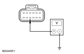
|
Yes GO to AB6. No REPAIR the circuit. REPEAT the self-test. CLEAR the DTCs. If equipped with seat side air bags, DISCONNECT the battery ground cable. DISCONNECT the restraint system diagnostic tool from driver seat side air bag module C327 and CONNECT driver seat side air bag module C327. DISCONNECT the restraint system diagnostic tool from passenger seat side air bag module C313 and CONNECT passenger seat side air bag module C313. REPOWER the SRS. REFER to Section 501-20B. | ||||||||||||
| AB6 CHECK THE BACKREST TED+ CIRCUIT FOR SHORT TO GROUND | |||||||||||||
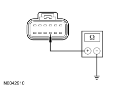
|
Yes GO to AB7. No REPAIR the circuit. REPEAT the self-test. CLEAR the DTCs. If equipped with seat side air bags, DISCONNECT the battery ground cable. DISCONNECT the restraint system diagnostic tool from driver seat side air bag module C327 and CONNECT driver seat side air bag module C327. DISCONNECT the restraint system diagnostic tool from passenger seat side air bag module C313 and CONNECT passenger seat side air bag module C313. REPOWER the SRS. REFER to Section 501-20B. | ||||||||||||
| AB7 CHECK RESISTANCE OF THE BACKREST TED AND WIRING | |||||||||||||
|
Yes GO to AB9. No GO to AB8. | ||||||||||||
| AB8 CHECK RESISTANCE OF THE BACKREST TED | |||||||||||||
|
Yes REPAIR the affected circuit(s). REPEAT the self-test. CLEAR the DTCs. If equipped with seat side air bags, DISCONNECT the battery ground cable. DISCONNECT the restraint system diagnostic tool from driver seat side air bag module C327 and CONNECT driver seat side air bag module C327. DISCONNECT the restraint system diagnostic tool from passenger seat side air bag module C313 and CONNECT passenger seat side air bag module C313. REPOWER the SRS. REFER to Section 501-20B. No INSTALL a new backrest TED. REPEAT the self-test. CLEAR the DTCs. If equipped with seat side air bags, DISCONNECT the battery ground cable. DISCONNECT the restraint system diagnostic tool from driver seat side air bag module C327 and CONNECT driver seat side air bag module C327. DISCONNECT the restraint system diagnostic tool from passenger seat side air bag module C313 and CONNECT passenger seat side air bag module C313. REPOWER the SRS. REFER to Section 501-20B. | ||||||||||||
| AB9 CHECK THE BLOWER+ AND SPEED CONTROL CIRCUITS FOR A SHORT TO VOLTAGE | |||||||||||||
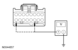
|
Yes GO to AB10. No REPAIR the circuit. REPEAT the self-test. CLEAR the DTCs. If equipped with seat side air bags, DISCONNECT the battery ground cable. DISCONNECT the restraint system diagnostic tool from driver seat side air bag module C327 and CONNECT driver seat side air bag module C327. DISCONNECT the restraint system diagnostic tool from passenger seat side air bag module C313 and CONNECT passenger seat side air bag module C313. REPOWER the SRS. REFER to Section 501-20B. | ||||||||||||
| AB10 CHECK THE BLOWER AND SPEED CONTROL CIRCUITS FOR A SHORT TO GROUND | |||||||||||||
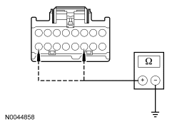
|
Yes GO to AB11. No REPAIR the circuit. REPEAT the self-test. CLEAR the DTCs. If equipped with seat side air bags, DISCONNECT the battery ground cable. DISCONNECT the restraint system diagnostic tool from driver seat side air bag module C327 and CONNECT driver seat side air bag module C327. DISCONNECT the restraint system diagnostic tool from passenger seat side air bag module C313 and CONNECT passenger seat side air bag module C313. REPOWER the SRS. REFER to Section 501-20B. | ||||||||||||
| AB11 CHECK THE BLOWER AND WIRING | |||||||||||||
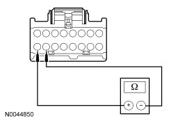
|
Yes GO to AB13. No GO to AB12. | ||||||||||||
| AB12 CHECK THE BLOWER | |||||||||||||
|
Yes REPAIR the affected circuit(s). REPEAT the self-test. CLEAR the DTCs. If equipped with seat side air bags, DISCONNECT the battery ground cable. DISCONNECT the restraint system diagnostic tool from driver seat side air bag module C327 and CONNECT driver seat side air bag module C327. DISCONNECT the restraint system diagnostic tool from passenger seat side air bag module C313 and CONNECT passenger seat side air bag module C313. REPOWER the SRS. REFER to Section 501-20B. No INSTALL a new cushion TED. REPEAT the self-test. CLEAR the DTCs. If equipped with seat side air bags, DISCONNECT the battery ground cable. DISCONNECT the restraint system diagnostic tool from driver seat side air bag module C327 and CONNECT driver seat side air bag module C327. DISCONNECT the restraint system diagnostic tool from passenger seat side air bag module C313 and CONNECT passenger seat side air bag module C313. REPOWER the SRS. REFER to Section 501-20B. | ||||||||||||
| AB13 CHECK BLOWER SPEED CONTROL AND CIRCUIT | |||||||||||||
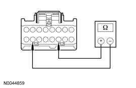
|
Yes GO to AB15. No GO to AB14. | ||||||||||||
| AB14 CHECK THE BLOWER SPEED CONTROL | |||||||||||||
|
Yes REPAIR the affected circuit(s). REPEAT the self-test. CLEAR the DTCs. If equipped with seat side air bags, DISCONNECT the battery ground cable. DISCONNECT the restraint system diagnostic tool from driver seat side air bag module C327 and CONNECT driver seat side air bag module C327. DISCONNECT the restraint system diagnostic tool from passenger seat side air bag module C313 and CONNECT passenger seat side air bag module C313. REPOWER the SRS. REFER to Section 501-20B. No INSTALL a new cushion TED. REPEAT the self-test. CLEAR the DTCs. If equipped with seat side air bags, DISCONNECT the battery ground cable. DISCONNECT the restraint system diagnostic tool from driver seat side air bag module C327 and CONNECT driver seat side air bag module C327. DISCONNECT the restraint system diagnostic tool from passenger seat side air bag module C313 and CONNECT passenger seat side air bag module C313. REPOWER the SRS. REFER to Section 501-20B. | ||||||||||||
| AB15 CHECK THERMISTOR CIRCUIT FOR A SHORT TO VOLTAGE | |||||||||||||
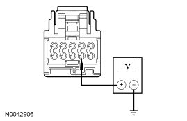
|
Yes REPAIR the circuit. REPEAT the self-test. CLEAR the DTCs. If equipped with seat side air bags, DISCONNECT the battery ground cable. DISCONNECT the restraint system diagnostic tool from driver seat side air bag module C327 and CONNECT driver seat side air bag module C327. DISCONNECT the restraint system diagnostic tool from passenger seat side air bag module C313 and CONNECT passenger seat side air bag module C313. REPOWER the SRS. REFER to Section 501-20B. No GO to AB16. | ||||||||||||
| AB16 CHECK THERMISTOR CIRCUIT FOR A SHORT TO GROUND | |||||||||||||
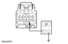
|
Yes GO to AB17. No REPAIR the circuit. REPEAT the self-test. CLEAR the DTCs. If equipped with seat side air bags, DISCONNECT the battery ground cable. DISCONNECT the restraint system diagnostic tool from driver seat side air bag module C327 and CONNECT driver seat side air bag module C327. DISCONNECT the restraint system diagnostic tool from passenger seat side air bag module C313 and CONNECT passenger seat side air bag module C313. REPOWER the SRS. REFER to Section 501-20B. | ||||||||||||
| AB17 CHECK THE THERMISTOR AND WIRING | |||||||||||||
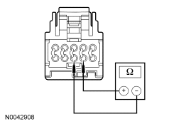
|
Yes INSTALL a new DCSM and CARRY OUT programmable module installation (PMI). REFER to Climate Controlled Seat Module. REPEAT the self-test. CLEAR the DTCs. If equipped with seat side air bags, DISCONNECT the battery ground cable. DISCONNECT the restraint system diagnostic tool from driver seat side air bag module C327 and CONNECT driver seat side air bag module C327. DISCONNECT the restraint system diagnostic tool from passenger seat side air bag module C313 and CONNECT passenger seat side air bag module C313. REPOWER the SRS. REFER to Section 501-20B. No GO to AB18. | ||||||||||||
| AB18 CHECK THE THERMISTOR | |||||||||||||
|
Yes REPAIR the affected circuit(s). REPEAT the self-test. CLEAR the DTCs. If equipped with seat side air bags, DISCONNECT the battery ground cable. DISCONNECT the restraint system diagnostic tool from driver seat side air bag module C327 and CONNECT driver seat side air bag module C327. DISCONNECT the restraint system diagnostic tool from passenger seat side air bag module C313 and CONNECT passenger seat side air bag module C313. REPOWER the SRS. REFER to Section 501-20B. No INSTALL a new cushion TED. REPEAT the self-test. CLEAR the DTCs. If equipped with seat side air bags, DISCONNECT the battery ground cable. DISCONNECT the restraint system diagnostic tool from driver seat side air bag module C327 and CONNECT driver seat side air bag module C327. DISCONNECT the restraint system diagnostic tool from passenger seat side air bag module C313 and CONNECT passenger seat side air bag module C313. REPOWER the SRS. REFER to Section 501-20B. | ||||||||||||
| AB19 CHECK THE TED INSTALLATION AND FOR A CRUSHED SEAT BACKREST | |||||||||||||
|
Yes GO to AB20. No CORRECTLY install the backrest TED or INSTALL a new seat backrest foam pad and/or climate controlled seat manifold. REPEAT the self-test. CLEAR the DTCs. If equipped with seat side air bags, DISCONNECT the battery ground cable. DISCONNECT the restraint system diagnostic tool from driver seat side air bag module C327 and CONNECT driver seat side air bag module C327. DISCONNECT the restraint system diagnostic tool from passenger seat side air bag module C313 and CONNECT passenger seat side air bag module C313. REPOWER the SRS. REFER to Section 501-20B. | ||||||||||||
| AB20 CHECK THE CUSHION TED- CIRCUIT FOR SHORT TO VOLTAGE | |||||||||||||
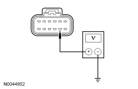
|
Yes GO to AB21. No REPAIR the circuit. REPEAT the self-test. CLEAR the DTCs. If equipped with seat side air bags, DISCONNECT the battery ground cable. DISCONNECT the restraint system diagnostic tool from driver seat side air bag module C327 and CONNECT driver seat side air bag module C327. DISCONNECT the restraint system diagnostic tool from passenger seat side air bag module C313 and CONNECT passenger seat side air bag module C313. REPOWER the SRS. REFER to Section 501-20B. | ||||||||||||
| AB21 CHECK THE CUSHION TED+ CIRCUIT FOR SHORT TO GROUND | |||||||||||||
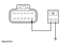
|
Yes GO to AB22. No REPAIR the circuit. REPEAT the self-test. CLEAR the DTCs. If equipped with seat side air bags, DISCONNECT the battery ground cable. DISCONNECT the restraint system diagnostic tool from driver seat side air bag module C327 and CONNECT driver seat side air bag module C327. DISCONNECT the restraint system diagnostic tool from passenger seat side air bag module C313 and CONNECT passenger seat side air bag module C313. REPOWER the SRS. REFER to Section 501-20B. | ||||||||||||
| AB22 CHECK RESISTANCE OF THE CUSHION TED AND WIRING | |||||||||||||
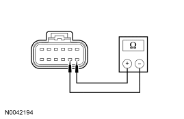
|
Yes GO to AB24. No GO to AB23. | ||||||||||||
| AB23 CHECK RESISTANCE OF THE CUSHION TED | |||||||||||||
|
Yes REPAIR the circuit. REPEAT the self-test. CLEAR the DTCs. If equipped with seat side air bags, DISCONNECT the battery ground cable. DISCONNECT the restraint system diagnostic tool from driver seat side air bag module C327 and CONNECT driver seat side air bag module C327. DISCONNECT the restraint system diagnostic tool from passenger seat side air bag module C313 and CONNECT passenger seat side air bag module C313. REPOWER the SRS. REFER to Section 501-20B. No INSTALL a new cushion TED. REPEAT the self-test. CLEAR the DTCs. If equipped with seat side air bags, DISCONNECT the battery ground cable. DISCONNECT the restraint system diagnostic tool from driver seat side air bag module C327 and CONNECT driver seat side air bag module C327. DISCONNECT the restraint system diagnostic tool from passenger seat side air bag module C313 and CONNECT passenger seat side air bag module C313. REPOWER the SRS. REFER to Section 501-20B. | ||||||||||||
| AB24 CHECK THE BLOWER+ AND SPEED CONTROL CIRCUITS FOR A SHORT TO VOLTAGE | |||||||||||||
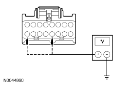
|
Yes GO to AB25. No REPAIR the circuit. REPEAT the self-test. CLEAR the DTCs. If equipped with seat side air bags, DISCONNECT the battery ground cable. DISCONNECT the restraint system diagnostic tool from driver seat side air bag module C327 and CONNECT driver seat side air bag module C327. DISCONNECT the restraint system diagnostic tool from passenger seat side air bag module C313 and CONNECT passenger seat side air bag module C313. REPOWER the SRS. REFER to Section 501-20B. | ||||||||||||
| AB25 CHECK THE BLOWER AND SPEED CONTROL CIRCUITS FOR A SHORT TO GROUND | |||||||||||||
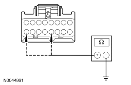
|
Yes GO to AB26. No REPAIR the circuit. REPEAT the self-test. CLEAR the DTCs. If equipped with seat side air bags, DISCONNECT the battery ground cable. DISCONNECT the restraint system diagnostic tool from driver seat side air bag module C327 and CONNECT driver seat side air bag module C327. DISCONNECT the restraint system diagnostic tool from passenger seat side air bag module C313 and CONNECT passenger seat side air bag module C313. REPOWER the SRS. REFER to Section 501-20B. | ||||||||||||
| AB26 CHECK THE BLOWER AND WIRING | |||||||||||||
|
Yes GO to AB28. No GO to AB27. | ||||||||||||
| AB27 CHECK THE BLOWER | |||||||||||||
|
Yes REPAIR the affected circuit(s). REPEAT the self-test. CLEAR the DTCs. If equipped with seat side air bags, DISCONNECT the battery ground cable. DISCONNECT the restraint system diagnostic tool from driver seat side air bag module C327 and CONNECT driver seat side air bag module C327. DISCONNECT the restraint system diagnostic tool from passenger seat side air bag module C313 and CONNECT passenger seat side air bag module C313. REPOWER the SRS. REFER to Section 501-20B. No INSTALL a new backrest TED. REPEAT the self-test. CLEAR the DTCs. If equipped with seat side air bags, DISCONNECT the battery ground cable. DISCONNECT the restraint system diagnostic tool from driver seat side air bag module C327 and CONNECT driver seat side air bag module C327. DISCONNECT the restraint system diagnostic tool from passenger seat side air bag module C313 and CONNECT passenger seat side air bag module C313. REPOWER the SRS. REFER to Section 501-20B. | ||||||||||||
| AB28 CHECK BLOWER SPEED CONTROL AND CIRCUIT | |||||||||||||
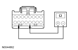
|
Yes GO to AB30. No GO to AB29. | ||||||||||||
| AB29 CHECK THE BLOWER SPEED CONTROL | |||||||||||||
|
Yes REPAIR the affected circuit(s). REPEAT the self-test. CLEAR the DTCs. If equipped with seat side air bags, DISCONNECT the battery ground cable. DISCONNECT the restraint system diagnostic tool from driver seat side air bag module C327 and CONNECT driver seat side air bag module C327. DISCONNECT the restraint system diagnostic tool from passenger seat side air bag module C313 and CONNECT passenger seat side air bag module C313. REPOWER the SRS. REFER to Section 501-20B. No INSTALL a new backrest TED. REPEAT the self-test. CLEAR the DTCs. If equipped with seat side air bags, DISCONNECT the battery ground cable. DISCONNECT the restraint system diagnostic tool from driver seat side air bag module C327 and CONNECT driver seat side air bag module C327. DISCONNECT the restraint system diagnostic tool from passenger seat side air bag module C313 and CONNECT passenger seat side air bag module C313. REPOWER the SRS. REFER to Section 501-20B. | ||||||||||||
| AB30 CHECK THERMISTOR CIRCUIT FOR A SHORT TO VOLTAGE | |||||||||||||
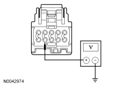
|
Yes REPAIR the circuit. REPEAT the self-test. CLEAR the DTCs. If equipped with seat side air bags, DISCONNECT the battery ground cable. DISCONNECT the restraint system diagnostic tool from driver seat side air bag module C327 and CONNECT driver seat side air bag module C327. DISCONNECT the restraint system diagnostic tool from passenger seat side air bag module C313 and CONNECT passenger seat side air bag module C313. REPOWER the SRS. REFER to Section 501-20B. No GO to AB31. | ||||||||||||
| AB31 CHECK THERMISTOR CIRCUIT FOR A SHORT TO GROUND | |||||||||||||
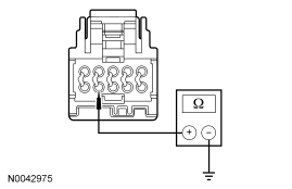
|
Yes GO to AB32. No REPAIR the circuit. REPEAT the self-test. CLEAR the DTCs. If equipped with seat side air bags, DISCONNECT the battery ground cable. DISCONNECT the restraint system diagnostic tool from driver seat side air bag module C327 and CONNECT driver seat side air bag module C327. DISCONNECT the restraint system diagnostic tool from passenger seat side air bag module C313 and CONNECT passenger seat side air bag module C313. REPOWER the SRS. REFER to Section 501-20B. | ||||||||||||
| AB32 CHECK THE THERMISTOR AND WIRING | |||||||||||||
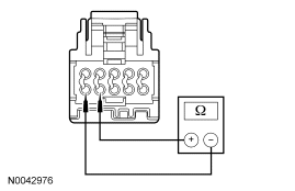
|
Yes INSTALL a new DCSM and CARRY OUT programmable module installation (PMI). REFER to Climate Controlled Seat Module. REPEAT the self-test. CLEAR the DTCs. If equipped with seat side air bags, DISCONNECT the battery ground cable. DISCONNECT the restraint system diagnostic tool from driver seat side air bag module C327 and CONNECT driver seat side air bag module C327. DISCONNECT the restraint system diagnostic tool from passenger seat side air bag module C313 and CONNECT passenger seat side air bag module C313. REPOWER the SRS. REFER to Section 501-20B. No GO to AB33. | ||||||||||||
| AB33 CHECK THE THERMISTOR | |||||||||||||
|
Yes REPAIR the affected circuit(s). REPEAT the self-test. CLEAR the DTCs. If equipped with seat side air bags, DISCONNECT the battery ground cable. DISCONNECT the restraint system diagnostic tool from driver seat side air bag module C327 and CONNECT driver seat side air bag module C327. DISCONNECT the restraint system diagnostic tool from passenger seat side air bag module C313 and CONNECT passenger seat side air bag module C313. REPOWER the SRS. REFER to Section 501-20B. No INSTALL a new backrest TED. REPEAT the self-test. CLEAR the DTCs. If equipped with seat side air bags, DISCONNECT the battery ground cable. DISCONNECT the restraint system diagnostic tool from driver seat side air bag module C327 and CONNECT driver seat side air bag module C327. DISCONNECT the restraint system diagnostic tool from passenger seat side air bag module C313 and CONNECT passenger seat side air bag module C313. REPOWER the SRS. REFER to Section 501-20B. |
Pinpoint Test AC: DTC B272D — Passenger Differential Temperature Fault
Refer to Wiring Diagrams Cell 119, Climate Controlled Seats for schematic and connector information.
Normal Operation
Both the driver and front passenger climate controlled seats are independently controlled electronically by the dual climate controlled seat module (DCSM) mounted to the bottom of the passenger seat cushion. The climate controlled seat system only operates with the engine running, however, if using a scan tool to command the DCSM, diagnostic testing can be carried out with the ignition switch key ON engine OFF (KOEO). The system receives power from battery junction box (BJB) fuse 12 (30A) feeding battery voltage on circuit SBB12 (GN/RD) into DCSM C3305a pin F. The system also receives power from BJB fuse 11 (30A) feeding battery voltage on circuit SBB11 (BU/RD) into DCSM C3305a pin E. If power is disconnected from either pin E or F of DCSM C3305a with the power connection remaining on the other circuit, both seats will remain operational because the power feed circuits are connected internally in the DCSM. However, if a fault occurs setting a DTC specific to either climate controlled seat, only the affected seat will be disabled by the module and the other will remain operational.
Each driver and front passenger seat cushion is equipped with a thermo-electric device (TED) assembly that includes a seat blower (fan motor, serviced as an assembly with the TED). Similarly, each driver and front passenger seat backrest is also equipped with its own TED assembly with blower. Cabin air is drawn through the blower and distributed to each of the TED modules located in the seat cushion and backrest. The TEDs then heat or cool the air. The air is then directed into the foam pad and manifold where it is distributed along the surface of the cushion and backrest of the seat. Once the system is activated, the DCSM uses a set of flexible algorithms to control the heating/cooling modes and the blower speed dependant on the EATC seat switch settings.
A differential fault occurs when the cushion and backrest TEDs on an affected seat are reporting very different temperatures to the DCSM. This may result from an airflow restriction or a circuit fault of either TED area. If a TED and manifold is clear of obstruction and is operational, the other TED and circuitry on the seat should be checked. It is important to note that a TED with a higher temperature may be operating correctly and not the area of concern. The other TED may be indicating a much lower temperature, causing the DTC to set.
Possible Causes
A driver differential temperature fault can be caused by:
- wiring, terminals or connectors.
- restricted cushion or backrest TED filter.
- crushed or restricted cushion or backrest foam pad.
- crushed or restricted cushion or backrest climate controlled seat manifold.
- a faulted cushion or backrest TED assembly.
- a faulted DCSM.
PINPOINT TEST AC: DTC B272D — PASSENGER DIFFERENTIAL TEMPERATURE FAULT
| Test Step | Result / Action to Take | ||||||||||||
|---|---|---|---|---|---|---|---|---|---|---|---|---|---|
| AC1 CHECK THE DCSM FOR ON-DEMAND DTCS | |||||||||||||
|
Yes For DTC B272A, Go To Pinpoint Test Z. For DTC B272B, Go To Pinpoint Test AA. No GO to AC2. | ||||||||||||
| AC2 MONITOR THE DCSM TED TEMPERATURE PIDS | |||||||||||||
|
Yes GO to AC3. No If the front passenger seat cushion PID varies 10°C (18°F) or more from ambient temperature, GO to AC15 . If the front passenger seat backrest PID varies 10°C (18°F) or more from ambient temperature, GO to AC31 . | ||||||||||||
| AC3 CONFIRM THE FAULT IS IN THE SEAT CUSHION OR THE BACKREST | |||||||||||||
|
Yes If the front passenger seat cushion PID is 10°C (18°F) hotter than the backrest PID, GO to AC4 . If the front passenger seat backrest PID is 10°C (18°F) hotter than the cushion PID, GO to AC19 . No Fault is currently not present. INSPECT for crushed seat cushion or backrest foam pad or climate controlled seat cushion or backrest manifold. CHECK for an intermittent wiring fault. REPAIR as needed. REPEAT the self-test. CLEAR the DTCs. If equipped with seat side air bags, DISCONNECT the battery ground cable. DISCONNECT the restraint system diagnostic tool from passenger seat side air bag module C313 and CONNECT passenger seat side air bag module C313. REPOWER the SRS. REFER to Section 501-20B. | ||||||||||||
| AC4 CHECK THE TED INSTALLATION AND FOR A CRUSHED SEAT CUSHION | |||||||||||||
|
Yes GO to AC5. No CORRECTLY install the cushion TED or INSTALL a new seat cushion foam pad and/or climate controlled seat manifold. REPEAT the self-test. CLEAR the DTCs. If equipped with seat side air bags, DISCONNECT the battery ground cable. DISCONNECT the restraint system diagnostic tool from passenger seat side air bag module C313 and CONNECT passenger seat side air bag module C313. REPOWER the SRS. REFER to Section 501-20B. | ||||||||||||
| AC5 CHECK THE BACKREST TED- CIRCUIT FOR SHORT TO VOLTAGE | |||||||||||||
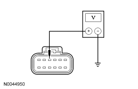
|
Yes GO to AC6. No REPAIR the circuit. REPEAT the self-test. CLEAR the DTCs. If equipped with seat side air bags, DISCONNECT the battery ground cable. DISCONNECT the restraint system diagnostic tool from passenger seat side air bag module C313 and CONNECT passenger seat side air bag module C313. REPOWER the SRS. REFER to Section 501-20B. | ||||||||||||
| AC6 CHECK THE BACKREST TED+ CIRCUIT FOR SHORT TO GROUND | |||||||||||||
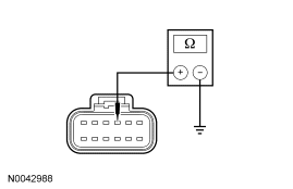
|
Yes GO to AC7. No REPAIR the circuit. REPEAT the self-test. CLEAR the DTCs. If equipped with seat side air bags, DISCONNECT the battery ground cable. DISCONNECT the restraint system diagnostic tool from passenger seat side air bag module C313 and CONNECT passenger seat side air bag module C313. REPOWER the SRS. REFER to Section 501-20B. | ||||||||||||
| AC7 CHECK RESISTANCE OF THE BACKREST TED AND WIRING | |||||||||||||
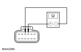
|
Yes GO to AC9. No GO to AC8. | ||||||||||||
| AC8 CHECK RESISTANCE OF THE BACKREST TED | |||||||||||||
|
Yes REPAIR the circuit. REPEAT the self-test. CLEAR the DTCs. If equipped with seat side air bags, DISCONNECT the battery ground cable. DISCONNECT the restraint system diagnostic tool from passenger seat side air bag module C313 and CONNECT passenger seat side air bag module C313. REPOWER the SRS. REFER to Section 501-20B. No INSTALL a new backrest TED. REPEAT the self-test. CLEAR the DTCs. If equipped with seat side air bags, DISCONNECT the battery ground cable. DISCONNECT the restraint system diagnostic tool from passenger seat side air bag module C313 and CONNECT passenger seat side air bag module C313. REPOWER the SRS. REFER to Section 501-20B. | ||||||||||||
| AC9 CHECK THE BLOWER+ AND SPEED CONTROL CIRCUITS FOR A SHORT TO VOLTAGE | |||||||||||||
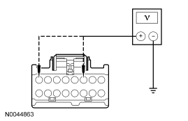
|
Yes GO to AC10. No REPAIR the circuit. REPEAT the self-test. CLEAR the DTCs. If equipped with seat side air bags, DISCONNECT the battery ground cable. DISCONNECT the restraint system diagnostic tool from passenger seat side air bag module C313 and CONNECT passenger seat side air bag module C313. REPOWER the SRS. REFER to Section 501-20B. | ||||||||||||
| AC10 CHECK THE BLOWER AND SPEED CONTROL CIRCUITS FOR A SHORT TO GROUND | |||||||||||||
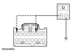
|
Yes GO to AC11. No REPAIR the circuit. REPEAT the self-test. CLEAR the DTCs. If equipped with seat side air bags, DISCONNECT the battery ground cable. DISCONNECT the restraint system diagnostic tool from passenger seat side air bag module C313 and CONNECT passenger seat side air bag module C313. REPOWER the SRS. REFER to Section 501-20B. | ||||||||||||
| AC11 CHECK THE BLOWER AND WIRING | |||||||||||||
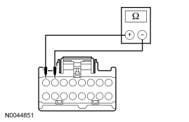
|
Yes GO to AC13. No GO to AC12. | ||||||||||||
| AC12 CHECK THE BLOWER | |||||||||||||
|
Yes REPAIR the affected circuit(s). REPEAT the self-test. CLEAR the DTCs. If equipped with seat side air bags, DISCONNECT the battery ground cable. DISCONNECT the restraint system diagnostic tool from passenger seat side air bag module C313 and CONNECT passenger seat side air bag module C313. REPOWER the SRS. REFER to Section 501-20B. No INSTALL a new cushion TED. REPEAT the self-test. CLEAR the DTCs. If equipped with seat side air bags, DISCONNECT the battery ground cable. DISCONNECT the restraint system diagnostic tool from passenger seat side air bag module C313 and CONNECT passenger seat side air bag module C313. REPOWER the SRS. REFER to Section 501-20B. | ||||||||||||
| AC13 CHECK BLOWER SPEED CONTROL AND CIRCUIT | |||||||||||||
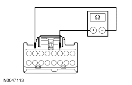
|
Yes GO to AC15. No GO to AC14. | ||||||||||||
| AC14 CHECK THE BLOWER SPEED CONTROL | |||||||||||||
|
Yes REPAIR the affected circuit(s). REPEAT the self-test. CLEAR the DTCs. If equipped with seat side air bags, DISCONNECT the battery ground cable. DISCONNECT the restraint system diagnostic tool from passenger seat side air bag module C313 and CONNECT passenger seat side air bag module C313. REPOWER the SRS. REFER to Section 501-20B. No INSTALL a new cushion TED. REPEAT the self-test. CLEAR the DTCs. If equipped with seat side air bags, DISCONNECT the battery ground cable. DISCONNECT the restraint system diagnostic tool from passenger seat side air bag module C313 and CONNECT passenger seat side air bag module C313. REPOWER the SRS. REFER to Section 501-20B. | ||||||||||||
| AC15 CHECK THERMISTOR CIRCUIT FOR A SHORT TO VOLTAGE | |||||||||||||
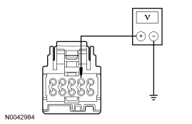
|
Yes REPAIR the circuit. REPEAT the self-test. CLEAR the DTCs. If equipped with seat side air bags, DISCONNECT the battery ground cable. DISCONNECT the restraint system diagnostic tool from passenger seat side air bag module C313 and CONNECT passenger seat side air bag module C313. REPOWER the SRS. REFER to Section 501-20B. No GO to AC16. | ||||||||||||
| AC16 CHECK THERMISTOR CIRCUIT FOR A SHORT TO GROUND | |||||||||||||
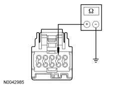
|
Yes GO to AC17. No REPAIR the circuit. REPEAT the self-test. CLEAR the DTCs. If equipped with seat side air bags, DISCONNECT the battery ground cable. DISCONNECT the restraint system diagnostic tool from passenger seat side air bag module C313 and CONNECT passenger seat side air bag module C313. REPOWER the SRS. REFER to Section 501-20B. | ||||||||||||
| AC17 CHECK THE THERMISTOR AND WIRING | |||||||||||||
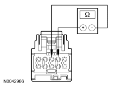
|
Yes INSTALL a new DCSM and CARRY OUT programmable module installation (PMI). REFER to Climate Controlled Seat Module. REPEAT the self-test. CLEAR the DTCs. If equipped with seat side air bags, DISCONNECT the battery ground cable. DISCONNECT the restraint system diagnostic tool from passenger seat side air bag module C313 and CONNECT passenger seat side air bag module C313. REPOWER the SRS. REFER to Section 501-20B. No GO to AC18. | ||||||||||||
| AC18 CHECK THE THERMISTOR | |||||||||||||
|
Yes REPAIR the affected circuit(s). REPEAT the self-test. CLEAR the DTCs. If equipped with seat side air bags, DISCONNECT the battery ground cable. DISCONNECT the restraint system diagnostic tool from passenger seat side air bag module C313 and CONNECT passenger seat side air bag module C313. REPOWER the SRS. REFER to Section 501-20B. No INSTALL a new cushion TED. REPEAT the self-test. CLEAR the DTCs. If equipped with seat side air bags, DISCONNECT the battery ground cable. DISCONNECT the restraint system diagnostic tool from passenger seat side air bag module C313 and CONNECT passenger seat side air bag module C313. REPOWER the SRS. REFER to Section 501-20B. | ||||||||||||
| AC19 CHECK THE TED INSTALLATION AND FOR A CRUSHED SEAT BACKREST | |||||||||||||
|
Yes GO to AC20. No CORRECTLY install the backrest TED or INSTALL a new seat backrest foam pad and/or climate controlled seat manifold. REPEAT the self-test. CLEAR the DTCs. If equipped with seat side air bags, DISCONNECT the battery ground cable. DISCONNECT the restraint system diagnostic tool from passenger seat side air bag module C313 and CONNECT passenger seat side air bag module C313. REPOWER the SRS. REFER to Section 501-20B. | ||||||||||||
| AC20 CHECK THE CUSHION TED- CIRCUIT FOR SHORT TO VOLTAGE | |||||||||||||
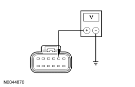
|
Yes GO to AC21. No REPAIR the circuit. REPEAT the self-test. CLEAR the DTCs. If equipped with seat side air bags, DISCONNECT the battery ground cable. DISCONNECT the restraint system diagnostic tool from passenger seat side air bag module C313 and CONNECT passenger seat side air bag module C313. REPOWER the SRS. REFER to Section 501-20B. | ||||||||||||
| AC21 CHECK THE CUSHION TED+ CIRCUIT FOR SHORT TO GROUND | |||||||||||||
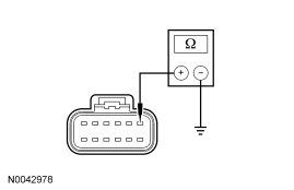
|
Yes GO to AC22. No REPAIR the circuit. REPEAT the self-test. CLEAR the DTCs. If equipped with seat side air bags, DISCONNECT the battery ground cable. DISCONNECT the restraint system diagnostic tool from passenger seat side air bag module C313 and CONNECT passenger seat side air bag module C313. REPOWER the SRS. REFER to Section 501-20B. | ||||||||||||
| AC22 CHECK RESISTANCE OF THE CUSHION TED AND WIRING | |||||||||||||
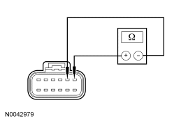
|
Yes GO to AC24. No GO to AC23. | ||||||||||||
| AC23 CHECK RESISTANCE OF THE CUSHION TED | |||||||||||||
|
Yes REPAIR the circuit. REPEAT the self-test. CLEAR the DTCs. If equipped with seat side air bags, DISCONNECT the battery ground cable. DISCONNECT the restraint system diagnostic tool from passenger seat side air bag module C313 and CONNECT passenger seat side air bag module C313. REPOWER the SRS. REFER to Section 501-20B. No INSTALL a new cushion TED. REPEAT the self-test. CLEAR the DTCs. If equipped with seat side air bags, DISCONNECT the battery ground cable. DISCONNECT the restraint system diagnostic tool from passenger seat side air bag module C313 and CONNECT passenger seat side air bag module C313. REPOWER the SRS. REFER to Section 501-20B. | ||||||||||||
| AC24 CHECK THE BLOWER+ AND SPEED CONTROL CIRCUITS FOR A SHORT TO VOLTAGE | |||||||||||||
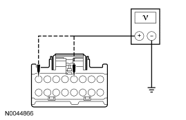
|
Yes GO to AC25. No REPAIR the circuit. REPEAT the self-test. CLEAR the DTCs. If equipped with seat side air bags, DISCONNECT the battery ground cable. DISCONNECT the restraint system diagnostic tool from passenger seat side air bag module C313 and CONNECT passenger seat side air bag module C313. REPOWER the SRS. REFER to Section 501-20B. | ||||||||||||
| AC25 CHECK THE BLOWER AND SPEED CONTROL CIRCUITS FOR A SHORT TO GROUND | |||||||||||||
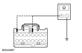
|
Yes GO to AC26. No REPAIR the circuit. REPEAT the self-test. CLEAR the DTCs. If equipped with seat side air bags, DISCONNECT the battery ground cable. DISCONNECT the restraint system diagnostic tool from passenger seat side air bag module C313 and CONNECT passenger seat side air bag module C313. REPOWER the SRS. REFER to Section 501-20B. | ||||||||||||
| AC26 CHECK THE BLOWER AND WIRING | |||||||||||||
|
Yes GO to AC28. No GO to AC27. | ||||||||||||
| AC27 CHECK THE BLOWER | |||||||||||||
|
Yes REPAIR the affected circuit(s). REPEAT the self-test. CLEAR the DTCs. If equipped with seat side air bags, DISCONNECT the battery ground cable. DISCONNECT the restraint system diagnostic tool from passenger seat side air bag module C313 and CONNECT passenger seat side air bag module C313. REPOWER the SRS. REFER to Section 501-20B. No INSTALL a new backrest TED. REPEAT the self-test. CLEAR the DTCs. If equipped with seat side air bags, DISCONNECT the battery ground cable. DISCONNECT the restraint system diagnostic tool from passenger seat side air bag module C313 and CONNECT passenger seat side air bag module C313. REPOWER the SRS. REFER to Section 501-20B. | ||||||||||||
| AC28 CHECK BLOWER SPEED CONTROL AND CIRCUIT | |||||||||||||
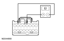
|
Yes GO to AC30. No GO to AC29. | ||||||||||||
| AC29 CHECK THE BLOWER SPEED CONTROL | |||||||||||||
|
Yes REPAIR the affected circuit(s). REPEAT the self-test. CLEAR the DTCs. If equipped with seat side air bags, DISCONNECT the battery ground cable. DISCONNECT the restraint system diagnostic tool from passenger seat side air bag module C313 and CONNECT passenger seat side air bag module C313. REPOWER the SRS. REFER to Section 501-20B. No INSTALL a new backrest TED. REPEAT the self-test. CLEAR the DTCs. If equipped with seat side air bags, DISCONNECT the battery ground cable. DISCONNECT the restraint system diagnostic tool from passenger seat side air bag module C313 and CONNECT passenger seat side air bag module C313. REPOWER the SRS. REFER to Section 501-20B. | ||||||||||||
| AC30 CHECK THERMISTOR CIRCUIT FOR A SHORT TO VOLTAGE | |||||||||||||
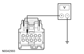
|
Yes REPAIR the circuit. REPEAT the self-test. CLEAR the DTCs. If equipped with seat side air bags, DISCONNECT the battery ground cable. DISCONNECT the restraint system diagnostic tool from passenger seat side air bag module C313 and CONNECT passenger seat side air bag module C313. REPOWER the SRS. REFER to Section 501-20B. No GO to AC31. | ||||||||||||
| AC31 CHECK THERMISTOR CIRCUIT FOR A SHORT TO GROUND | |||||||||||||
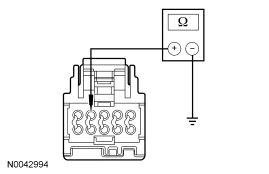
|
Yes GO to AC32. No REPAIR the circuit. REPEAT the self-test. CLEAR the DTCs. If equipped with seat side air bags, DISCONNECT the battery ground cable. DISCONNECT the restraint system diagnostic tool from passenger seat side air bag module C313 and CONNECT passenger seat side air bag module C313. REPOWER the SRS. REFER to Section 501-20B. | ||||||||||||
| AC32 CHECK THE THERMISTOR AND WIRING | |||||||||||||
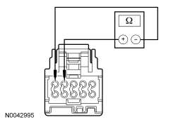
|
Yes INSTALL a new DCSM and CARRY OUT programmable module installation (PMI). REFER to Climate Controlled Seat Module. REPEAT the self-test. CLEAR the DTCs. If equipped with seat side air bags, DISCONNECT the battery ground cable. DISCONNECT the restraint system diagnostic tool from passenger seat side air bag module C313 and CONNECT passenger seat side air bag module C313. REPOWER the SRS. REFER to Section 501-20B. No GO to AC33. | ||||||||||||
| AC33 CHECK THE THERMISTOR | |||||||||||||
|
Yes REPAIR the affected circuit(s). REPEAT the self-test. CLEAR the DTCs. If equipped with seat side air bags, DISCONNECT the battery ground cable. DISCONNECT the restraint system diagnostic tool from passenger seat side air bag module C313 and CONNECT passenger seat side air bag module C313. REPOWER the SRS. REFER to Section 501-20B. No INSTALL a new backrest TED. REPEAT the self-test. CLEAR the DTCs. If equipped with seat side air bags, DISCONNECT the battery ground cable. DISCONNECT the restraint system diagnostic tool from passenger seat side air bag module C313 and CONNECT passenger seat side air bag module C313. REPOWER the SRS. REFER to Section 501-20B. |
Pinpoint Test AD: DTC B2730 — Back Over-Temp Detected (Driver)
Refer to Wiring Diagrams Cell 119, Climate Controlled Seats for schematic and connector information.
Normal Operation
Both the driver and front passenger climate controlled seats are independently controlled electronically by the dual climate controlled seat module (DCSM) mounted to the bottom of the passenger seat cushion. The climate controlled seat system only operates with the engine running, however, if using a scan tool to command the DCSM, diagnostic testing can be carried out with the ignition switch key ON engine OFF (KOEO). The system receives power from battery junction box (BJB) fuse 12 (30A) feeding battery voltage on circuit SBB12 (GN/RD) into DCSM C3305a pin F. The system also receives power from BJB fuse 11 (30A) feeding battery voltage on circuit SBB11 (BU/RD) into DCSM C3305a pin E. If power is disconnected from either pin E or F of DCSM C3305a with the power connection remaining on the other circuit, both seats will remain operational because the power feed circuits are connected internally in the DCSM. However, if a fault occurs setting a DTC specific to either climate controlled seat, only the affected seat will be disabled by the module and the other will remain operational.
Each driver and front passenger seat cushion is equipped with a thermo-electric device (TED) assembly that includes a seat blower (fan motor, serviced as an assembly with the TED). Similarly, each driver and front passenger seat backrest is also equipped with its own TED assembly with blower. Cabin air is drawn through the blower and distributed to each of the TED modules located in the seat cushion and backrest. The TEDs then heat or cool the air. The air is then directed into the foam pad and manifold where it is distributed along the surface of the cushion and backrest of the seat. Once the system is activated, the DCSM uses a set of flexible algorithms to control the heating/cooling modes and the blower speed dependant on the EATC seat switch settings.
Possible Causes
A driver seat backrest over-temp fault can be caused by:
- wiring, terminals or connectors.
- restricted backrest TED filter.
- crushed or restricted backrest foam pad.
- crushed or restricted climate controlled seat manifold.
- a faulted backrest TED assembly.
- a faulted DCSM.
PINPOINT TEST AD: DTC B2730 — BACK OVER-TEMP DETECTED (DRIVER)
| Test Step | Result / Action to Take | ||||||||||||
|---|---|---|---|---|---|---|---|---|---|---|---|---|---|
| AD1 CHECK THE DCSM FOR ON-DEMAND DTCS | |||||||||||||
|
Yes GO to AD2. No GO to AD4. | ||||||||||||
| AD2 CHECK THE TED THERMISTOR CIRCUITS FOR A SHORT TO GROUND | |||||||||||||
|
Yes GO to AD3. No REPAIR the affected circuit. REPEAT the self-test. CLEAR the DTCs. If equipped with seat side air bags, DISCONNECT the battery ground cable. DISCONNECT the restraint system diagnostic tool from driver seat side air bag module C327 and CONNECT driver seat side air bag module C327. DISCONNECT the restraint system diagnostic tool from passenger seat side air bag module C313 and CONNECT passenger seat side air bag module C313. REPOWER the SRS. REFER to Section 501-20B. | ||||||||||||
| AD3 CHECK THE TED THERMISTOR | |||||||||||||
|
Yes REPAIR the affected open circuit. REPEAT the self-test. CLEAR the DTCs. If equipped with seat side air bags, DISCONNECT the battery ground cable. DISCONNECT the restraint system diagnostic tool from driver seat side air bag module C327 and CONNECT driver seat side air bag module C327. DISCONNECT the restraint system diagnostic tool from passenger seat side air bag module C313 and CONNECT passenger seat side air bag module C313. REPOWER the SRS. REFER to Section 501-20B. No INSTALL a new backrest TED. REPEAT the self-test. CLEAR the DTCs. If equipped with seat side air bags, DISCONNECT the battery ground cable. DISCONNECT the restraint system diagnostic tool from driver seat side air bag module C327 and CONNECT driver seat side air bag module C327. DISCONNECT the restraint system diagnostic tool from passenger seat side air bag module C313 and CONNECT passenger seat side air bag module C313. REPOWER the SRS. REFER to Section 501-20B. | ||||||||||||
| AD4 CONFIRM THE FAULT | |||||||||||||
|
Yes GO to AD5. No Fault not present. Fault may have been set due to a past failure or incorrect use of the climate controlled seat system by repeated switching between HEAT and COOL modes. REPEAT the self-test. CLEAR the DTCs. If equipped with seat side air bags, DISCONNECT the battery ground cable. DISCONNECT the restraint system diagnostic tool from driver seat side air bag module C327 and CONNECT driver seat side air bag module C327. DISCONNECT the restraint system diagnostic tool from passenger seat side air bag module C313 and CONNECT passenger seat side air bag module C313. REPOWER the SRS. REFER to Section 501-20B. | ||||||||||||
| AD5 CHECK OPERATION OF THE SEAT | |||||||||||||
|
Yes GO to AD14. No GO to AD6. | ||||||||||||
| AD6 CHECK THE BACKREST BLOWER FOR AN OBSTRUCTION OR RESTRICTED FILTER | |||||||||||||
|
Yes REMOVE the obstruction or INSTALL a new filter. REPEAT the self-test. CLEAR the DTCs. If equipped with seat side air bags, DISCONNECT the battery ground cable. DISCONNECT the restraint system diagnostic tool from driver seat side air bag module C327 and CONNECT driver seat side air bag module C327. DISCONNECT the restraint system diagnostic tool from passenger seat side air bag module C313 and CONNECT passenger seat side air bag module C313. REPOWER the SRS. REFER to Section 501-20B. No GO to AD7. | ||||||||||||
| AD7 CHECK THE BACKREST FAN OPERATION | |||||||||||||
|
Yes GO to AD14. No GO to AD8. | ||||||||||||
| AD8 CHECK THE BLOWER SPEED CONTROL CIRCUIT FOR AN OPEN | |||||||||||||
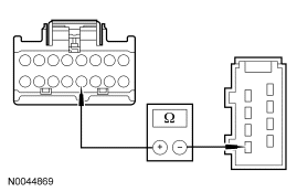
|
Yes GO to AD9. No REPAIR the circuit. REPEAT the self-test. CLEAR the DTCs. If equipped with seat side air bags, DISCONNECT the battery ground cable. DISCONNECT the restraint system diagnostic tool from driver seat side air bag module C327 and CONNECT driver seat side air bag module C327. DISCONNECT the restraint system diagnostic tool from passenger seat side air bag module C313 and CONNECT passenger seat side air bag module C313. REPOWER the SRS. REFER to Section 501-20B. | ||||||||||||
| AD9 CHECK THE BLOWER- CIRCUIT FOR A SHORT TO VOLTAGE | |||||||||||||
|
Yes REPAIR the circuit. REPEAT the self-test. CLEAR the DTCs. If equipped with seat side air bags, DISCONNECT the battery ground cable. DISCONNECT the restraint system diagnostic tool from driver seat side air bag module C327 and CONNECT driver seat side air bag module C327. DISCONNECT the restraint system diagnostic tool from passenger seat side air bag module C313 and CONNECT passenger seat side air bag module C313. REPOWER the SRS. REFER to Section 501-20B. No GO to AD10. | ||||||||||||
| AD10 CHECK THE BLOWER+ CIRCUIT FOR A SHORT TO GROUND | |||||||||||||
|
Yes GO to AD11. No REPAIR the circuit. REPEAT the self-test. CLEAR the DTCs. If equipped with seat side air bags, DISCONNECT the battery ground cable. DISCONNECT the restraint system diagnostic tool from driver seat side air bag module C327 and CONNECT driver seat side air bag module C327. DISCONNECT the restraint system diagnostic tool from passenger seat side air bag module C313 and CONNECT passenger seat side air bag module C313. REPOWER the SRS. REFER to Section 501-20B. | ||||||||||||
| AD11 CHECK THE BLOWER+ AND BLOWER- CIRCUITS FOR AN OPEN | |||||||||||||
|
Yes GO to AD12. No REPAIR the affected circuit. REPEAT the self-test. CLEAR the DTCs. If equipped with seat side air bags, DISCONNECT the battery ground cable. DISCONNECT the restraint system diagnostic tool from driver seat side air bag module C327 and CONNECT driver seat side air bag module C327. DISCONNECT the restraint system diagnostic tool from passenger seat side air bag module C313 and CONNECT passenger seat side air bag module C313. REPOWER the SRS. REFER to Section 501-20B. | ||||||||||||
| AD12 CHECK THE BLOWER+ TO BLOWER- RESISTANCE | |||||||||||||
|
Yes GO to AD13. No INSTALL a new backrest TED. REPEAT the self-test. CLEAR the DTCs. If equipped with seat side air bags, DISCONNECT the battery ground cable. DISCONNECT the restraint system diagnostic tool from driver seat side air bag module C327 and CONNECT driver seat side air bag module C327. DISCONNECT the restraint system diagnostic tool from passenger seat side air bag module C313 and CONNECT passenger seat side air bag module C313. REPOWER the SRS. REFER to Section 501-20B. | ||||||||||||
| AD13 CHECK THE BLOWER SPEED CONTROL RESISTANCE | |||||||||||||
|
Yes GO to AD14. No INSTALL a new backrest TED. REPEAT the self-test. CLEAR the DTCs. If equipped with seat side air bags, DISCONNECT the battery ground cable. DISCONNECT the restraint system diagnostic tool from driver seat side air bag module C327 and CONNECT driver seat side air bag module C327. DISCONNECT the restraint system diagnostic tool from passenger seat side air bag module C313 and CONNECT passenger seat side air bag module C313. REPOWER the SRS. REFER to Section 501-20B. | ||||||||||||
| AD14 CHECK THE TED INSTALLATION AND FOR CRUSHED SEAT BACKREST | |||||||||||||
|
Yes INSTALL a new DCSM and CARRY OUT programmable module installation (PMI). REFER to Climate Controlled Seat Module. REPEAT the self-test. CLEAR the DTCs. If equipped with seat side air bags, DISCONNECT the battery ground cable. DISCONNECT the restraint system diagnostic tool from driver seat side air bag module C327 and CONNECT driver seat side air bag module C327. DISCONNECT the restraint system diagnostic tool from passenger seat side air bag module C313 and CONNECT passenger seat side air bag module C313. REPOWER the SRS. REFER to Section 501-20B. No CORRECTLY install the backrest TED or INSTALL a new seat backrest foam pad and/or climate controlled seat manifold. REPEAT the self-test. CLEAR the DTCs. If equipped with seat side air bags, DISCONNECT the battery ground cable. DISCONNECT the restraint system diagnostic tool from driver seat side air bag module C327 and CONNECT driver seat side air bag module C327. DISCONNECT the restraint system diagnostic tool from passenger seat side air bag module C313 and CONNECT passenger seat side air bag module C313. REPOWER the SRS. REFER to Section 501-20B. |
Pinpoint Test AE: A Single Climate Controlled Seat Is Inoperative/Does Not Operate Correctly
Refer to Wiring Diagrams Cell 119, Climate Controlled Seats for schematic and connector information.
Normal Operation
Both the driver and front passenger climate controlled seats are independently controlled electronically by the dual climate controlled seat module (DCSM) mounted to the bottom of the passenger seat cushion. The climate controlled seat system only operates with the engine running, however, if using a scan tool to command the DCSM, diagnostic testing can be carried out with the ignition switch key ON engine OFF (KOEO). The system receives power from battery junction box (BJB) fuse 12 (30A) feeding battery voltage on circuit SBB12 (GN/RD) into DCSM C3305a pin F. The system also receives power from BJB fuse 11 (30A) feeding battery voltage on circuit SBB11 (BU/RD) into DCSM C3305a pin E. If power is disconnected from either pin E or F of DCSM C3305a with the power connection remaining on the other circuit, both seats will remain operational because the power feed circuits are connected internally in the DCSM. However, if a fault occurs setting a DTC specific to either climate controlled seat, only the affected seat will be disabled by the module and the other will remain operational.
Each driver and front passenger seat cushion is equipped with a thermo-electric device (TED) assembly that includes a seat blower (fan motor, serviced as an assembly with the TED). Similarly, each driver and front passenger seat backrest is also equipped with its own TED assembly with blower. Cabin air is drawn through the blower and distributed to each of the TED modules located in the seat cushion and backrest. The TEDs then heat or cool the air. The air is then directed into the foam pad and manifold where it is distributed along the surface of the cushion and backrest of the seat. Once the system is activated, the DCSM uses a set of flexible algorithms to control the heating/cooling modes and the blower speed dependant on the EATC seat switch settings.
Possible Causes
A single climate controlled seat that does not operate can be caused by:
- wiring, terminals or connectors.
- an MS-CAN fault.
- a faulted electronic automatic temperature control (EATC) module.
- a faulted DCSM.
PINPOINT TEST AE: A SINGLE CLIMATE CONTROLLED SEAT IS INOPERATIVE/DOES NOT OPERATE CORRECTLY
| Test Step | Result / Action to Take |
|---|---|
| AE1 CHECK THE DCSM FOR ON-DEMAND DTCS | |
|
Yes GO to the Dual Climate Controlled Seat Module (DCSM) Diagnostic Trouble Code (DTC) Table. No GO to AE2. |
| AE2 CHECK THE EATC MODULE FOR DTCS | |
|
Yes REFER to Section 412-00 to diagnose the EATC module fault. No GO to AE3. |
| AE3 CHECK OPERATION OF THE DCSM USING THE DIAGNOSTIC TOOL | |
|
Yes GO to AE5. No GO to AE4. |
| AE4 CHECK FOR VOLTAGE TO THE DCSM | |
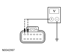
|
Yes INSTALL a new DCSM and CARRY OUT programmable module installation (PMI). REFER to Climate Controlled Seat Module. REPEAT the self-test. CLEAR the DTCs. If equipped with seat side air bags, DISCONNECT the battery ground cable. DISCONNECT the restraint system diagnostic tool from driver seat side air bag module C327 and CONNECT driver seat side air bag module C327. DISCONNECT the restraint system diagnostic tool from passenger seat side air bag module C313 and CONNECT passenger seat side air bag module C313. REPOWER the SRS. REFER to Section 501-20B. No VERIFY battery junction box fuse 12 (30A) and fuse 11 (30A) are OK. If OK, REPAIR the affected circuit. REPEAT the self-test. CLEAR the DTCs. If equipped with seat side air bags, DISCONNECT the battery ground cable. DISCONNECT the restraint system diagnostic tool from driver seat side air bag module C327 and CONNECT driver seat side air bag module C327. DISCONNECT the restraint system diagnostic tool from passenger seat side air bag module C313 and CONNECT passenger seat side air bag module C313. REPOWER the SRS. REFER to Section 501-20B. |
| AE5 MONITOR THE DCSM PIDS | |
|
Yes If the fault is intermittent, CHECK for causes of the intermittent fault. INSPECT the connectors, terminals and wiring. ATTEMPT to recreate the fault by flexing the wire harness and operating the system. CHECK the electrical connectors for corrosion or pushed-out pins. REPAIR and intermittent concerns found. REPEAT the self-test. CLEAR the DTCs. If equipped with seat side air bags, DISCONNECT the battery ground cable. DISCONNECT the restraint system diagnostic tool from driver seat side air bag module C327 and CONNECT driver seat side air bag module C327. DISCONNECT the restraint system diagnostic tool from passenger seat side air bag module C313 and CONNECT passenger seat side air bag module C313. REPOWER the SRS. REFER to Section 501-20B. No GO to AE6. |
| AE6 CHECK THE MS-CAN NETWORK | |
|
Yes INSTALL a new EATC module. REFER to Section 412-01. REPEAT the self-test. CLEAR the DTCs. If equipped with seat side air bags, DISCONNECT the battery ground cable. DISCONNECT the restraint system diagnostic tool from driver seat side air bag module C327 and CONNECT driver seat side air bag module C327. DISCONNECT the restraint system diagnostic tool from passenger seat side air bag module C313 and CONNECT passenger seat side air bag module C313. REPOWER the SRS. REFER to Section 501-20B. No REFER to Section 418-00 to diagnose the MS-CAN concern. REPEAT the self-test. CLEAR the DTCs. If equipped with seat side air bags, DISCONNECT the battery ground cable. DISCONNECT the restraint system diagnostic tool from driver seat side air bag module C327 and CONNECT driver seat side air bag module C327. DISCONNECT the restraint system diagnostic tool from passenger seat side air bag module C313 and CONNECT passenger seat side air bag module C313. REPOWER the SRS. REFER to Section 501-20B. |
Parts & tools for this job For 2007 Ford Fusion
- TOOLTrim removal tool kitSearch: trim removal tool kit
- PARTTouch-up paintSearch: Ford touch up paint
- PARTPanel clip assortmentSearch: Ford panel clips assortment
Links open Amazon search results in a new tab. As an Amazon Associate I earn from qualifying purchases.
Help keep workshop manuals free
workshop-manuals.com provides free online workshop manuals. If they helped you fix your car, please consider sharing or making a small donation to keep the servers running.
Or make a donation:
Support on Ko-fi