
Fusion FWD V6-3.0L (2009)
When the brake pedal is applied, the stoplamp switch routes voltage to the Smart Junction Box (SJB). The voltage is then routed out of the SJB to the
high mounted stoplamp through circuit CLS17 (YE/GY). When the SJB detects the brake pedal applied, the SJB provides voltage to the LH and RH rear
stoplamps through circuit CLS18 (GY/BN) and circuit CLS19 (VT/OG). Ground for the rear stoplamps is provided through circuit GD171 (BK/GY).
Milan, MKZ
When the SJB detects the brake pedal applied, voltage is routed to the stoplamps through circuit CLS17 (YE/GY). Ground for the stoplamps is provided
through circuit GD171 (BK/GY).
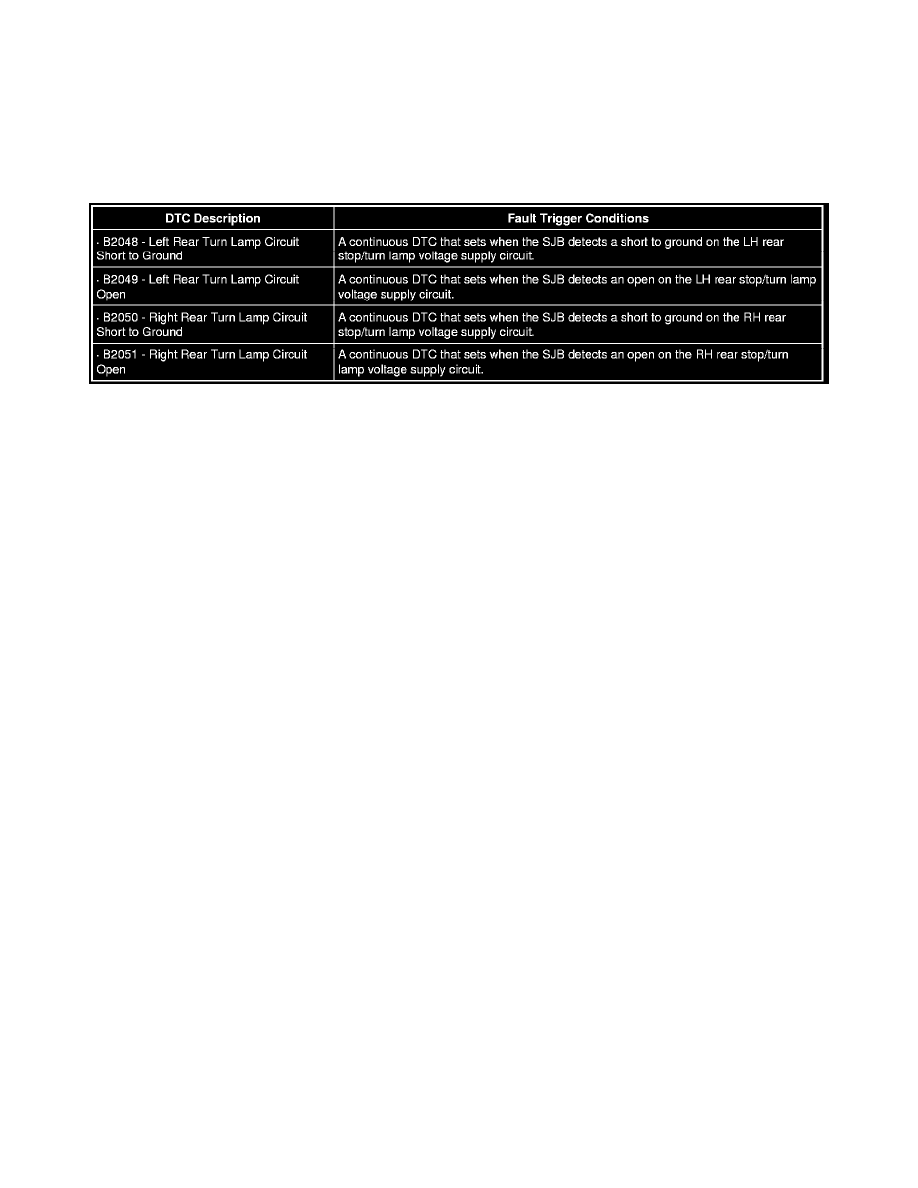
B2048-B2051
This pinpoint test is intended to diagnose the following:
-
Wiring, terminals or connectors
-
Bulb holder
-
High mounted stoplamp
-
Rear lamp assembly
-
SJB
PINPOINT TEST K: ONE OR MORE STOPLAMPS ARE INOPERATIVE
NOTICE: Use the correct probe adapter(s) when making measurements. Failure to use the correct probe adapter(s) may damage the
connector.
NOTE: Failure to disconnect the battery when instructed will result in false resistance readings. Refer to Battery.
-------------------------------------------------
K1 DETERMINE THE INOPERATIVE STOPLAMP
-
Ignition OFF.
-
Apply the brake pedal.
-
Verify which stoplamp is inoperative.
-
Is the high mounted stoplamp inoperative?
Yes
GO to K2.
No
GO to K5.
-------------------------------------------------
K2 CHECK CIRCUIT CLS17 (YE/GY) FOR VOLTAGE
-
Disconnect: High Mounted Stoplamp C475 (Parcel Shelf) or C4111 (Spoiler).
-
While applying the brake pedal, measure the voltage between the high mounted stoplamp C475-1 (parcel shelf) or C4111-1 (spoiler), circuit
CLS17 (YE/GY), harness side and ground.