
Fusion FWD V6-3.0L (2009)
DISCONNECTED
-
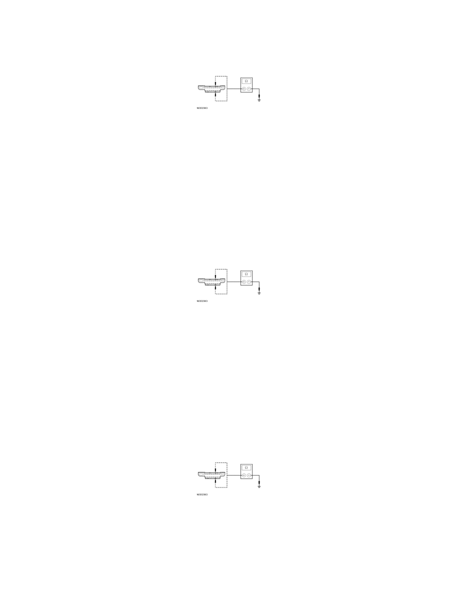
Disconnect: 4X4 Control Module C3253.
-
Measure the resistance between the DLC C251-6, circuit VDB04 (WH/BU), harness side and the DLC C251-14, circuit VDB05 (WH), harness
side.
-
Are the resistances greater than 1,000 ohms?
Yes
CONNECT the negative battery cable. GO to T34.
No
GO to T26.
-------------------------------------------------
T26 CHECK THE HS-CAN (+) AND HS-CAN (-) CIRCUITS FOR A SHORT TO GROUND WITH THE IC DISCONNECTED
-
Disconnect: IC C220.
-
Measure the resistance between the DLC C251-6, circuit VDB04 (WH/BU), harness side and ground; and between the DLC C251-14, circuit
VDB05 (WH), harness side and ground.
-
Are the resistances greater than 1,000 ohms?
Yes
CONNECT the negative battery cable. GO to T35.
No
GO to T27.
-------------------------------------------------
T27 CHECK THE HS-CAN (+) AND HS-CAN (-) CIRCUITS FOR A SHORT TO GROUND WITH THE OCSM DISCONNECTED
-
Disconnect: Occupant Classification System Module (OCSM) C3159.
-
Measure the resistance between the DLC C251-6, circuit VDB04 (WH/BU), harness side and the DLC C251-14, circuit VDB05 (WH), harness
side.
-
Are the resistances greater than 1,000 ohms?
Yes
CONNECT the negative battery cable. GO to T36.
No