| In-vehicle Repair Special Tool(s) | | Flange holding wrench, universal 205-072 (15-030A) | | | Socket, spark plug 303-499 (21-202) | General Equipment Materials Name Specification Lubricant (Never-seeze) ESE-M1244-A Silicon grease A960-M1C171-AA Removal | | -
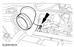
Remove the air cleaner outlet pipe. | | | -
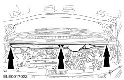
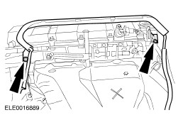
Remove the bulkhead cover. | | | -
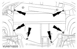
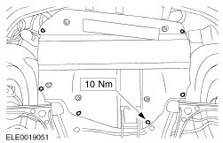
Remove the engine undershield (two nuts and four bolts). | | | -
Remove the spark plug cover. | | | -
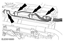
Disconnect the spark plug wires from the spark plugs. | | | -
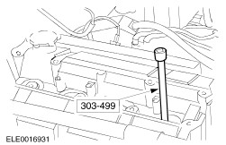
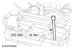
Using the special tool, remove the spark plugs. | | | -
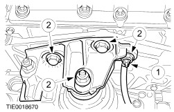
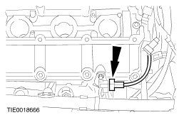
Detach the generator wiring harness support guide from the cylinder head. | | | -
Using a suitable wooden block and a trolley jack support the engine on the oil pan flange. | | | -
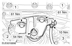
Remove the engine front mounting bracket and disconnect the ground cable from the mounting bracket. - Disconnect the ground cable from the engine front mounting bracket.
- Remove the engine front mounting bracket nut and bolts.
| | | -
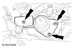
Remove the engine support plate bracket. | | | -
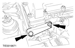
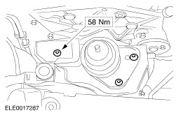
Remove the engine front mounting. | | | -
NOTE:Using a trolley jack and a wooden block raise the engine slightly and push it back until the engine lower support plate retaining bolts are accessible. Remove the engine support plate. | | | -
Disconnect the camshaft position (CMP) sensor electrical connector. | | | -
Remove the upper front cover. | | | -
Rotate the crankshaft in its normal direction until piston No. 1 is at TDC. | | | -
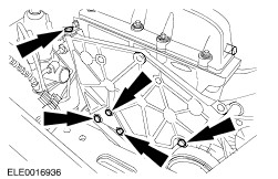
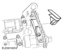
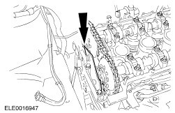
Remove the timing chain upper guide. - Discard the timing chain upper guide.
| | | -
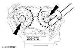
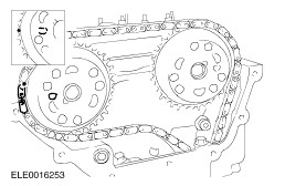
Using the special tool, remove the camshaft sprockets. | | | -
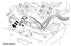
CAUTION:Prevent the retaining washer from dropping into the timing case. NOTE:Using a suitable piece of wire prevent the timing chain from dropping into the timing case. Remove the timing chain tensioner. - Remove the retaining washer.
- Using a M6 x 60 bolt, remove the timing chain tensioner pivot bolt.
| | | -
Remove the timing chain tensioner. - Discard the timing chain tensioner.
| | | -
NOTE:Keep the camshaft bearing caps and bearing shells and the camshafts in order for installation. Remove the camshafts. - Remove the timing chain guide bracket.
- Remove the camshaft bearing caps.
| | | -
NOTE:Keep the hydraulic tappets in order for installation. Remove the hydraulic tappets. | Installation | | -
Rotate the crankshaft in its normal direction until piston No. 1 is 25 mm before top dead center (TDC). | | | -
Coat the hydraulic tappets with engine oil. | | | -
Install the hydraulic tappets in the location from which they were removed. | | | -
Coat the camshaft and the camshaft bearing shells with engine oil. | | | -
NOTE:The intake and exhaust camshafts are marked with two identification rings between the fourth and fifth cams. The exhaust camshaft has larger space between the identification rings. Install the camshafts so that none of the cams are at full lift. | | | -
CAUTION:The crankshaft must not be turned for at least 15 minutes after tightening the camshaft bearing caps. NOTE:The position descriptions of the camshaft bearing caps can be read from the rear. NOTE:Install the camshaft front bearing caps together with the timing chain upper guide bracket. Install the camshaft bearing caps. | | | -
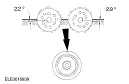
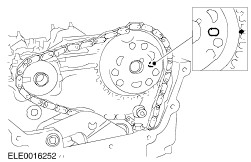
NOTE:Make sure the marking on the crankshaft timing sprocket face vertically upwards. Rotate the camshaft and the crankshaft in its normal direction until piston No. 1 is at TDC. | | | -
CAUTION:Fully or partially released timing chain tensioners must not be used (whether new or used). Check the new timing chain tensioner. | | | -
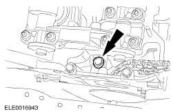
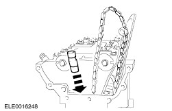
CAUTION:Install a new timing chain tensioner. Install the timing chain tensioner. | | | -
CAUTION:Prevent the retaining washer from dropping into the timing case. Install the timing chain tensioner. - Using a M6 x 60 bolt, install the timing chain tensioner pivot bolt.
- Install the retaining washer.
| | | -
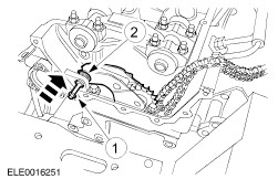
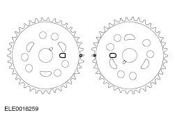
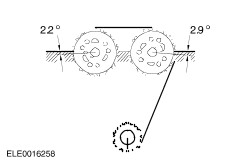
CAUTION:The camshaft sprockets must locate in the slots on the camshaft. NOTE:The timing chain must be taut on the long side. NOTE:The copper links of the timing chain must align with the timing marks on the camshaft sprockets. Install the exhaust camshaft sprocket and the timing chain. - If necessary rotate the camshaft slightly.
| | | -
NOTE:The timing chain may hang down slightly between the camshaft sprockets. NOTE:The copper links of the timing chain must align with the timing marks on the camshaft sprockets. Install the inlet camshaft sprocket. | | | -
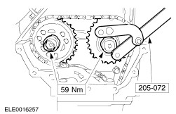
Tighten both camshaft sprocket retaining bolts finger tight. | | | -
Using a suitable brass drift, release the timing chain tensioner. | | | -
Using the special tool, tighten the camshaft sprocket retaining bolts. | | | -
CAUTION:If the timing chain had to be removed while adjusting the valve timing, a new timing chain tensioner must be installed. Rotate the crankshaft in its normal direction until piston No. 2 is at TDC. - Make sure the marks on the camshaft sprockets face one another exactly on level with the upper edge of the cylinder head.
| | | -
CAUTION:If the timing chain had to be removed while adjusting the valve timing, a new timing chain tensioner must be installed. Check the valve timing. - Rotate the crankshaft one revolution in its normal direction and set it to the marks.
| | | -
NOTE:Install a new timing chain upper guide. Install the timing chain upper guide. | | | -
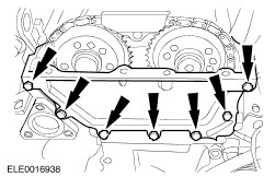
NOTE:Install a new gasket. NOTE:Align the upper edge of the upper cover with the cylinder head mating face (maximum downward offset = 0.13 mm) Install the upper front cover. | | | -
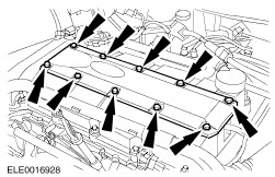
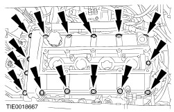
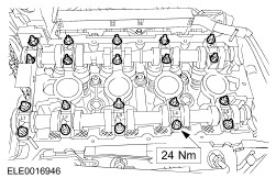
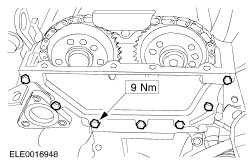
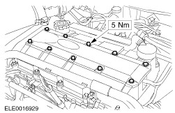
NOTE:Install a new gasket. Install the valve cover (4 nuts and 11 bolts). - Tighten the nuts and bolts in the sequence shown in two stages.
- Stage 1: Tighten nuts and bolts 1 through 15 to 3 Nm.
- Stage 2: Tighten nuts and bolts 1 through 15 to 9 Nm.
| | | -
Connect the CMP sensor electrical connector. | | | -
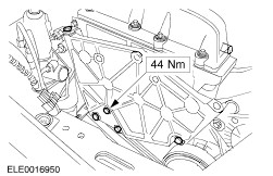
NOTE:Using a trolley jack and a wooden block raise the engine slightly and push it back until the engine lower support plate retaining bolts are accessible. Install the engine support plate. | | | -
Install the engine support plate bracket. | | | -
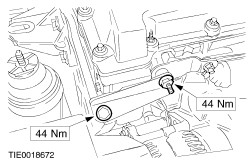
Install the engine front mounting. | | | -
Install the engine front mounting bracket and connect the ground cable to the mounting bracket. - Install the bolts.
- Install the nut.
- Connect the ground cable.
| | | -
Attach the generator wiring harness support guide to the cylinder head. | | | -
Using the special tool, install the spark plugs. | | | -
Using a suitable blunt object to avoid damage to the spark plug connector gasket, coat the inside of the spark plug connector with silicone grease to a depth of 5-10 mm. | | | -
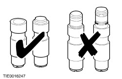
CAUTION:Connect the spark plug wires in line with the spark plugs. Connect the spark plug wires to the spark plugs. | | | -
Install the spark plug cover. | | | -
Install the bulkhead cover. | | | -
Install the air cleaner outlet pipe. | | | -
Install the engine undershield (two nuts and four bolts). | | |