| In-vehicle Repair Special Tool(s) | | Flange holding wrench, universal 205-072 (15-030 A) | | | Angle gauge, bolt tightening 303-174 (21-540) | | | Socket, cylinder head bolt 303-392 (21-167) | | | Remover/Installer, hose clamp 303-397 (24-003) | | | Socket, spark plug 303-499 (21-202) | General Equipment Trolley jack Oil filter strap wrench Materials Name Specification Never-seeze ESE-M1244-A Silicon grease A960-M1C171-AA Engine oil WSS-M2C913-A or WSS-M2C912-A1 Removal | | -
WARNING:Do not smoke or carry lighted tobacco or open flame of any type when working on or near any fuel related components. Highly flammable mixtures are always present and may ignite. Failure to follow these instructions may result in personal injury. | | | -
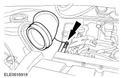
Remove the air cleaner outlet pipe. | | | -
NOTE:The engine undershield remains removed. | | | -
Disconnect the exhaust downpipe from the exhaust manifold. | | | -
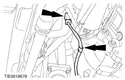
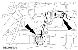
Disconnect the heated oxygen sensor (HO2S) electrical connector. - Detach the HO2S cable from the transaxle.
| | | -
Disconnect the crankshaft position (CKP) sensor and vehicle speed sensor (VSS) electrical connector. | | | -
Disconnect the oil pressure switch electrical connector. | | | -
Remove the spark plug cover. | | | -
Disconnect the electrical connectors and the power supply rail from the fuel injectors. | | | -
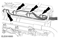
Disconnect the spark plug wires from the spark plugs. | | | -
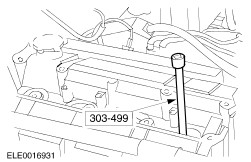
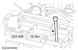
Using the special tool, remove the spark plugs. | | | -
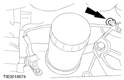
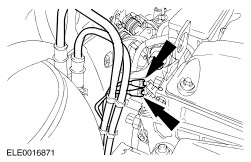
Detach the generator wiring harness support guide from the cylinder head. | | | -
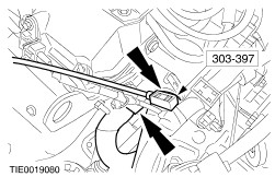
Using the special tool, disconnect the coolant hoses. | | | -
Disconnect the ignition coil electrical connector. | | | -
Disconnect engine cooling fan temperature switch and engine coolant temperature sender unit electrical connectors. | | | -
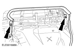
Disconnect the accelerator cable and remove the accelerator cable bracket (three screws). | | | -
Disconnect the vacuum hoses from the intake manifold. | | | -
Using a suitable wooden block and a trolley jack support the engine at the oil pan flange. | | | -
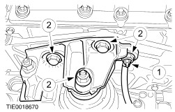
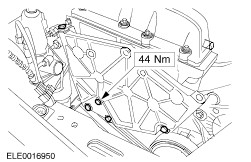
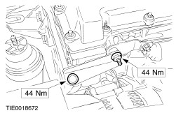
Remove the engine front mounting bracket and disconnect the ground cable from the mounting bracket. - Disconnect the ground cable from the engine front mounting bracket.
- Remove the engine front mounting bracket nuts and bolts.
| | | -
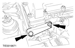
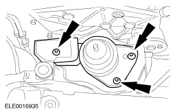
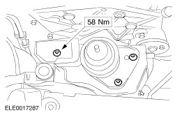
Remove the engine support plate bracket. | | | -
Remove the engine front mounting. | | | -
Remove the exhaust heat shield. | | | -
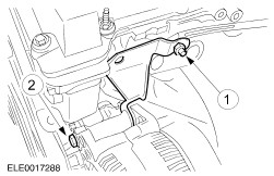
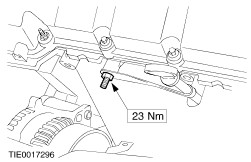
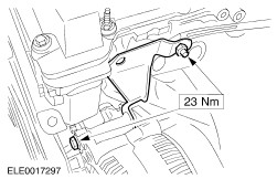
Detach the generator support bracket from the cylinder head. - Remove the generator support bracket retaining nut.
- Loosen the generator upper retaining bolt and allow the generator to swing down.
| | | -
Detach the oil level indicator and tube from the cylinder head. | | | -
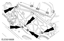
NOTE:Using a suitable trolley jack and a wooden block raise the engine slightly and push it back until the engine lower support plate retaining bolts are accessible. Remove the engine lower support plate retaining bolts together with the engine support plate. | | | -
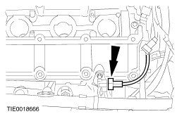
Disconnect the camshaft position (CMP) sensor electrical connector. | | | -
Remove the upper front cover. | | | -
Rotate the crankshaft in its normal direction until piston No. 1 is on top dead center. | | | -
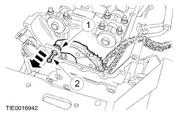
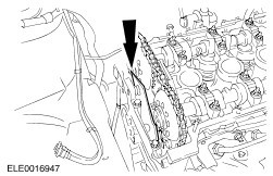
Remove the timing chain upper guide. - Discard the timing chain upper guide.
| | | -
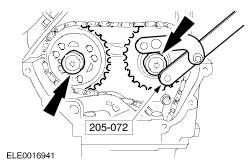
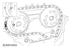
Using the special tool, remove the camshaft sprockets. | | | -
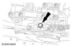
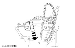
Remove the timing chain guide upper retaining bolt. | | | -
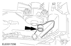
CAUTION:Prevent the retaining washer from dropping into the timing case. NOTE:Using a suitable piece of wire prevent the timing chain from dropping into the timing case. Remove the timing chain tensioner. - Remove the retaining washer.
- Using a M6 x 60 bolt, remove the timing chain tensioner pivot bolt.
| | | -
Remove the timing chain tensioner. - Discard the timing chain tensioner.
| | | -
NOTE:Keep the camshaft bearing caps and shells and the camshafts in order for installation. Remove the inlet camshaft. - Remove the timing chain guide bracket.
- Remove the camshaft bearing caps.
| | | -
CAUTION:The cylinder head must have cooled to below 30°C before undoing the bolts. Remove three cylinder head bolts. | | | -
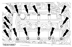
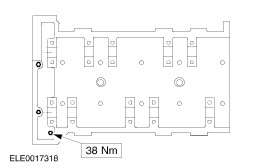
CAUTION:Loosen the bolts in the sequence shown. Using the special tool, remove the cylinder head. - Discard the cylinder head gasket.
| Installation | | -
WARNING:Do not smoke or carry lighted tobacco or open flame of any type when working on or near any fuel related components. Highly flammable mixtures are always present and may ignite. Failure to follow these instructions may result in personal injury. Clean the mating faces of the cylinder head and the cylinder block. | | | -
Turn the engine in its normal direction until piston No. 1 is 25 mm before TDC. | | | -
Only reuse the new style cylinder head bolts if the length is not more than 174.3 mm and the bolt shows no sign of damage. | | | -
NOTE:Install a new cylinder head gasket. Using the special tool, install the cylinder head. - Stage 1: Tighten bolts 1 through 10 to 10 Nm.
- Stage 2: Tighten bolts 1 through 10 to 35 Nm.
- Stage 3: Tighten bolts 1 through 10 to 90 degrees.
- Stage 4: Tighten bolts 1 through 10 to 90 degrees.
| | | -
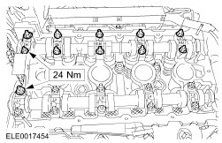
Install three cylinder head bolts. | | | -
Coat the camshaft and the camshaft bearing shells with engine oil. | | | -
CAUTION:The crankshaft must not be turned for at least 15 minutes after tightening the camshaft bearing caps. NOTE:Install the inlet camshaft so that none of the cams is at full lift. NOTE:The position descriptions of the camshaft bearing caps can be read from the rear. NOTE:Install the camshaft front bearing caps together with the timing chain upper guide bracket. Install the inlet camshaft. | | | -
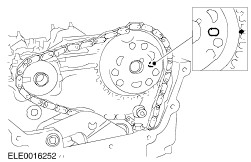
NOTE:Make sure the marking on the crankshaft timing sprocket face vertically upwards. Rotate the camshaft and the crankshaft in its normal direction until piston No. 1 is on TDC. | | | -
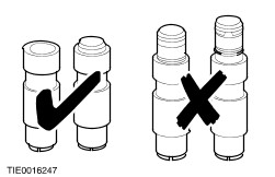
CAUTION:Fully or partially released timing chain tensioner must not be used (whether new or used). Check the new timing chain tensioner. | | | -
CAUTION:Install a new, timing chain tensioner. Install the timing chain tensioner. | | | -
Install the timing chain guide upper retaining bolt. | | | -
CAUTION:Prevent the retaining washer from dropping into the timing case. Install the timing chain tensioner. - Using a M6 x 60 bolt, install the timing chain tensioner pivot bolt.
- Install the retaining washer.
| | | -
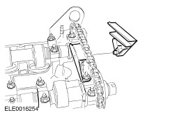
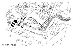
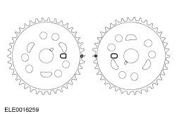
CAUTION:The camshaft sprockets must locate in the slots on the camshaft. NOTE:The copper links of the timing chain must align with the timing marks on the camshaft sprocket. NOTE:The timing chain must be taut on the long side. Install the exhaust camshaft sprocket and the timing chain. - If necessary rotate the camshaft slightly.
| | | -
NOTE:The copper links of the timing chain must align with the timing marks on the camshaft sprockets. NOTE:The timing chain may hang down slightly between the camshaft sprockets. Install the inlet camshaft sprocket and the timing chain. | | | -
Tighten both camshaft sprocket retaining bolts finger tight. | | | -
Using a suitable brass drift, release the timing chain tensioner. | | | -
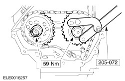
Using the special tool, tighten the camshaft sprocket retaining bolts. | | | -
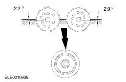
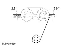
CAUTION:If the timing chain had to be removed while adjusting the valve timing, a new timing chain tensioner must be installed. Rotate the crankshaft in its normal direction until piston No. 2 is on TDC. - Make sure the marks on the camshaft sprockets face one another exactly on level with the upper edge of the cylinder head.
| | | -
CAUTION:If the timing chain had to be removed while adjusting the valve timing, a new timing chain tensioner must be installed. Check the valve timing. - Rotate the crankshaft one revolution in its normal direction and set it to the marks.
| | | -
NOTE:Install a new timing chain upper guide. Install the timing chain upper guide. | | | -
NOTE:Install a new gasket. NOTE:Align the upper edge of the upper front cover with the cylinder head mating face (maximum downward offset = 0.13 mm) Install the upper front cover. | | | -
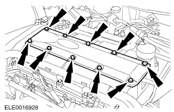
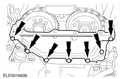
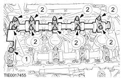
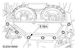
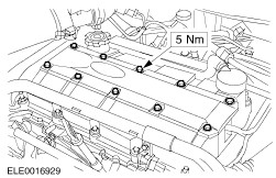
NOTE:Install a new gasket. Install the valve cover (4 nuts and 11 bolts). - Tighten the nuts and bolts in the sequence shown in two stages.
- Stage 1: Tighten nuts and bolts 1 through 15 to 3 Nm.
- Stage 2: Tighten nuts and bolts 1 through 15 to 9 Nm.
| | | -
Connect the CMP sensor electrical connector. | | | -
Attach the oil level indicator and tube to the cylinder head. | | | -
Install the exhaust heat shield. | | | -
NOTE:Using a trolley jack and a wooden block raise the engine slightly and push it back until the engine lower support plate retaining bolts are accessible. NOTE:Install the engine support plate together with the engine lower support plate retaining bolts. Install the engine support plate. | | | -
Install the engine support plate bracket. | | | -
Attach the generator support bracket to the cylinder head. | | | -
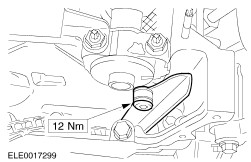
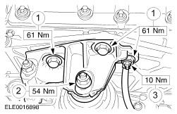
Install the engine front mounting. | | | -
Install the engine front mounting bracket and connect the ground cable to the mounting bracket. - Install the nut and the bolts.
- Install the nut.
- Connect the ground cable.
| | | -
Connect the vacuum hoses to the intake manifold. | | | -
Install the accelerator cable bracket (three screws) and connect the accelerator cable. | | | -
Connect the ignition coil electrical connector. | | | -
Connect engine cooling fan temperature switch and engine coolant temperature (ECT) sensor electrical connectors. | | | -
Using the special tool, connect the coolant hoses. | | | -
Attach the generator wiring harness support guide to the cylinder head. | | | -
Apply grease on the spark plug threads. | | | -
Using the special tool, install the spark plugs. | | | -
Using a suitable blunt object to avoid damage to the spark plug connector gasket, coat the inside of the spark plug connector with silicone grease to a depth of 5-10 mm. | | | -
CAUTION:Connect the spark plug wires in line with the spark plugs. Connect the spark plug wires to the spark plugs. | | | -
Connect the electrical connectors and the power supply rail to the fuel injectors. | | | -
Install the spark plug cover. | | | -
Connect the oil pressure switch electrical connector. | | | -
Connect the CKP sensor and VSS electrical connector. | | | -
Connect the HO2S electrical connector. - Attach the HO2S cable to the transaxle.
| | | -
NOTE:Install a new gasket. Install the exhaust downpipe. | | | -
Install the air cleaner outlet pipe. body. | | | -
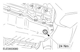
Drain the engine oil. - Discard the oil drain plug washer.
| | | -
NOTE:Install a new oil drain plug washer. Install the oil drain plug. | | | -
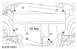
Install the engine undershield (two nuts and four bolts). | | |