| Disassembly and Assembly of Subassemblies Special Tool(s) | | Compressor, Valve Spring 303-060 (21-024) | | | Adapter for 303-060 303-060-07 (21-024-07) | | | Adapter for 303-060 303-060-09 (21-024-08) | | | Installer, Valve Stem Collets 303-362 (21-156) | | | Adapter, Air Supply (cylinder head) 303-363 (21-157) | | | Pliers, Valve Stem Oil Seal 303-508 (21-211) | Materials Name Specification Valve stem mounting sleeve Engine oil ACEA A3/B3 Disassembly | | -
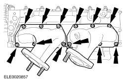
Remove the secondary air injection valve. | | | -
Remove the exhaust manifold. | | | -
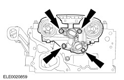
Remove the camshaft control housing. | | | -
NOTE:Keep the camshaft bearing caps and the camshafts in order for installation. Remove the inlet camshaft. | | | -
NOTE:Keep the camshaft bearing caps and the camshafts in order for installation. Remove the exhaust camshaft. | | | -
NOTE:Keep the roller cam follower in order for installation. Remove the roller cam follower. | | | -
NOTE:Keep the hydraulic lash adjusters in order for installation. Remove the hydraulic lash adjusters. | | | -
CAUTION:Do not damage the valve stem when pressing down the valve spring retainer. Using the special tools, remove the valve collets. | | | -
Remove the valve spring and the valve spring retainer. | | | -
Using the special tool, remove the valve stem seal. | Assembly | | -
Push the valve stem mounting sleeve over the valve collet groove (valve shown removed for clarity). | | | -
NOTE:Install a new valve stem seal. Using the special tool, install the valve stem seal. | | | -
Remove the valve stem mounting sleeve. | | | -
Install the valve spring and the valve spring retainer. | | | -
CAUTION:Do not damage the valve stem when pressing down the valve spring retainer. Using the special tools, install the valve collets. | | | -
Repeat the previous steps to remove and install the other valve seals. | | | -
Install the hydraulic lash adjusters. - Coat the hydraulic lash adjusters with engine oil.
| | | -
NOTE:Make sure that the roller cam followers are clipped onto the hydraulic lash adjusters by the retaining clips. NOTE:Coat the roller cam follower with engine oil. Install the roller cam follower. | | | -
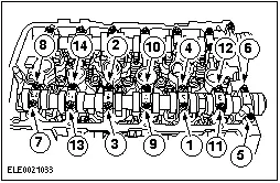
NOTE:The inlet and exhaust camshafts are marked with identification number between the cams of cylinder 4 and 5 Identify the camshafts. - Exhaust camshaft: 022 101
| | | -
Coat the camshaft and the camshaft bearing caps with engine oil. | | | -
NOTE:Install the camshaft so that the cams of cylinder No. 1 show to the top. Install the exhaust camshaft. | | | -
NOTE:Install the camshaft so that the cams of cylinder No. 1 show to the top. Install the inlet camshaft. | | | -
Install the camshaft control housing. | | | -
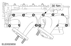
NOTE:Install new gaskets. Install the exhaust manifold. | | | -
NOTE:Install a new gasket. Install the secondary air injection valve. | |