| Disassembly Special Tool(s) | | Socket, Splined Head 303-042 (21-012) | | | Remover, Crankshaft Oil Seal 303-293 (21-143) | | | Remover/Installer, Cooling Hose Clamp 303-397 (24-003) | | | Mounting Stand 303-435 (21-187) | | | Mounting Bracket for 303-435 303-435-06 (21-031 B) | | | Mounting Plate for 303-435 303-435-11 (21-146 C) | | | Socket, Flywheel Bolt 303-502 (21-205) | | | Locking Tool, Crankshaft Vibration Damper 303-503 (21-206) | | | Pliers, Spark Plug Connector 303-622 (21-226) | General Equipment Disassembly | | -
Using the special tools, mount the engine on the stand. | | | -
NOTE:Install a new oil drain plug washer. Install the oil drain plug. | | | -
Detach the electronic ignition (EI) coil. - Detach the wiring loom from the bracket.
| | | -
Remove the positive crankcase ventilation hose. | | | -
Remove the throttle body air intake resonator. - Detach the vacuum line.
- Disconnect the intake air temperature electrical connector.
- Remove the throttle body air intake resonator retaining bolts.
| | | -
Disconnect the throttle position (TP) sensor electrical connector. | | | -
Disconnect the low pressure line from the intake manifold. | | | -
Disconnect the ground lead from the throttle body (one bolt). | | | -
Remove the accessory drive belt tensioner. | | | -
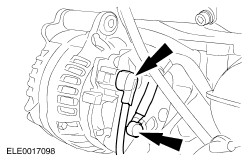
Disconnect the generator electrical connectors. | | | -
Remove the generator bracket. | | | -
Remove the oil level indicator and tube. - Detach the crankshaft position (CKP) sensor electrical connector from the oil level indicator tube.
| | | -
Remove the intake manifold upper retaining bolts (three bolts). | | | -
Disconnect the intake manifold runner control vacuum line. | | | -
Remove the intake manifold. | | | -
Disconnect the oil pressure switch electrical connector. | | | -
Remove the left-hand knock sensor (KS). | | | -
Disconnect the oil level and temperature sensor electrical connector. - Detach the wiring loom from the retaining bracket.
| | | -
Remove the right-hand knock sensor (KS). | | | -
Remove the wiring loom bracket. | | | -
Detach the wiring loom from the retaining bracket. | | | -
Disconnect the fuel injector electrical connectors. | | | -
Disconnect the vacuum line from the fuel pressure regulator. | | | -
Disconnect the engine coolant temperature (ECT) sensor electrical connector. | | | -
Disconnect the engine cooling fan temperature switch electrical connector. | | | -
NOTE:Mark the positions of the electrical connectors. Disconnect the camshaft position (CMP) sensor electrical connectors and the intake and exhaust camshaft control valve electrical connectors. | | | -
Detach the secondary air injection pipe from the secondary air injection (AIR) valve. | | | -
Remove the wiring loom lower bracket. | | | -
Remove the wiring loom upper bracket. - Detach the wiring loom from the upper bracket.
| | | -
Remove the wiring loom and the air injection pipe. | | | -
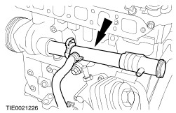
Remove the thermostat housing. | | | -
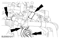
Using the special tool, disconnect the coolant hose from the coolant tube. | | | -
Remove the coolant tube. - Discard the O-ring seals.
| | | -
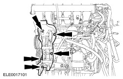
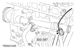
Remove the oil filter housing. - Using the special tool, disconnect the coolant hose.
- Remove the oil filter housing retaining bolts.
- Discard the O-ring seals.
| | | -
Remove the timing chain tensioner. | | | -
Remove the timing chain upper cover. | | | -
Remove the timing chain upper guide. | | | -
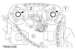
CAUTION:Mark the front face of the timing chain with a suitable marker to aid installation. Do not use a punch. NOTE:Hold the camshafts by the hexagon with an open ended wrench to stop them from turning. Remove both camshafts swivelling adjusters. - Remove the exhaust camshaft swivelling adjuster.
- Remove the inlet camshaft swivelling adjuster.
- Remove the upper timing chain.
| | | -
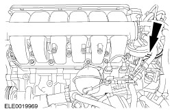
NOTE:Loosen the bolts in the sequence shown. Remove the cylinder head. | | | -
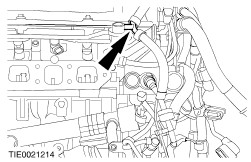
Using the special tool, remove the oil retaining valve. | | | -
Install the special tool, prevent the crankshaft from turning. | | | -
Remove the clutch disc and pressure plate. | | | -
Remove the crankshaft pulley bolt. - Remove the crankshaft pulley.
| | | -
Remove the crankshaft front oil seal. | | | -
Remove the crankshaft front oil seal carrier. | | | -
Remove the crankshaft rear oil seal. | | | -
Remove the oil pan retaining bolts | | | -
CAUTION:Remove the oil pan by pulling it downwards to prevent oil deposits or abraded particles from entering the engine. Using the special tool, remove the oil pan. - Slide the special tool around the profile of the oil pan.
| | | -
Remove the timing chain lower cover. | | | -
Remove the lower timing chain tensioner. | | | -
Remove the intermediate shaft sprocket retaining bolt. | | | -
CAUTION:Mark the front face of the timing chain with a suitable marker to aid installation. Do not use a punch. Remove the intermediate shaft sprockets together with the timing chain and the timing chain lower guide. | | | -
Remove the intermediate shaft. | | | -
Remove the oil pump drive. | | | -
NOTE:Mark the connecting rod bearing caps and the connecting rod in accordance to the cylinder to which they belong and keep them in order for installation. NOTE:Do not damage the cylinder bores. Remove connecting rod bearing caps and remove the pistons. | | | -
NOTE:Keep the crankshaft bearing caps, bearing shells and half thrust-washers in order for installation. NOTE:Main bearing No. 5 is fitted with thrust half washers. Remove the crankshaft bearing caps and the crankshaft. | | | -
Using a suitable 4 mm pin punch, remove the piston cooling oil spray nozzles from number two and number seven main bearing seats. | | |