| In-vehicle Repair Special Tool(s) | | Universal Flange Holding Wrench 205-072 (15-030A) | | | Socket, Cylinder Head Bolt 303-033 (21-002) | | | Remover, Crankshaft Vibration Damper 303-338 (21-153B) | | | Remover/Installer, Hose Clamp 303-397 (24-003) | | | Wrench, Timing Belt Tensioner 303-1053 | | | Locking tool, Timing Belt Tensioner 303-1054 | | | Holding Tool, Timing Belt Hydraulic Tensioner 310-084 (23-058) | | | Locking Tool, Crankshaft 310-085 (23-059) | General Equipment Three M8 x 70 mm bolts Trolley jack Straight edge Feeler blade 4 mm drill bit 6 mm drill bit Materials Name Specification Engine oil WSS-M2C917-A Removal All Vehicles | | -
WARNING:Do not smoke or carry lighted tobacco or open flame of any type when working on or near any fuel related components. Highly flammable vapors are always present and may ignite. Failure to follow these instructions may result in personal injury. NOTE:Do not install the engine undershield. Drain the cooling system.
For additional information, refer to: Cooling System Draining, Filling and Bleeding (303-03B Engine Cooling - 1.9L Diesel, General Procedures).
| | | -
Remove the battery.
For additional information, refer to: Battery (414-01 Battery, Mounting and Cables, Removal and Installation).
| | | -
Remove the air cleaner.
For additional information, refer to: Air Cleaner - 1.9L Diesel (303-12 Intake Air Distribution and Filtering, Removal and Installation).
| | | -
Remove the engine noise reduction material. | | | -
Using the special tool, disconnect the air cleaner outlet pipe from the turbocharger intake pipe. | | | -
Remove the accessory drive belt.
For additional information, refer to: Accessory Drive Belt - 1.9L Diesel (303-05 Accessory Drive, Removal and Installation).
| | | -
Remove the bulkhead cover. | | | -
Disconnect the engine coolant level sensor electrical connector. | | | -
Remove the battery side cover. | | | -
Detach the fuel filter bracket from the battery tray. | | | -
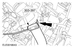
Using the special tool, disconnect the charge air cooler pipe. | | | -
Disconnect the manifold absolute pressure (MAP) sensor and the intake air temperature (IAT) sensor electrical connector and remove the intake air pipe. | | | -
Using the special tool, disconnect the coolant hoses from the coolant outlet housing. | | | -
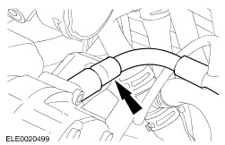
Using the special tool, disconnect the coolant bleeding hose from the T-piece. | | | -
Disconnect the fuel temperature sensor electrical connector. | | | -
Disconnect the fuel lines from the fuel pump and close off the fuel lines with suitable plugs. | | | -
Disconnect the electrical connectors from the unit injectors. | | | -
Disconnect the brake booster vacuum line from the vacuum pump. | | | -
Disconnect the vacuum hose from the intake pipe plate vacuum servo. | | | -
Disconnect the vacuum hose from the exhaust gas recirculation (EGR) valve. | | | -
Disconnect the power supply rail from the glow plugs. | | | -
Disconnect the camshaft position (CMP) sensor electrical connector and detach it from the retaining bracket. | | | -
Disconnect the vacuum hoses. | | | -
Disconnect the turbocharger intake pipe from the intake manifold and the positive crankcase ventilation (PCV) hose. | | | -
Disconnect the engine coolant temperature (ECT) electrical connector. | | | -
Raise and support the vehicle. For additional information, refer to: (100-02 Jacking and Lifting) Jacking (Description and Operation), Lifting (Description and Operation). | | | -
Using the special tool, disconnect the charge air cooler pipe. | | | -
Remove the turbocharger intake pipe. | | | -
Detach the charge air cooler pipe bracket from the oil pan. | | | -
Remove the charge air cooler pipe from the turbocharger. | | | -
Disconnect the turbocharger oil return tube from the engine cylinder block. | | | -
Remove the turbocharger bracket retaining bolt. | | | -
CAUTION:Excessive bending of the exhaust flexible pipe may cause damage resulting in failure. Support the exhaust flexible pipe with a support wrap. | | | -
Detach the exhaust flexible pipe from the turbocharger. - Discard the gasket and the nuts.
| | | -
Detach the exhaust flexible pipe from the catalytic converter and detach the exhaust flexible pipe from the exhaust hanger insulators. - Discard the gasket and the nuts.
| | | -
Using the special tool, disconnect the coolant hose from the cylinder head. | | | -
Detach the power steering line from the engine. | | | -
Remove the crankshaft pulley. | | | -
Remove the lower timing belt cover. | | | -
NOTE:The engine support plate lower retaining bolt will be removed with the engine support plate. Loosen the engine support plate lower retaining bolt. | | | -
Using a suitable wooden block and a trolley jack, support the engine. | | | -
Remove the engine front mount bracket. | | | -
Remove the engine front mount. | | | -
Remove the engine support plate. | | | -
Remove the engine support. | | | -
Remove the accessory drive belt tensioner. | | | -
Remove the timing belt upper cover. | | | -
Remove the timing belt center cover. | Vehicles with hydraulic timing belt tensioner | | -
Slacken the timing belt. - Loosen the timing belt tensioner retaining nut.
- Using the special tool, rotate the timing belt tensioner cam counterclockwise until the special tool can be inserted.
- Using the special tool, slacken the timing belt by turning the timing belt tensioner cam clockwise.
| | | -
Remove the timing belt tensioner. | | | -
NOTE:Remove the timing belt from the coolant pump pulley first. Remove the timing belt. | | | -
Remove the timing belt tensioner pulley. | Vehicles with mechanical timing belt tensioner | | -
Using the special tools, loosen the camshaft pulley retaining bolts until the camshaft pulley is free to move in the elongated bolt holes. | | | -
Slacken the timing belt. - Loosen the timing belt tensioner retaining nut.
- Using the special tool, rotate the timing belt tensioner cam counterclockwise until the special tool can be inserted.
- Using the special tool, rotate the timing belt tensioner cam clockwise until its stop and tighten the retaining nut finger tight.
| | | -
NOTE:Remove the timing belt from the coolant pump pulley first. Remove the timing belt. | | | -
Remove the timing belt tensioner. | All vehicles | | -
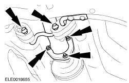
Remove the valve cover (13 bolts). | | | -
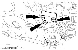
Disconnect the turbocharger oil supply line from the turbocharger. - Detach the turbocharger oil supply line from the intake manifold.
| | | -
Disconnect the turbocharger oil supply line from the oil filter housing (engine shown removed for clarity). - Detach the turbocharger supply line from the cylinder block.
| | | -
Using the special tool, remove the camshaft pulley. - Loosen the camshaft pulley center bolt by two turns.
- Remove the camshaft pulley.
| | | -
Remove the timing belt rear cover and the timing belt tensioner stud. | | | -
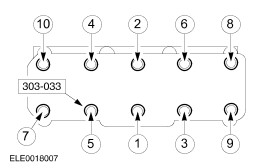
NOTE:Loosen the cylinder head bolts in the sequence shown. Using the special tool, remove the cylinder head. - Discard the cylinder head bolts and the cylinder head gasket.
| Installation All Vehicles | | -
Select the cylinder head gasket.
For additional information, refer to: Specifications (303-01D Engine - 1.9L Diesel, Specifications).
| | | -
Rotate the crankshaft in its normal direction until piston No. 1 is 90 degrees before TDC. | | | -
CAUTION:Make sure that the cylinder head bolt washers are installed. NOTE:Install a new cylinder head gasket and new cylinder head bolts. Using the special tool, install the cylinder head. - Tighten the bolts in the sequence shown in four stages.
- Stage 1: Tighten bolts 1 through 10 to 40 Nm.
- Stage 1: Tighten bolts 1 through 10 to 60 Nm.
- Stage 3: Tighten bolts 1 through 10 to 90 degrees.
- Stage 4: Tighten bolts 1 through 10 to 90 degrees.
| | | -
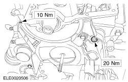
Install the timing belt tensioner stud and the timing belt rear cover. | | | -
NOTE:Do not tighten the camshaft pulley retaining bolts at this stage. Using the special tool, install the camshaft pulley hub together with the camshaft pulley and tighten the camshaft pulley hub. | | | -
NOTE:Do not tighten the oil supply line at this stage. Connect the turbocharger oil supply line to the oil filter housing (engine shown removed for clarity). - Attach the turbocharger oil supply line to the cylinder block.
| | | -
Connect the turbocharger oil supply line to the turbocharger. - Attach the turbocharger oil supply line to the intake manifold.
| | | -
Tighten the turbocharger oil supply line (engine shown removed for clarity). | | | -
NOTE:Install the valve cover within five minutes of applying the silicon sealer. Apply a 5 mm diameter point to the front and rear camshaft bearing caps. | | | -
NOTE:Inspect the valve cover gasket for damage. Install a new valve cover gasket if damaged. Install the valve cover and tighten the bolts in the sequence shown. | | | -
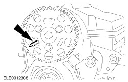
WARNING:Wrap the flutes of the drill bit with a suitable tape. Failure to follow this instruction may result in personal injury. Rotate the camshaft in its normal direction of rotation and insert a 6 mm drill bit through the hole in the cylinder head. | | | -
Rotate the camshaft pulley clockwise until it stops at the 6 mm drill bit. | | | -
NOTE:Make sure the marks on the camshaft timing pulley and on the special tool face one another exactly. The special tool must be installed from the front to the sprocket and engage in the bore of the crankshaft front seal carrier mating face. Install the special tool. | Vehicles with hydraulic timing belt tensioner | | -
NOTE:Do not tighten the nut at this stage. Install the timing belt tensioner pulley. | | | -
NOTE:Install a new timing belt. Install the timing belt beginning with the camshaft pulley followed by timing belt tensioner, crankshaft timing pulley and water pump pulley. | | | -
Install the timing belt tensioner. | | | -
Tension the timing belt. - Using the special tools rotate the timing belt tensioner cam counterclockwise and remove the special tool.
| | | -
WARNING:Wrap the flutes of the drill bit with a suitable tape. Failure to follow this instruction may result in personal injury. NOTE:Install a new 4 mm drill bit. Adjust the timing belt tensioner. - Using the special tool, rotate the timing belt tensioner cam clockwise until the drill bit can be inserted.
- Tighten the timing belt tensioner retaining nut in two stages.
| Vehicles with mechanical timing belt tensioner | | -
Rotate the camshaft pulley counterclockwise until its stop. | | | -
NOTE:Install a new timing belt. Install the timing belt beginning with the camshaft pulley followed by timing belt tensioner, crankshaft timing pulley and water pump pulley. | | | -
Insert the timing belt tensioner in the timing belt rear cover. | | | -
Loosen the timing belt tensioner retaining nut. - Using the special tools, rotate the timing belt tensioner cam counterclockwise and remove the special tool.
| | | -
Adjust the timing belt tensioner. - Using the special tool, rotate the timing belt tensioner cam clockwise until the arrow points at the mark.
- Tighten the timing belt tensioner retaining nut in two stages.
| All vehicles | | -
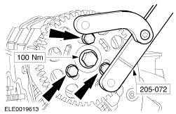
Using the special tool, tighten the camshaft pulley retaining bolts. | | | -
Remove the 6 mm drill bit. | | | -
Check the valve timing. - Rotate the crankshaft two revolutions in its normal direction and set piston No. 1 at TDC.
| | | -
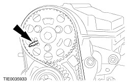
NOTE:Make sure the marks on the crankshaft timing pulley and on the special tool face one another exactly. The special tool must be installed from the front to the sprocket and engage in the bore of the crankshaft front seal carrier mating face. Install the special tool. | Vehicles with hydraulic timing belt tensioner | | -
WARNING:Wrap the flutes of the drill bit with a suitable tape. Failure to follow this instruction my result in personal injury. Check the timing belt tensioner setting by inserting a 4 mm drill bit. | Vehicles with mechanical timing belt tensioner | | -
Check that the arrow points at the mark. | All vehicles | | -
WARNING:Wrap the flutes of the drill bit with a suitable tape. Failure to follow this instruction my result in personal injury. Insert a 6 mm drill bit through the hole in the camshaft pulley. If the drill bit can not be inserted, loosen the camshaft pulley retaining bolts, insert the drill bit and tighten the camshaft pulley retaining bolts. | | | -
Install the timing belt center cover. | | | -
Install the timing belt upper cover. | | | -
Install the accessory drive belt tensioner. | | | -
NOTE:Do not tighten the engine support retaining bolt at this stage. Install the engine support. | | | -
NOTE:Install the engine lower support plate retaining bolts together with the engine support plate. Install the engine support plate. | | | -
Install the engine front mount. | | | -
Install the engine front mount bracket. | | | -
Raise and support the vehicle. For additional information, refer to: (100-02 Jacking and Lifting) Jacking (Description and Operation), Lifting (Description and Operation). | | | -
Tighten the engine support plate retaining bolt. | | | -
Install the lower timing belt cover. | | | -
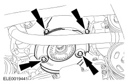
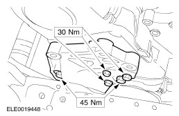
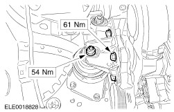
Install the crankshaft pulley. - Tighten the bolts in two stages.
| | | -
Attach the power steering line to the engine. | | | -
NOTE:Install a new gasket and new self-locking nuts. Attach the exhaust flexible pipe to the catalytic converter and the exhaust hanger insulators. | | | -
NOTE:Install a new gasket and new self-locking nuts. Attach the exhaust flexible pipe to the turbocharger. | | | -
Remove the exhaust flexible pipe support wrap. | | | -
Install the turbocharger bracket retaining bolt. | | | -
Connect the turbocharger oil return tube to the engine block. | | | -
Install the charge air cooler pipe to the turbocharger. | | | -
Attach the charge air cooler pipe to the bracket. | | | -
NOTE:Inspect the O-ring seal for damage. Install a new O-ring seal if damaged. Install the turbocharger intake pipe. | | | -
Using the special tool, connect the charge air cooler pipe. | | | -
Connect the engine coolant temperature (ECT) sensor electrical connector. | | | -
Connect the turbocharger intake pipe to the intake manifold and the positive crankcase ventilation (PCV) hose to the valve cover. | | | -
Connect the vacuum hoses. | | | -
Connect the camshaft position (CMP) sensor electrical connector and attach the CMP sensor electrical connector to the retaining bracket. | | | -
Connect the power supply rail to the glow plugs. | | | -
Connect the vacuum hose to the exhaust gas recirculation (EGR) valve. | | | -
Connect the vacuum hose to the intake pipe plate vacuum servo. | | | -
Connect the brake booster vacuum line to the vacuum pump. | | | -
Connect the electrical connectors to the unit injectors. | | | -
Connect the fuel lines to the fuel pump. | | | -
Connect the fuel temperature sensor electrical connector. | | | -
Using the special tool, connect the coolant bleeding hose to the T piece. | | | -
Connect the coolant hose to the coolant outlet housing. | | | -
NOTE:Inspect the O-ring seal for damage. Install a new O-ring seal if damaged. Install the charge air cooler pipe and connect the manifold absolute pressure (MAP) sensor and intake air temperature (IAT) sensor electrical connector. | | | -
Using the special tool, connect the charge air cooler pipe. | | | -
Attach the fuel filter bracket to the battery tray. | | | -
Install the battery side cover. | | | -
Connect the engine coolant level sensor electrical connector. | | | -
Install the bulkhead cover. | | | -
Install the accessory drive belt.
For additional information, refer to: Accessory Drive Belt - 1.9L Diesel (303-05 Accessory Drive, Removal and Installation).
| | | -
Using the special tool, connect the air cleaner outlet pipe to the turbocharger intake pipe. | | | -
Install the engine noise reduction material. | | | -
Install the engine cover. | | | -
Install the air cleaner.
For additional information, refer to: Air Cleaner - 1.9L Diesel (303-12 Intake Air Distribution and Filtering, Removal and Installation).
| | | -
Install the battery.
For additional information, refer to: Battery (414-01 Battery, Mounting and Cables, Removal and Installation).
| | | -
Fill and bleed the engine cooling system.
For additional information, refer to: Cooling System Draining, Filling and Bleeding (303-03B Engine Cooling - 1.9L Diesel, General Procedures).
| | | -
Install the engine undershield. | |