| Removal Special Tool(s) | | Remover/Installer, Hose clamp 303-397 (24-003) | | | Splined Bit Set 303-702 | General Equipment Assembly stand Engine hoist 5 mm drill bit Retaining Straps All vehicles | | -
WARNING:Do not smoke or carry lighted tobacco or open flame of any type when working on or near any fuel related components. Highly flammable mixtures are always present and may ignite. Failure to follow these instructions may result in personal injury. | | | -
Disconnect the battery positive cable from the battery terminal clamp. | | | -
Remove the engine noise reduction material. | | | -
NOTE:Do not install the engine undershield. | | | -
Disconnect the engine coolant level sensor (ECL) electrical connector. | | | -
Disconnect the engine wiring harness and detach it from the battery tray. | | | -
Disconnect the powertrain control module (PCM) electrical connector. | | | -
Remove the battery side cover. | | | -
Detach the wiring harness rail from the battery tray. | | | -
Disconnect the brake booster vacuum line. | Vehicles with 115 PS diesel engine | | -
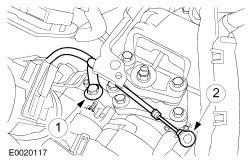
Using the special tool, disconnect the coolant hoses from the coolant expansion tank. | | | -
CAUTION:Cap the fuel lines to prevent fluid loss or dirt ingress. Using the special tool, disconnect the fuel lines from the fuel filter and detach the filter. | | | -
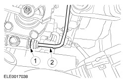
Using the special tool, disconnect the coolant hose from the coolant distribution tube. | | | -
Remove the retaining clip and disconnect the coolant hose from the coolant distribution tube. | Vehicles with 130 PS diesel engine | | -
Using the special tool, disconnect the coolant hoses from the coolant expansion tank. | | | -
Disconnect the vacuum line from the vacuum valve. | | | -
CAUTION:Cap the fuel lines to prevent fluid loss or dirt ingress. Using the special tool, disconnect the fuel lines from the fuel pump and the fuel cooler. | Vehicles with automatic transaxle | | -
Using the special tool, disconnect the coolant hose from the transaxle fluid cooler. | | | -
Detach the selector lever cable from the transaxle. - Unclip the selector lever cable.
- Detach the selector lever cable bracket from the transaxle.
| | | -
Detach the selector lever cable from the bracket. | Vehicles with manual transaxle | | -
Remove the gearshift lever knob and the gearshift lever boot. | | | -
Using a 5 mm drill bit, lock the gearshift lever. | | | -
Detach the gearshift and selector cable from the transaxle. - Detach the cables, turning the abutment collar clockwise.
- Pull the locking mechanism backwards and turn it counterclockwise to lock in position.
| | | -
CAUTION:If brake fluid is spilt on the paintwork, the affected area must be immediately washed down with cold water. CAUTION:Cap the clutch slave cylinder supply line to prevent fluid loss or dirt ingress. Disconnect the clutch slave cylinder pressure line from the transaxle. - Remove the spring clip.
- Disconnect the quick release coupling.
| | | -
Detach the clutch slave cylinder pressure line from the selector cable bracket. | | | -
Disconnect the reversing lamp switch electrical connector. | All vehicles | | -
Disconnect the generator positive cable from the battery junction box. | | | -
Using the special tool, disconnect the air intake pipe and secure it to the air conditioning line. | | | -
Disconnect the vacuum hose from the vacuum reservoir. | | | -
Using the special tool, disconnect the coolant hose from the exhaust gas recirculation (EGR) cooler. | | | -
Disconnect the vacuum hose from the intake pipe plate vacuum servo. | | | -
Disconnect the vacuum hose from the EGR valve. | | | -
Using the special tool, disconnect the coolant hose from the thermostat housing. | | | -
Using the special tool, disconnect the air cooler hose from the charge air cooler pipe (115 PS diesel engine shown). | | | -
Remove the front bumper cover. For additional information, refer to Section 501-19 Bumpers. | | | -
Fabricate two M10 x 250 mm guide bars out of a suitable threaded bar. | | | -
Detach the radiator grille opening panel reinforcement from the fender apron panels on both sides. | | | -
Loosen the radiator grille opening panel. - Remove the front bumper bracket upper retaining bolts and screw in the guide bar approximately 40 mm on both sides.
- Remove the front bumper bracket lower retaining bolts on both sides.
| | | -
Pull the radiator grille opening panel to the front as far as possible. | | | -
CAUTION:Excessive bending of the exhaust flexible pipe may cause damage resulting in failure. Support the exhaust flexible pipe with a support wrap. | | | -
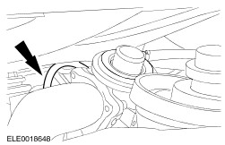
Disconnect the exhaust front pipe from the exhaust manifold. - Discard the gasket and the nuts.
| | | -
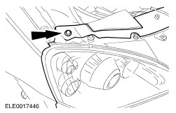
Disconnect the exhaust front pipe from the catalytic converter and detach the exhaust system from the exhaust hanger insulators. - Discard the gasket and the nuts.
| | | -
Disconnect the vacuum hose from the turbocharger boost pressure control. | Vehicles with 130 PS diesel engine | | -
Remove the retaining clip and disconnect the coolant hose from the distribution tube. | All vehicles | | -
CAUTION:Support the halfshaft. The inner joint must not be bent more than 20 degrees. The outer joint must not be bent more than 50 degrees. Detach the left-hand halfshaft from the transaxle output drive flange. | | | -
CAUTION:Support the halfshaft. The inner joint must not be bent more than 20 degrees. The outer joint must not be bent more than 50 degrees. Detach the right-hand halfshaft from the center bearing carrier. | Vehicles with manual transaxle | | -
Detach the generator positive cable and the ground cable from the starter motor bracket. | Vehicles with automatic transaxle | | -
Detach the ground cable from the transaxle. | | | -
Disconnect the automatic transaxle control electrical connector. | | | -
Disconnect the transmission range (TR) sensor electrical connector. | | | -
Detach the wiring harness from the transaxle. | All vehicles | | -
Remove the engine support insulator. - Remove the bolt.
- Remove and discard the bolts.
| | | -
Detach the power steering line from the engine. | | | -
Remove the power steering pump pulley. | | | -
Remove the power steering pump and secure it to one side. | | | -
Detach the refrigerant line support bracket and disconnect the electrical connector from the A/C compressor. | | | -
Detach the A/C compressor from the engine and secure it to one side. | | | -
Position a suitable workshop table under the engine and transaxle assembly. | | | -
WARNING:Support the engine and transaxle assembly on wooden blocks and secure it with suitable securing straps. Carefully lower the vehicle until the engine and transaxle assembly is supported by the workshop table (engine and transaxle assembly shown removed for clarity). | | | -
Remove the engine and transaxle rear mount. - Remove the bolt.
- Remove and discard the bolts and the nut.
| | | -
Remove the engine front mount bracket. | | | -
Raise the vehicle carefully and pull the workshop table and the engine and transmission assembly forward. | Vehicles with automatic transaxle | | -
Using the special tool, disconnect the coolant hose from the transaxle fluid cooler. | | | -
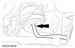
Disconnect the starter motor. - Remove the protective cap.
- Detach the positive cable.
- Disconnect the electrical connector.
| | | -
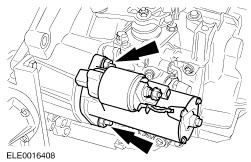
Remove the starter motor. | | | -
Detach the wiring harness from the transaxle. | | | -
Remove the intermediate shaft. | | | -
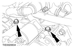
Using the special tool, remove the transaxle left-hand retaining bolts. | | | -
Using the special tool, remove the transaxle right-hand retaining bolts. | | | -
Remove the torque converter plastic cover and the three torque converter nuts. - Rotate the torque converter to gain access to remaining nuts.
| | | -
Using the special tool, remove the transaxle upper retaining bolts. | | | -
Using the special tool, remove the transaxle lower retaining bolts. | | | -
WARNING:Make sure the torque converter remains in the torque converter housing. CAUTION:Do not tilt the transaxle during removal. Remove the transaxle from the engine. | Vehicles with manual transaxle | | -
Disconnect the starter motor. - Remove the protective cap.
- Detach the positive cable.
- Disconnect the electrical connector
| | | -
Remove the starter motor bracket. | | | -
Remove the starter motor. | | | -
Detach the intermediate shaft and the bracket from the right-hand halfshaft. | | | -
Disconnect the vehicle speed sensor (VSS) electrical connector. | | | -
Remove the transaxle left-hand retaining bolts. | | | -
Remove the transaxle right-hand retaining bolts. | | | -
Remove the transaxle upper retaining bolts. | | | -
Remove the transaxle lower retaining bolts. | | | -
Remove the transaxle from the engine. | |