| Assembly Special Tool(s) | | Universal Flange Holding Wrench 205-072 (15-030A) | | | Socket, Cylinder Head Bolt 303-033 (21-002) | | | Locking Tool, Flywheel 303-254 (21–135) | | | Remover/Installer, Hose Clamp 303-397 (24-003) | | | Installer, Crankshaft Seal 303-684 (21-243) | | | Holding Tool, Crankshaft 303-686 (21-244) | | | Holding Tool, Timing Belt Hydraulic Tensioner 310-084 (23-058) | | | Locking Tool, Crankshaft 310-085 (23-059) | | | Wrench, Timing Belt 303-1053 | | | Locking Tool 303-1054 | General Equipment Piston ring compressor 4 mm drill bit 6 mm drill bit Engine hoist Materials Name Specification Sealer SM-M8G1013-AA Sealer AMV 188 100 02 (VW) Sealer AMV 188 100 02 (VW) Sealer AMV 174 004 01 (VW) Silicon sealer D176 404 A2 (VW) Engine Oil WSS-M2C913-A All vehicles | | -
Install the piston cooling oil spray nozzles (four). | | | -
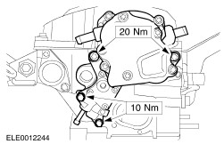
NOTE:Note the protrusion of the engine speed sensor pin from the crankshaft. NOTE:Install new engine speed sensor retaining bolts. Install the engine speed sensor ring. - Install the engine speed sensor ring to the crankshaft.
- Tighten the bolts.
- Check the protrusion of the engine speed sensor pin.
| | | -
CAUTION:Do not damage the crankshaft bearing shells during installation. Install the bearing shells and thrust half-washers free of oil. | | | -
NOTE:Coat the crankshaft bearing shells with clean engine oil. Install the crankshaft, bearing shells, bearing caps and thrust half-washers. - Coat the bearing caps bolts with clean engine oil.
- Tighten the bolts in two stages.
| | | -
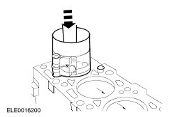
CAUTION:The lug on the side of the connecting rod faces the timing belt end. CAUTION:Do not damage the cylinder bores and the bearing surfaces. NOTE:Pistons No. 1 and No. 2 with the large inlet valve recess facing the flywheel. Pistons No. 3 and No. 4 with the large inlet valve recess facing the timing belt end. One new pistons the cylinder allocation is stamped onto the piston crown (1/2 or 3/4). NOTE:Coat the cylinder bores with engine oil. NOTE:Arrange the piston ring gaps evenly around the circumference and compress them using a proprietary piston ring compressor. Install connecting rod bearing caps and the pistons. | | | -
CAUTION:The upper bearing shell of the connecting rod (facing the piston) is made of a special material and marked with a black line. This line may not be recognizable at used bearing shells. Therefore do not mix-up the bearing shells during installation. NOTE:Coat the crankshaft bearing shells and the crankshaft with clean engine oil. NOTE:Install new bearing cap retaining bolts. Install the connecting rod bearing caps. - Tighten the bolts in two stages.
| | | -
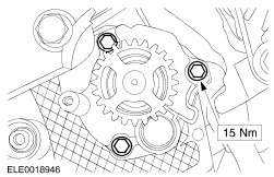
Install the oil pump chain together with the oil pump sprocket and the oil pump chain tensioner. | | | -
CAUTION:The diameter of the bead of sealer must not be larger than 3 mm. Apply a 2.5 mm diameter bead of silicon sealer to the mating face of the crankshaft front seal carrier. | | | -
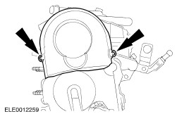
CAUTION:Allow the silicon sealer to dry for approximately 30 minutes. Install the crankshaft front seal carrier. | | | -
NOTE:Do not coat the sealing lip with engine oil or grease. NOTE:Install a new crankshaft seal. Using the special tool and the alignment sleeve, install the crankshaft front seal. - Discard the crankshaft timing pulley center bolt after installation of the crankshaft front seal.
| | | -
NOTE:Install a new crankshaft rear seal. NOTE:Do not coat the sealing lip with engine oil or grease. Install the crankshaft rear seal carrier. | | | -
NOTE:Install a new crankshaft timing retaining bolt. Using the special tool, install the crankshaft timing pulley. - Tighten the bolt in two stages.
| | | -
CAUTION:The diameter of the bead of sealer must not be larger than 3 mm. NOTE:Install the oil pan within five minutes of applying the silicon sealer. | | | -
CAUTION:Allow the silicon sealer to dry for approximately 30 minutes after installation. Install the oil pan (20 bolts). | | | -
CAUTION:Do not bend the adapter plate. NOTE:Install new flywheel retaining bolts. Using the special tool, install the adapter plate and the flywheel. | | | -
Install the clutch disc and pressure plate.
For additional information, refer to: Clutch Disc and Pressure Plate (308-01 Clutch, Removal and Installation).
| | | -
Select the cylinder head gasket.
For additional information, refer to: Specifications (303-01D Engine - 1.9L Diesel, Specifications).
| | | -
Rotate the crankshaft in its normal direction until piston No. 1 is 90 degrees before top dead center (TDC). | | | -
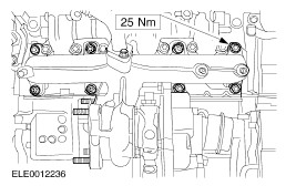
CAUTION:Make sure that the cylinder head bolt washers are installed. NOTE:Install new cylinder head bolts and a new cylinder head gasket. Using the special tool, install the cylinder head. - Tighten the bolts in the sequence shown in four stages.
| | | -
Install the timing belt rear cover. | | | -
Install the camshaft position (CMP) sensor. | | | -
NOTE:Do not tighten the camshaft pulley retaining bolts at this stage. Install the camshaft pulley hub together with the camshaft pulley and tighten the camshaft pulley center bolt. | | | -
NOTE:Install the valve cover within five minutes of applying the silicon sealer. Apply a 5 mm diameter point to the front and rear camshaft bearing caps. | | | -
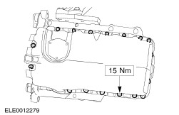
NOTE:Inspect the valve cover gasket for damage. Install a new valve cover gasket if damaged. Install the valve cover and tighten the bolts in the sequence shown. | | | -
NOTE:Install a new coolant pump O-ring seal. Install the coolant pump. | | | -
WARNING:Wrap the flutes of the drill bit with a suitable tape. Failure to follow this instruction may result in personal injury. Rotate the camshaft in its normal direction and insert a 6 mm drill bit through the hole in the cylinder head. | | | -
Rotate the crankshaft in its normal direction until the marks on the crankshaft timing pulley face vertically upwards. | | | -
NOTE:Make sure the marks on the crankshaft timing pulley and on the special tool face one another exactly. The special tool must be installed from the front to the sprocket and engage in the bore of the crankshaft front oil seal carrier mating face. Install the special tool. | | | -
Rotate the camshaft pulley clockwise until it stops at the 6 mm drill bit. | Vehicles with hydraulic timing belt tensioner | | -
NOTE:Do not tighten the nut at this stage. Install the timing belt tensioner pulley. | | | -
NOTE:Install a new timing belt. Install the timing belt beginning with the camshaft pulley followed by the timing belt tensioner, crankshaft timing belt pulley and water pump pulley. | | | -
Install the timing belt tensioner. | | | -
Tension the timing belt. - Using the special tool, rotate the timing belt tensioner cam counterclockwise and remove the special tool.
| | | -
WARNING:Wrap the flutes of the drill bit with a suitable tape. Failure to follow this instruction may result in personal injury. NOTE:Use a new 4 mm drill bit. Adjust the timing belt tensioner. - Using the special tool, rotate the timing belt tensioner cam clockwise until the 4 mm drill bit can be inserted.
- Tighten the timing belt tensioner retaining nut in two stages.
| Vehicles with mechanical timing belt tensioner | | -
Rotate the camshaft pulley counterclockwise until its stop. | | | -
NOTE:Install a new timing belt. Install the timing belt beginning with the camshaft pulley followed by the timing belt tensioner, crankshaft timing belt pulley and water pump pulley. | | | -
CAUTION:The timing belt tensioner tang must be correctly located in the timing belt rear cover. Locate the timing belt tensioner tang in the timing belt rear cover. | | | -
Loosen the timing belt tensioner retaining nut. - Using the special tool, rotate the timing belt tensioner cam counterclockwise and remove the special tool.
| | | -
Adjust the timing belt tensioner. - Using the special tool, rotate the timing belt tensioner cam clockwise until the arrow points at the mark.
- Tighten the timing belt tensioner retaining nut in two stages.
| All Vehicles | | -
Using the special tool, tighten the camshaft pulley retaining bolts. | | | -
Remove the 6 mm drill bit. | | | -
Check the valve timing. - Rotate the crankshaft two revolution in its normal direction and set piston No. 1 at top dead center (TDC).
| | | -
NOTE:Make sure the marks on the crankshaft timing pulley and on the special tool face one another exactly. The special tool must be installed from the front of the sprocket and engage in the bore of the crankshaft front seal carrier mating face. Install the special tool. | Vehicles with hydraulic timing belt tensioner | | -
WARNING:Wrap the flutes of the drill bit with a suitable tape. Failure to follow this instruction may result in personal injury. Check the timing belt tensioner setting by inserting the 4 mm drill bit. | Vehicles with mechanical timing belt tensioner | | -
Check that the arrow points to the mark. | All Vehicles | | -
WARNING:Wrap the flutes of the drill bit with a suitable tape. Failure to follow this instruction may result in personal injury. Insert a 6 mm drill bit through the hole in the camshaft pulley. If the drill bit can not be inserted, loosen the camshaft pulley retaining bolts, insert the drill bit and tighten the camshaft pulley retaining bolts. | | | -
Install the timing belt lower cover. | | | -
Install the timing belt center cover. | | | -
Install the crankshaft pulley. - Tighten the bolts in two stages.
| | | -
Install the timing belt upper cover. | | | -
Install the engine support plate. | | | -
NOTE:Install new exhaust manifold gaskets. Install the exhaust manifold and turbocharger assembly. | | | -
Connect the turbocharger oil return tube to the engine. | | | -
Install the exhaust heat shield to the exhaust manifold. | | | -
NOTE:Install a new intake manifold gasket. NOTE:The coating of the intake manifold gasket faces the intake manifold. Install the intake manifold. | | | -
NOTE:Install new exhaust gas recirculation (EGR) tube gaskets. Install the EGR tube. | | | -
Attach the charge air cooler intake pipe bracket to the oil pan. | | | -
Install the charge air cooler intake pipe. | | | -
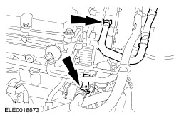
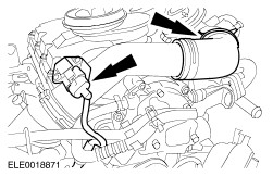
NOTE:Install a new O-ring seal if necessary. Install the turbocharger intake pipe and connect the positive crankcase ventilation (PCV) hose to the valve cover. | | | -
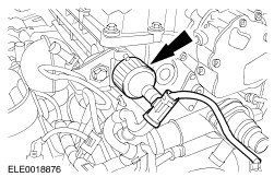
NOTE:Install a new O-ring seal. Install the vacuum and fuel pump. | | | -
NOTE:Install a new O-ring seal. Install the coolant outlet housing. | | | -
NOTE:Install a new O-ring seal. Install the crankshaft position (CKP) sensor. | | | -
NOTE:Install a new oil filter housing gasket. Install the oil filter housing. | | | -
NOTE:Install a new O-ring seal. Install the coolant distribution tube. | | | -
Connect the turbocharger oil supply line to the turbocharger. | | | -
Connect the turbocharger oil supply line to the oil filter housing. - Attach the oil supply line to the cylinder block.
| | | -
Install the oil level indicator and tube. | | | -
NOTE:Install a new O-ring seal. Install the thermostat and the thermostat housing. | | | -
Install the vacuum reservoir. | | | -
Install the power steering, air conditioning (A/C) compressor and generator bracket. - Tighten the bolts in the sequence shown.
| | | -
Install the accessory drive belt tensioner. | | | -
Install the engine wiring harness to the engine. | | | -
Connect the battery positive cable to the generator. | | | -
Connect the generator electrical connector. | | | -
Connect the oil pressure switch electrical connector and attach the ground cable. | | | -
Connect the CKP sensor electrical connector. - Attach the CKP sensor electrical connector to the retaining bracket.
| | | -
Connect the camshaft position (CMP) sensor electrical connector. - Attach the CMP sensor electrical connector to the retaining bracket.
| | | -
Connect the power supply rail to the glow plugs. | | | -
Connect the electrical connectors to the unit injectors. | | | -
Connect the engine coolant temperature (ECT) sensor electrical connector . | | | -
Connect the oil level sensor and oil temperature sensor electrical connector. | | | -
Connect the fuel lines to the fuel pump. | | | -
Connect the fuel temperature sensor electrical connector. | | | -
Install the intake air pipe and connect the manifold absolute pressure (MAP) sensor and the intake air temperature (IAT) sensor electrical connector. | | | -
Using the special tool, connect the coolant hoses. | | | -
Remove the special tools from the engine. | |