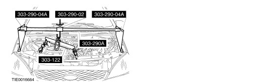
| Installation Special Tool(s) | | Support Bar, Engine 303-290A (21-140A) | | | Adapter for 303-290A 303-290-02 (21-140-02) | | | Adapter for 303-290A 303-290-04A (21-140-04A) | | | Lifting Bracket, Engine 303-122 (21-068A) | | | Splined Bit Set (M12/M14) 303-702 (21-253) | General Equipment Retaining straps Transmission jack Steel straight edge Materials Name Specification Automatic transmission fluid N052990VX00 Installation | | -
CAUTION:The torque converter must remain at the correct installation depth throughout the whole installation procedure. NOTE:The torque converter studs must be aligned with the engine drive plate holes before any transaxle retaining bolts are installed. Install the torque converter. | | | -
CAUTION:The torque converter hub must engage fully in the oil pump drive gear. Check the installation depth of the torque converter. - Using a suitable straight edge, check the installation depth between the transaxle flange and the drive plate studs.
| | | -
NOTE:Secure the transaxle to the transmission jack with the retaining straps before raising the transaxle. | | | -
NOTE:Do not fully tighten the transaxle retaining bolts at this stage. Install the transaxle retaining bolts. - Install the M12 x 40 mm bolt.
- Install the M12 x 50 mm bolt.
- Install the M12 x 65 mm bolt.
- Install the M12 x 60 mm bolt.
- Install the M10 x 55 mm bolts.
- Install the M12 x 70 mm bolt.
| | | -
Tighten the transaxle right-hand retaining bolts. | | | -
Using the special tool, tighten the transaxle left-hand retaining bolts (two bolts). - Install the transaxle ground connection.
| | | -
Using the special tool, tighten the transaxle right-hand retaining bolt. | | | -
Using the special tool, tighten the transaxle lower retaining bolts. | | | -
NOTE:Install new torque converter retaining nuts. Install the torque converter retaining nuts. - Rotate the torque converter to gain access to the remaining nuts.
- Install the plastic cover.
| | | -
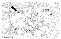
NOTE:Install new transaxle rear mount retaining bolts. Install the engine and transaxle rear mount retaining bracket. - Tighten the bolts in two stages.
| | | -
Using the special tools, raise the engine and transaxle assembly. | | | -
NOTE:Install new engine and transaxle rear mount retaining nuts and bolts at position 2 and 3. Install the engine and transaxle rear mount retaining nut and bolts. - Tighten the bolt.
- Tighten the bolts and nut in two stages
- Tighten the nut in two stages
| | | -
Remove the special tools. | | | -
CAUTION:Support the halfshaft. The inner joint must not be bent more than 20 degrees. The outer joint must not be bent more than 50 degrees. Attach the left-hand halfshaft to the output shaft drive flange. | | | -
CAUTION:Support the halfshaft. The inner joint must not be bent more than 20 degrees. The outer joint must not be bent more than 50 degrees. NOTE:Install new center bearing locknuts. Attach the right-hand halfshaft and the intermediate shaft to the output shaft drive flange. - Attach the intermediate shaft to the output shaft drive flange.
- Attach the center bearing to the bearing carrier (two bolts, one bolt shown).
| | | -
Attach the lower arms to the wheel knuckles. | | | -
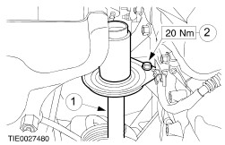
Install the engine support insulator. - Tighten the bolt.
- Tighten the bolts in two stages.
| | | -
Connect the transaxle control electrical connector. - Rotate the locking lever clockwise.
| | | -
Attach the cable bracket to the transaxle fluid pan (three nuts). | | | -
Attach the ground cable to the transaxle. | | | -
Install the secondary air injection (AIR) pump. - Connect the hose.
- Connect the electrical connector.
- Install the bolts.
| | | -
Install the AIR pump intake pipe and ball valve. | | | -
NOTE:Install a new exhaust flange gasket. Attach the exhaust pipe to the exhaust downpipe (three bolts). | | | -
Attach the radiator grille opening panel reinforcement to the fender on both sides. | | | -
NOTE:Install new transaxle fluid cooler O-ring seals NOTE:Check the install position. Attach the transaxle fluid cooler to the transaxle case. | | | -
Tighten the transaxle upper retaining bolt. | | | -
Install the starter motor (two bolts). | | | -
Connect the transmission range (TR) sensor electrical connector. | | | -
Attach the selector lever cable to the transaxle. - Attach the selector lever cable to the manual control lever.
- Attach the selector lever cable bracket to the transaxle.
| | | -
Attach the selector lever cable to the selector lever cable bracket. | | | -
Connect the starter motor cables. - Connect the starter motor electrical connector.
- Attach the battery cable to the starter motor solenoid.
- Install the protective cap.
| | | -
Install the battery tray. | | | -
Attach the engine wiring harness rail to the battery tray. | | | -
Install the battery side cover. | | | -
Connect the engine wiring harness electrical connectors. - Attach the wiring harness to the battery tray.
| | | -
Connect the engine coolant level indicator electrical connector. | | | -
Install the bulkhead cover. | | | -
Check that the selector lever position indicator corresponds with the transaxle operation. | | | -
Install the engine and battery upper cover. | | |