| Removal Special Tool(s) | | Support Bar, Engine 303-290A (21-140A) | | | Adapter for 303-290A 303-290-02 (21-140-02) | | | Adapter for 303-290A 303-290-04A (21-140-04A) | | | Lifting Bracket, Engine 303-122 (21-068A) | | | Splined Bit Set (M12/M14) 303-702 (21-253) | General Equipment Retaining straps Transmission jack | | -
NOTE:Carry out this step, if an auxiliary battery is installed. | | | -
NOTE:Shift the selector lever into "P" (park) position. | | | -
Remove the engine upper cover. | | | -
Remove the bulkhead cover. | | | -
Disconnect the engine coolant level indicator electrical connector. | | | -
Detach the wiring harness electrical connector from the battery tray. | | | -
Remove the battery side cover. | | | -
Detach the engine wiring harness rail from the battery tray. | | | -
Disconnect the starter motor cables. - Remove the protective cap.
- Detach the battery cable from the starter motor solenoid.
- Disconnect the starter motor electrical connector.
| | | -
Detach the selector lever cable from the transaxle. - Detach the selector lever cable bracket from the transaxle.
- Detach the selector lever cable from the manual control lever.
| | | -
Detach the selector lever cable from the retaining clip. | | | -
Disconnect the transmission range (TR) sensor electrical connector. | | | -
Remove the starter motor (two bolts, one bolt shown). | | | -
Remove the transaxle upper retaining bolt. | | | -
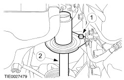
Detach the transaxle fluid cooler from the transaxle case. - Discard the O-ring seals.
| | | -
Detach the radiator grille opening panel reinforcement from the fender on both sides. | | | -
Install the special tools. | | | -
Remove the engine and transaxle rear mount. - Remove the bolt.
- Remove and discard the bolts and the nut.
| | | -
Remove the engine mount retaining bracket. | | | -
Remove the engine undershield. | | | -
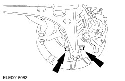
Detach the exhaust pipe from the exhaust downpipe (three bolts). | | | -
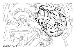
Remove the secondary air injection (AIR) pump. - Remove the bolts.
- Disconnect the electrical connector.
- Disconnect the hose.
| | | -
Disconnect the transaxle control unit electrical connector. - Rotate the locking lever counterclockwise.
| | | -
Detach the ground cable from the transaxle. | | | -
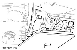
Detach the cable bracket from the transaxle fluid pan (three nuts, one nut shown). | | | -
CAUTION:Protect the ball joint seal using a soft cloth to prevent damage. Detach the lower arms from the wheel knuckles on both sides. | | | -
CAUTION:Support the halfshaft. The inner joint must not be bent more than 20 degrees. The outer joint must not be bent more than 50 degrees. Detach the right-hand halfshaft and the intermediate shaft from the output shaft drive flange. - Detach the center bearing from the bearing carrier.
- Detach the intermediate shaft from the output shaft drive flange.
- Secure the left-hand halfshaft to one side, using cable ties.
- Discard the center bearing locknuts.
| | | -
CAUTION:Support the halfshaft. The inner joint must not be bent more than 20 degrees. The outer joint must not be bent more than 50 degrees. Detach the left-hand halfshaft from the output shaft drive flange. - Secure the left-hand halfshaft to one side, using cable ties.
| | | -
Remove the engine support insulator. | | | -
Using the special tools, lower the engine and transaxle assembly. | | | -
Remove the torque converter retaining nuts. - Remove the plastic cover.
- Rotate the torque converter to gain access to the remaining nuts.
| | | -
Using the special tool, remove the transaxle left-hand retaining bolts. | | | -
Remove the transaxle right-hand retaining bolts. | | | -
WARNING:Make sure the torque converter remains in the torque converter housing. NOTE:Use a suitable wooden block to protect the transaxle. | | | -
NOTE:Secure the transaxle with the retaining straps. Lower the transaxle. | | |