| Removal and Installation Removal | | -
CAUTION:If brake fluid is spilt on the paintwork, the affected area must be immediately washed down with cold water. | | | -
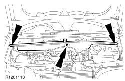
Remove the bulkhead cover. | | | -
Disconnect the engine wiring harness and the engine coolant level sensor electrical connectors. | | | -
Remove the battery side cover. - Detach the cooling system degas hose from the battery side cover.
- Detach the engine wiring harness electrical connector from the retaining bracket.
| | | -
WARNING:Allow the engine to cool before removing the coolant expansion tank cap. Failure to follow this instruction may result in personal injury. Remove the coolant expansion tank retaining bolts. - Drain the coolant expansion tank.
- Allow the coolant to drain into a suitable container.
| | | -
Disconnect the coolant hoses from the coolant expansion tank. - Remove the coolant expansion tank.
| | | -
Disconnect the hydraulic control unit (HCU) electrical connector. | | | -
CAUTION:Cap the brake tubes to prevent fluid loss or dirt ingress. NOTE:Mark the position of the brake tubes to aid installation. Disconnect the brake tubes from the HCU. | | | -
Remove the HCU. - Discard the nuts and the bolt.
| | | -
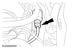
CAUTION:Clamp the brake fluid supply hose to prevent fluid loss. Disconnect the brake fluid supply hose from the clutch master cylinder. - Remove the clip.
- Use a suitable brake hose clamp, clamp the supply hose.
| | | -
CAUTION:The clutch master cylinder will be removed from the passenger compartment. Cap the clutch master cylinder to prevent fluid loss or dirt ingress. Disconnect the clutch master cylinder pressure pipe from the clutch master cylinder. | | | -
Remove the instrument finish panel. | | | -
Remove the instrument panel lower trim panel lower retaining screws. - Remove the central junction box (CJB) cover plate.
| | | -
Remove the driver side instrument panel side trim. | | | -
Remove the footwell insulation panel. | | | -
Remove the instrument panel lower trim panel upper retaining screws. - Remove the lower trim panel.
| | | -
Disconnect the electrical connectors from the instrument panel lower trim panel. - Disconnect the multifunction light switch from the lower trim panel.
- Disconnect the headlamp alignment control and instrument illumination control multifunction switch from the lower trim panel.
- Detach the data link connector (DLC) from the lower trim panel.
| | | -
Detach the CJB from the cross-vehicle beam. | | | -
Detach the CJB from the bracket and position it to one side. | | | -
Remove the clutch pedal cover. | | | -
Detach the clutch pedal position (CPP) switch from the clutch pedal bracket. - Turn the switch counterclockwise.
| | | -
Detach the clutch pedal return spring from the bracket. | | | -
Remove the clutch pedal and the clutch master cylinder assembly. - Remove the bolts.
- Remove the clip.
| | | -
Remove the clutch master cylinder. | Installation | | -
Install the clutch master cylinder. | | | -
NOTE:Turn the clutch pedal return spring into the installation position. Install the clutch pedal. - Attach the clutch master cylinder actuating rod to the clutch pedal.
| | | -
Attach the clutch pedal return spring to the bracket. | | | -
Attach the clutch pedal position (CPP) switch to the clutch pedal bracket. - Turn the switch clockwise.
| | | -
Install the clutch pedal cover. | | | -
Attach the CJB to the bracket. | | | -
Attach the CJB to the cross-vehicle beam. | | | -
Connect the electrical connectors to the instrument panel lower trim panel. - Connect the multifunction light switch to the lower trim panel.
- Connect the headlamp alignment and instrument control multifunction switch to the lower trim panel.
- Attach the data link connector (DLC) to the lower trim panel.
| | | -
Install the instrument panel lower trim panel. | | | -
Install the instrument panel lower trim panel lower retaining screws. - Install the CJB cover plate.
| | | -
Install the instrument finish panel. | | | -
Install the driver side instrument panel side trim. | | | -
Install the footwell insulation pad. | | | -
Connect the clutch master cylinder pressure pipe to the clutch master cylinder. | | | -
Connect the brake fluid supply hose to the clutch master cylinder. | | | -
NOTE:Install new hydraulic control unit (HCU) retaining nuts and bolt. Install the HCU. | | | -
NOTE:Observe the markings. Connect the brake tubes to the HCU. | | | -
Connect the HCU electrical connector. | | | -
NOTE:Position the coolant expansion tank. Connect the coolant hoses to the expansion tank. | | | -
Install the battery side cover. - Attach the coolant system degas hose to the battery side cover.
- Connect the engine wiring harness electrical connector to the retaining bracket.
| | | -
Install the coolant expansion tank retaining bolts. | | | -
- Install the expansion tank cap.
| | | -
Connect the engine wiring harness and the engine coolant level sensor electrical connectors. | | | -
Install the bulkhead cover. | | |