| PINPOINT TEST A : THE FOG LAMPS ARE INOPERATIVE |
| TEST CONDITIONS | DETAILS/RESULTS/ACTIONS |
| A1: DETERMINE THE FAULT CONDITION |
| | 1 Determine the fault condition. |
| | Are the front fog lamps inoperative? Yes Rear fog lamps are inoperative: GO to A2. No Rear fog lamps are inoperative: - vehicles with detachable towbar: GO to A7. |
| A2: CHECK FUSE F26 (CJB) |
| | 1 Ignition switch in position 0. |
| | 2 CHECK Fuse F26 (CJB). |
| | 3 Check fuse F26 (15 A). |
| | Is the fuse OK? Yes No INSTALL a new fuse F26 (15 A) and TEST the system for normal operation. If the fuse blows again, LOCATE and REPAIR the short circuit by using the wiring diagrams. TEST the system for normal operation. |
| A3: CHECK THE VOLTAGE AT FUSE F26 (CJB) |
| | 1 Connect Fuse F26 (CJB). |
| | 2 Ignition switch in position II. |
| | 3 Measure the voltage between fuse F26 (15 A) and ground. |
| | Is battery voltage indicated? Yes No LOCATE and REPAIR the open, in circuit between splice S8 and fuse F26, by using the wiring diagrams. If necessary INSTALL a new CJB. TEST the system for normal operation. |
| A4: CHECK THE VOLTAGE AT THE LIGHT SWITCH |
| | 1 Ignition switch in position 0. |
| | 2 Disconnect Light switch C168. |
| | 3 Ignition switch in position II. |
| | 4 Measure the voltage between light switch, connector C168, pin 2, circuit (GY/YE), harness side and ground. |
| | Is battery voltage indicated? Yes CHECK the light switch according to the Component Test attached to procedure Headlamps, if necessary INSTALL a new one. TEST the system for normal operation. No LOCATE and REPAIR the open, in circuit between fuse F26 and light switch, by using the wiring diagrams. If necessary INSTALL a new CJB. TEST the system for normal operation. |
| A5: CHECK THE VOLTAGE AT THE FRONT FOG LAMP |
| | 1 Ignition switch in position 0. |
| | 2 Disconnect Front fog lamp right-hand side C379. |
| | 3 Ignition switch in position II. |
| | 4 Turn on the FRONT FOG LAMPS. |
| | 5 Measure the voltage between front fog lamp right-hand side, connector C379, pin 1, circuit (GY/YE), harness side and ground. |
| | Is battery voltage indicated? Yes REPAIR the open circuit (BN), between splice S87 and ground G5, by using the wiring diagrams. TEST the system for normal operation. No |
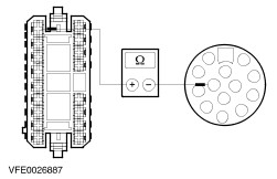
| A6: CHECK CIRCUIT BETWEEN LIGHT SWITCH AND FOG LAMP FOR OPEN |
| | 1 Ignition switch in position 0. |
| | 2 Disconnect Light switch C168. |
| | 3 Measure the resistance between front fog lamp right-hand side, connector C379, pin 1, circuit (GY/YE), harness side and light switch, connector C168, pin 8, circuit (GY/BN), harness side. |
| | Is the resistance less than 2 ohms? Yes CHECK the light switch according to the Component Test attached to procedure Headlamps, if necessary INSTALL a new one. TEST the system for normal operation. No REPAIR the open circuit (GY/BN), between light switch and splice S86, by using the wiring diagrams. TEST the system for normal operation. |
| A7: CHECK THE VOLTAGE AT THE TRAILER SOCKET |
| | 1 Ignition switch in position II. |
| | 2 Turn on the REAR FOG LAMPS. |
| | 3 Measure the voltage between trailer socket, socket C350, pin 2, circuit (GY) and ground. |
| | Is battery voltage indicated? Yes No |
| A8: CHECK THE CIRCUIT BETWEEN LIGHT SWITCH AND TRAILER SOCKET FOR OPEN |
| | 1 Ignition switch in position 0. |
| | 2 Disconnect Light switch C168. |
| | 3 Measure the resistance between light switch, connector C168, pin 9, circuit (GY), harness side and trailer socket, socket C350, pin 2, circuit (GY). |
| | Is the resistance less than 2 ohms? Yes CHECK the light switch according to the Component Test attached to procedure Headlamps, if necessary INSTALL a new one. TEST the system for normal operation. No REPAIR the open circuit (GY), between light switch and trailer socket, by using the wiring diagrams. TEST the system for normal operation. |
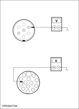
| A9: CHECK THE VOLTAGE AT THE TRAILER SOCKET |
| | 1 Ignition switch in position II. |
| | 2 Turn on the REAR FOG LAMPS. |
| | 3 Measure the voltage between - 7-pin trailer socket C557, pin 2, circuit (RD/YE) and ground.
- 13-pin trailer socket C605, pin 2, circuit (RD/YE) and ground.
|
| | Is battery voltage indicated? Yes No |
| A10: CHECK THE VOLTAGE AT THE REAR FOG LAMP CUT-OFF RELAY |
| | 1 Ignition switch in position 0. |
| | 2 Disconnect Rear fog lamp cut-off relay C552. |
| | 3 Ignition switch in position II. |
| | 4 Turn on the REAR FOG LAMPS. |
| | 5 Measure the voltage between rear fog lamp cut-off relay, socket C552, circuit (RD/WH), harness side and ground. |
| | Is battery voltage indicated? Yes INSTALL a new rear fog lamp cut-off relay. TEST the system for normal operation. No |
| A11: CHECK THE CIRCUIT BETWEEN LIGHT SWITCH AND REAR FOG LAMP CUT-OFF RELAY FOR OPEN |
| | 1 Ignition switch in position 0. |
| | 2 Disconnect Light switch C168. |
| | 3 Measure the resistance between light switch, connector C168, pin 9, circuit (GY), harness side and rear fog lamp cut-off relay, connector C552, circuit (RD/WH), harness side. |
| | Is the resistance less than 2 ohms? Yes CHECK the light switch according to the Component Test attached to procedure Headlamps, if necessary INSTALL a new one. TEST the system for normal operation. No REPAIR the open circuit (GY) resp. (RD/WH), between light switch and rear fog lamp cut-off relay, by using the wiring diagrams. TEST the system for normal operation. |
| A12: CHECK THE VOLTAGE AT THE REAR FOG LAMP |
| | 1 Ignition switch in position 0. |
| | 2 Disconnect Tailgate lamp assembly left-hand side C285. |
| | 3 Ignition switch in position II. |
| | 4 Turn on the REAR FOG LAMPS. |
| | 5 Measure the voltage between tailgate lamp assembly left-hand side, connector C285, pin 3, circuit (GY/WH), harness side and ground. |
| | Is battery voltage indicated? Yes REPAIR the circuit (BN), between splice S66 and ground G8, by using the wiring diagrams. TEST the system for normal operation. No |
| A13: CHECK THE CIRCUIT BETWEEN LIGHT SWITCH AND REAR FOG LAMPS FOR OPEN |
| | 1 Ignition switch in position 0. |
| | 2 Disconnect Light switch C168. |
| | 3 Measure the resistance between light switch, connector C168, pin 9, circuit (GY), harness side and tailgate assembly left-hand side, connector C285, pin 3, circuit (GY/WH), harness side. |
| | Is the resistance less than 2 ohms? Yes CHECK the light switch according to the Component Test attached to procedure Headlamps, if necessary INSTALL a new one. TEST the system for normal operation. No REPAIR the open circuit (GY) resp. (GY/WH), between light switch and splice S89, by using the wiring diagrams. TEST the system for normal operation. |
| A14: CHECK THE REAR FOG LAMP CUT-OFF RELAY |
| | 1 Ignition switch in position 0. |
| | 2 Connect Tailgate lamp assembly left-hand side C285. |
| | 3 Connect a fused jumper wire (15 A) at the rear fog lamp cut-off relay, socket C552, between circuit (RD/WH) and circuit (VT/YE), harness side. |
| | 4 Ignition switch in position II. |
| | 5 Turn on the REAR FOG LAMPS. |
| | 6 CHECK the rear fog lamps. |
| | Do the rear fog lamps illuminate? Yes INSTALL a new rear fog lamp cut-off relay. TEST the system for normal operation. No REPAIR the open circuit (VT/YE) resp. (GY/WH), between rear fog lamp cut-off relay and splice S89, by using the wiring diagrams. TEST the system for normal operation. |
| A15: CHECK THE CIRCUIT BETWEEN TRAILER SOCKET AND TRAILER TOW MICRO SWITCH FOR OPEN |
| | 1 Ignition switch in position II. |
| | 2 Turn on the REAR FOG LAMPS. |
| | 3 Measure the voltage between trailer tow micro switch, connector C365, pin 3, circuit (GY), harness side and ground. |
| | Is battery voltage indicated? Yes No REPAIR the open circuit (GY), between trailer socket and trailer tow micro switch, by using the wiring diagrams. TEST the system for normal operation. |
| A16: CHECK THE TRAILER TOW MICRO SWITCH |
| | 1 Ignition switch in position 0. |
| | 2 Connect Tailgate lamp assembly left-hand side C285. |
| | 3 Connect a fused jumper wire (15 A) at the trailer tow micro switch, connector C365, between pin 3, circuit (GY) and pin 1, circuit (GY/WH), harness side. |
| | 4 Ignition switch in position II. |
| | 5 Turn on the REAR FOG LAMPS. |
| | 6 CHECK the rear fog lamps. |
| | Do the rear fog lamps illuminate? Yes INSTALL a new trailer tow micro switch. TEST the system for normal operation. No REPAIR the open circuit (GY/WH), between trailer tow micro switch and splice S89, by using the wiring diagrams. TEST the system for normal operation. |