| Removal and Installation Special Tool(s) | | Installer, Halfshaft 204-161 (14-041) | | | Clamping Tool, Boot Retaining Clamp 204-169 (14-044) | General Equipment 32 mm socket Two-legged puller Materials Name Specification High-durability grease WSD-M2C230-A Boot clamps Removal | | -
NOTE:Use an Allen key to prevent the piston rod turning. Loosen the left-hand and the right-hand strut and spring assembly upper retaining nut five turns (right-hand side shown). | | | -
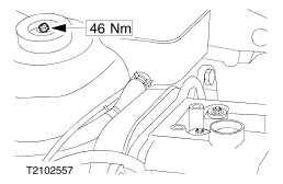
Loosen the left-hand wheel nuts and loosen the stub axle nut. | | | -
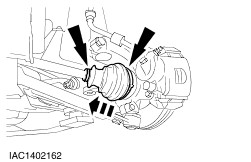
Detach the right-hand and the left-hand lower arms (left-hand side shown). | | | -
Separate and discard the boot clamps. - Slide the boot back onto the halfshaft.
- Remove the grease from inside the joint.
| | | -
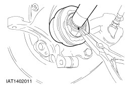
CAUTION:The inner joint must not be bent at more than 18 degrees, the outer joint must not be bent at more than 45 degrees. Remove the front drive halfshaft from the constant velocity joint. - Lever open the retaining ring and hold it open.
- Carefully push the spindle carrier outwards and withdraw the front drive halfshaft.
- Lift up the front drive halfshaft and tie it up.
- Remove the retaining ring from the constant velocity joint.
| | | -
Remove the front drive halfshaft nut and take off the washer. - Using a two-legged puller to press the left-hand halfshaft out of the wheel hub and tie it up.
| Installation | | -
NOTE:Use all new circlips, self-locking nuts and clamps. Draw the front drive halfshaft stub into the wheel hub. - Insert the washer and screw on the front drive halfshaft stub nut.
| | | -
CAUTION:The inner constant velocity joint must not be bent at more than 18 degrees, the outer joint must not be bent at more than 45 degrees. NOTE:Make sure the retaining ring is securely in place. Install the drive halfshaft in the constant velocity joint. - Guide the front drive halfshaft into the constant velocity joint until the retaining ring clips in place.
| | | -
Fabricate an adapter for special tool 14-044. - Material: aluminium or steel plate, 5 mm thick.
| | | -
- Amount: 40 grams on each side.
| | | -
NOTE:Tighten 0,8 mm thick boot clamps to 12 Nm and 1,1 mm thick boot clamps to 20 Nm. Position the boot and using the special tool and adapter secure the boot clamps. | | | -
Install the lower suspension arm and the front wheel. | | | -
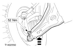
Tighten the wheel nuts and the front drive halfshaft stub nut. - Using a 32 mm socket wrench, tighten the front drive halfshaft stub nut and secure it, using a lock pin.
- Wheel nuts.
| | | -
NOTE:Use an Allen key to prevent the piston rod turning. Tighten the left-hand and the right-hand side strut and spring assembly upper retaining nut. | | |