ford Workshop Repair Guides

Ford Workshop Service and Repair Manuals

Diagnosis and Testing > < 308-03 Manual Transmission-Transaxle|Specifications
Manual Transmission/Transaxle - Manual Transaxle Ikon 1999 (01/2000-)
Description and Operation

Overview

 
Item
Part Number
Description
1
-
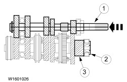
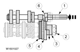
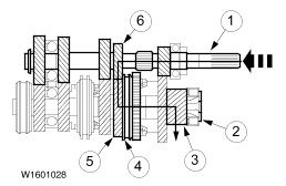
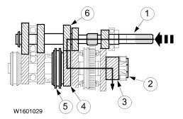
Slave Cylinder - Clutch
2
-
Sealed bearings
3
-
Transmission vent

The aluminium transmission housing features reinforcement ribs for additional strength. Liquid sealer is used between the two halves of the transmission (WSS - M2G348-A5) and the end cover (WSE - M4G323 - A4). On transmissions using liquid sealer the end cover is painted black.

In addition to this, components in the transmission have been modified although their design has not been changed.

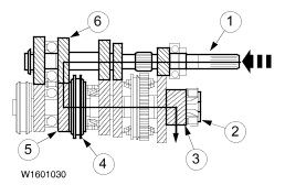
The iB5 manual transmission is a "2 shaft transmission". The clutch is operated hydraulically.

On a "2 shaft transmission" all gearwheels are constantly in mesh. Each gear ratio is achieved through one pair of gearwheels.

The direction of rotation of the output shaft is reversed for reverse gear by using an idler gearwheel.

All gearwheels are helically splined, synchronized (except reverse gear) and run on friction bearings.

This reduces noise to a minimum and provides easy gear changing, together with low weight and compactness.

The spring loaded return slide in the external gearshift mechanism is eliminated by fitting a selector lever relay with return spring inside the transmission.

Components of the iB5 Manual Transmission

Overview

 
Item
Part Number
Description
1
-
Pre-load valve (1 bar) (vehicles built up to build month 08/1999)
2
-
Oil seal (accessible from the outside)
3
-
Clutch release bearing (separately renewable)
4
-
Front drive halfshaft intermediate shaft
5
-
Crown wheel
6
-
Tripode housing
7
-
First/second gear synchronizer clutch
8
-
Third/fourth gear synchronizer clutch
9
-
Fifth gear synchronizer clutch
10
-
Transmission vent

When the transmission is in neutral none of the gearwheels are connected to the output shaft by the synchronizer clutches. No power is transferred to the differential.

Internal Gearshift Mechanism

 
Item
Part Number
Description
1
-
Main shift rod
2
-
Boot (vent pointing downwards)
3
-
Radial oil seal
4
-
Relay lever (select)
5
-
Shift locking plate
6
-
Detent mechanism
7
-
Auxiliary shift rod
8
-
Relay lever (shift)
9
-
Selector block
10
-
Selector gate

Input shaft

 
Item
Part Number
Description
1
-
Ball bearing
2
-
Input shaft
3
-
Reverse gear idler
4
-
Gearwheel - 1st gear
5
-
Gearwheel - reverse gear
6
-
Gearwheel - 2nd gear
7
-
Gearwheel - 3rd gear
8
-
Gearwheel - 4th gear
9
-
Snap-ring
10
-
Gearwheel - 5th gear
11
-
Snap-ring.

Output shaft

 
Item
Part Number
Description
1
-
Parallel roller bearing
2
-
Output shaft
3
-
1st gearwheel
4
-
Inner synchronizer ring
5
-
Synchronizer cone
6
-
Outer synchronizer ring
7
-
1st/2nd gear synchronizer clutch with reverse gearwheel
8
-
Snap-ring
9
-
Outer synchronizer ring
10
-
Synchronizer cone
11
-
Inner synchronizer ring
12
-
2nd gearwheel
13
-
Half rings
14
-
Snap-ring
15
-
3rd gearwheel with simple synchronization
16
-
3rd gearwheel with double synchronization
17
-
Synchronizer clutch - 3rd/4th gear
18
-
Synchronizer ring (4th gear)
19
-
Gearwheel - 4th gear
20
-
Ball bearing (closed on both sides)
21
-
Snap-ring.
22
-
Gearwheel - 5th gear
23
-
Synchronizer ring (5th gear)
24
-
5th gear synchronizer clutch
25
-
Retaining plate

Double synchronization

 
Item
Part Number
Description
1
-
Gearwheel
2
-
Inner synchronizer ring
3
-
Synchronizer cone
4
-
Outer synchronizer ring
5
-
Synchronizer hub

Double synchronization

The first and second gears are double synchronised. Because a second synchronizer ring is used, the effective surface compared with the simple synchronizer is approximately doubled. Ease of gear changing is considerably improved through double synchronization.

The double synchronization components are: inner synchronizer ring, synchronizer cone, outer synchronizer ring and synchronizer hub.

The conical surface on the gearwheel is no longer present. Synchronisation is achieved through the two synchronizer rings and the synchronizer cone which fits on the gearwheel.

Differential

The basic components of the differential are:

  • Crown wheel
  • Differential housing with two taper roller bearings
  • Differential pinions
  • Drive halfshaft pinions

The transmission and differential are located inside an aluminium two part housing which is connected to the engine by a flange.

The input shafts are splined.

Driving torque is transferred to the differential cage by the crownwheel which is bolted to it.

Inside the differential housing are the differential pinions which are located on a spindle, and the drive halfshaft pinions which are connected to the front drive halfshafts by splines.

When there is a speed difference between the two front wheels (for instance when driving through a curve), the front drive halfshaft pinions are able to turn on the differential pinions.

Power Flow

Neutral

 
Item
Part Number
Description
1
-
Input shaft
2
-
Output shaft
3
-
Output pinion

First gear

 
Item
Part Number
Description
1
-
Input shaft
2
-
Output shaft
3
-
Output pinion
4
-
1st gearwheel
5
-
1st/2nd gear synchronizer clutch
6
-
1st gear teeth

Second gear

 
Item
Part Number
Description
1
-
Input shaft
2
-
Output shaft
3
-
Output pinion
4
-
1st/2nd gear synchronizer clutch
5
-
2nd gearwheel
6
-
2nd gear teeth

Third gear

 
Item
Part Number
Description
1
-
Input shaft
2
-
Output shaft
3
-
Output pinion
4
-
3rd gear teeth
5
-
3rd/4th gear synchronizer clutch
6
-
3rd gearwheel

Fourth gear

 
Item
Part Number
Description
1
-
Input shaft
2
-
Output shaft
3
-
Output pinion
4
-
3rd/4th gear synchronizer clutch
5
-
4th gear teeth
6
-
4th gearwheel

Fifth gear

 
Item
Part Number
Description
1
-
Input shaft
2
-
Output shaft
3
-
Output pinion
4
-
5th gear teeth
5
-
5th gear synchronizer clutch
6
-
5th gearwheel

Reverse gear

 
Item
Part Number
Description
1
-
Input shaft
2
-
Output shaft
3
-
Output pinion
4
-
Reverse gearwheel
5
-
Teeth - reverse gear
6
-
Reverse gear idler

The reverse gear idler is driven by the input shaft and its purpose is to reverse the direction of rotation of the output shaft when reverse gear is engaged.

The reverse gear idler is carried on a needle roller bearing on the idler shaft, and also on a mounting.

The detent mechanism and the gear selector finger are mounted on a sleeve in the selector mechanism housing, and they use a spring-loaded ball keep the chosen gear engaged until another gear is selected.

The selector lock mechanism has three selector positions.

Diagnosis and Testing > < 308-03 Manual Transmission-Transaxle|Specifications