| Diagnosis and Testing Refer to Wiring Diagrams Section 413-01, for schematic and connector information. Worldwide Diagnostic System (WDS) (418-F224) Principles of Operation The instrument cluster is a mix of intelligent and hardwired electrical signals and has a built-in self-test feature. The instrument cluster is connected to the powertrain control module (PCM) by a control area network (CAN) bus. This link allows the instrument cluster and the PCM to communicate with each other. The instrument cluster consists of gauges, indicators and warning indicators. When the ignition switch is turned to position II from either position 0 or position I the instrument cluster carries out a display test to verify that the warning indicator or indicator bulbs and monitored systems are functioning correctly. The warning indicator or indicator bulbs which illuminate during this test are: - Charging system
- Brake system
- Low fuel
- Low oil pressure
- Malfunction indicator lamp (MIL)
Configuration of Instrument Cluster The instrument cluster is a programmable module, which must be configured by selecting the Programmable Module Installation Routine on WDS. Inspection and Verification - Verify the customer concern.
- Visually inspect for obvious signs of mechanical or electrical damage.
Visual Inspection Chart | Mechanical | Electrical | - Engine oil filter
- Engine oil level
- Coolant temperature gauge
- Fuel gauge
- Engine coolant level
- Coolant thermostat
- Collapsed or damaged fuel tank
- Door adjustment
| - Fuse(s)
- Bulb(s)
- Wiring harness
- Electrical connector(s)
- Instrument cluster
- Instrument cluster printed circuit
- Light emitting diode(s) (LED)(s)
| - Verify the following systems are working correctly:
- Charging
- Fuel delivery
- Cooling
- Turn signals
- Headlamps
If a particular system(s) is not working correctly, refer to the appropriate section of the workshop manual. - If an obvious cause for an observed or reported concern is found, correct the cause (if possible) before proceeding to the next step.
- If the cause is not visually evident, verify the symptom and refer to the Symptom Chart.
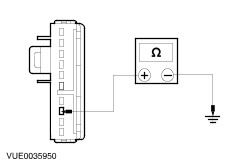
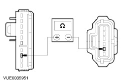
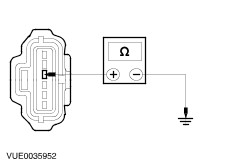
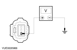
Symptom Chart Symptom Chart | Symptom | Possible Sources | Action | | Incorrect fuel gauge indication | * Fuse(s). * Circuit(s). * Fuel pump module - all except vehicles with diesel engine. * Fuel level sensor - vehicles with diesel engine. * Instrument cluster. | * | | The temperature gauge is inoperative | * Fuse(s). * Circuit(s). * Engine coolant temperature (ECT) sensor. * Instrument cluster. * Powertrain control module (PCM). | * | | The tachometer is inoperative | * Fuse(s). * Circuit(s). * PCM. * Instrument cluster. | * | | The high beam indicator is inoperative/does not operate correctly | * Fuse(s). * Circuit(s). * Instrument cluster. | * | | The low oil pressure warning indicator is inoperative/does not operate correctly | * Fuse(s). * Circuit(s). * Oil pressure switch. * Instrument cluster. | * | | The brake warning indicator is inoperative/does not operate correctly | * Fuse(s). * Circuit(s). * Low brake fluid level switch. * Park brake switch. * Instrument cluster. | * | | The charging system warning indicator is never/always on | * Fuse(s). * Circuit(s). * Charging system. * Instrument cluster. | * | | The glow plug indicator is always on | * Fuse(s). * Circuit(s). * PCM. * Instrument cluster. | * REFER to WDS. | Instrument Cluster Diagnostic Trouble Code (DTC) Index | Self-Diagnostic Mode Displayed DTC | DTC | Description | Action | | 9201 | B1201 | Fuel pump module/fuel level sensor circuit open or short to B+ | GO to Pinpoint Test A. | | 9204 | B1204 | Fuel pump module/fuel level sensor short to ground | GO to Pinpoint Test A. | | 9342 | B1342 | Instrument cluster electronic control unit is defective | REFER to WDS. | | 9317 | B1317 | Battery voltage high (greater than 16V) | REFER to WDS. | | 9318 | B1318 | Battery voltage low (less than 8V) | REFER to WDS. | | 9359 | B1359 | Ignition Run/Acc circuit failure | REFER to WDS. | | A143 | B2143 | Instrument cluster non-volatile memory failure | REFER to WDS. | | 0115 | P0115 | ECT sensor circuit failure | REFER to WDS. | | 5966 | C1966 | Low fuel indication circuit failure short to B+ | REFER to WDS. | | 5967 | C1967 | Low fuel indication circuit failure short to ground | REFER to WDS. | | - | P0656 | Malfunction indicator lamp (MIL) concern | REFER to WDS. | Pinpoint Tests NOTE:Use a digital multimeter for all electrical measurements. | PINPOINT TEST A : INCORRECT FUEL GAUGE INDICATION | | TEST CONDITIONS | DETAILS/RESULTS/ACTIONS | | A1: VERIFY FAULT OF FUEL GAUGE | | | 1 Ignition switch in position II. | | | Does the fuel gauge pointer indicate below the empty (default position)? Yes No | | A2: CHECK CIRCUIT 8-GA7 (WH/RD) FOR SHORT TO GROUND | | | 1 Ignition switch in position 0. | | | 2 Disconnect Instrument Cluster C37a. | | | 3 Measure the resistance between the instrument cluster C37a pin 8, circuit 8-GA7 (WH/RD), harness side and ground. | | | Is the resistance greater than 10,000 ohms? Yes INSTALL a new instrument cluster, REFER to Instrument Cluster - in this section. TEST the system for normal operation. No REPAIR the circuit. TEST the system for normal operation. | | A3: CHECK CIRCUIT 8-GA7 (WH/RD) FOR OPEN | | | 1 Ignition switch in position 0. | | | 2 Disconnect Instrument Cluster C37a. | | | 3 Disconnect Fuel Pump Module - all except vehicles with diesel engine C65. | | | 4 Disconnect Fuel Level Sensor - vehicles with diesel engine C65. | | | 5 Measure the resistance between the instrument cluster C44 pin 8, circuit 8-GA7 (WH/RD), harness side and the following: - fuel pump module - all except vehicles with diesel engine C65 pin 2 circuit 8-GA7 (WH/RD), harness side.
- fuel level sensor - vehicles with diesel engine C65 pin 2 circuit 8-GA7 (WH/RD), harness side.
| | | Is the resistance less than 5 ohms? Yes No REPAIR the circuit. TEST the system for normal operation. | | A4: CHECK CIRCUIT 31-GA7 (BK) FOR OPEN | | | 1 Measure the resistance between the fuel pump module/ fuel level sensor C65 pin 4, circuit 31-GA7 (BK), harness side and ground. | | | Is the resistance less than 5 ohms? Yes On all except vehicles with diesel engine. INSTALL a new fuel pump module. REFER to Section 310-01 Fuel Tank and Lines. TEST the system for normal operation. On vehicles with diesel engine. INSTALL a new fuel level sensor. REFER to Section 310-01 Fuel Tank and Lines. TEST the system for normal operation. No REPAIR the circuit. TEST the system for normal operation. | | PINPOINT TEST B : THE TEMPERATURE GAUGE IS INOPERATIVE | | TEST CONDITIONS | DETAILS/RESULTS/ACTIONS | | B1: CHECK THE ETC SENSOR USING WDS | NOTE:Make sure the engine has reached normal operating temperature and the cooling fan has operated at least once. | | | 1 Use WDS to observe the ECT sensor operation. | | | Is the temperature reading between 70°C and 90°C? Yes No REFER to WDS. | | B2: CHECK THE ETC SENSOR CIRCUIT FOR SHORT TO GROUND | | | 1 Disconnect Instrument Cluster C37a. | | | 2 Disconnect ETC C94. | | | 3 Measure the resistance between the instrument cluster C37a pin 7, circuit 8-GD7 (WH/RD), harness side and ground. | | | Is the resistance greater than 10,000 ohms? Yes No REPAIR circuit 8-GD7 (WH/RD). TEST the system for normal operation. | | B3: CHECK THE ECT SENSOR CIRCUIT FOR OPEN | | | 1 Measure the resistance between the instrument cluster C37a pin 7, circuit 8-GD7 (WH/RD), harness side and ECT C94 pin 1, circuit 8-GD7 (WH/RD), harness side. | | | Is the resistance less than 5 ohms? Yes INSTALL a new instrument cluster. REFER to Instrument Cluster - in this section. TEST the system for normal operation. No REPAIR circuit 8-GD7 (WH/RD). TEST the system for normal operation. | | PINPOINT TEST C : THE TACHOMETER IS INOPERATIVE | | TEST CONDITIONS | DETAILS/RESULTS/ACTIONS | | C1: CHECK THE TACHOMETER CIRCUIT FOR SHORT TO GROUND | | | 1 Disconnect Instrument Cluster C37b. | | | 2 Disconnect PCM C43. | | | 3 Measure the resistance between the instrument cluster C37b pin 9, circuit 8-GB10B (WH/BK), harness side and ground. | | | Is the resistance greater than 10,000 ohms? Yes No REPAIR circuit 8-GB10B (WH/BK). TEST the system for normal operation. | | C2: CHECK THE TACHOMETER CIRCUIT FOR SHORT TO BATTERY POSITIVE | | | 1 Measure the voltage between the instrument cluster C37b pin 9, circuit 8-GB10B (WH/BK), harness side and ground. | | | Is any voltage present? Yes REPAIR the short to battery positive. For additional information. REFER to the wiring diagrams. TEST the system for normal operation. No | | C3: CHECK CIRCUIT 8-GB10 FOR OPEN | | | 1 Measure the resistance between the instrument cluster C37b pin 9, circuit 8-GB10B (WH/BK), harness side and PCM C43 pin 4, circuit 8-GB10 (WH/BK), harness side | | | Is the resistance less than 5 ohms? Yes No REPAIR the circuit. TEST the system for normal operation. | | C4: CHECK THE TACHOMETER INPUT SIGNAL USING WDS OSCILLOSCOPE | | | 1 Connect PCM C43. | | | 2 Using WDS oscilloscope, measure the tachometer input signal frequency between the instrument cluster C44 pin 21, circuit 8-GB10, (WH/BK), harness side and ground. | | | Is the frequency pattern within working parameters? Yes INSTALL a new instrument cluster. REFER to Instrument Cluster - in this section. TEST the system for normal operation. No | | PINPOINT TEST D : THE HIGH BEAM INDICATOR IS INOPERATIVE/DOES NOT OPERATE CORRECTLY | | TEST CONDITIONS | DETAILS/RESULTS/ACTIONS | | D1: CHECK OPERATION OF HIGH BEAM | | | 1 Ignition switch in position II. | | | 2 Place the multifunction switch in the HIGH beam position. | | | Do the headlamps illuminate? Yes No | | D2: CHECK FOR VOLTAGE ON CIRCUIT 14-LE11 (VT/WH) | | | 1 Ignition switch in position 0. | | | 2 Disconnect Instrument Cluster C37a. | | | 3 Ignition switch in position II. | | | 4 Measure the voltage between the instrument cluster C37a pin 2, circuit 14S-LE11 (VT/WH), harness side and ground. | | | Is the voltage greater than 10 volts? Yes No REPAIR the circuit. TEST the system for normal operation. | | D3: CHECK CIRCUIT 31-WC43A (BK) FOR GROUND | | | 1 Ignition switch in position 0. | | | 2 Disconnect Instrument Cluster C37b. | | | 3 Measure the resistance between the instrument cluster C37b pin 14, circuit 31-WC43A (BK), harness side and ground. | | | Is the resistance less than 5 ohms? Yes INSTALL a new instrument cluster. REFER to Instrument Cluster - in this section. TEST the system for normal operation. No REPAIR the circuit. TEST the system for normal operation. | | PINPOINT TEST E : THE LOW OIL PRESSURE WARNING INDICATOR IS INOPERATIVE/DOES NOT OPERATE CORRECTLY | | TEST CONDITIONS | DETAILS/RESULTS/ACTIONS | | E1: TEST OPERATION OF LOW OIL PRESSURE WARNING INDICATOR | | | 1 Disconnect Oil Pressure Switch C93. | | | 2 Connect a fused jumper wire between the oil pressure switch C93 pin 1, harness side and ground. | | | 3 Ignition switch in position II. | | | 4 Observe the low oil pressure warning indicator. | | | Does the low oil pressure warning indicator illuminate? Yes INSTALL a new oil pressure switch. TEST the system for normal operation. No | | E2: CHECK THE LOW OIL PRESSURE WARNING INDICATOR CIRCUIT | | | 1 Ignition switch in position 0. | | | 2 Disconnect Instrument Cluster C37b. | | | 3 Measure the resistance between the instrument cluster C37b pin 11, circuit 31S-WD9 (BK/GN), harness side and oil pressure switch C93 pin 1, harness side. | | | Is the resistance less than 5 ohms? Yes INSTALL a new instrument cluster. REFER to Instrument Cluster - in this section. TEST the system for normal operation. No REPAIR circuit 31S-WD9 (BN/GN). TEST the system for normal operation. | | PINPOINT TEST F : THE BRAKE WARNING INDICATOR IS INOPERATIVE/DOES NOT OPERATE CORRECTLY | | TEST CONDITIONS | DETAILS/RESULTS/ACTIONS | | F1: TEST OPERATION OF BRAKE WARNING INDICATOR CIRCUITS | | | 1 Disconnect Instrument Cluster C37a - 1.6L Duratec. | | | 2 Disconnect Instrument Cluster C37b - 1.3L Duratec/1.8L Endura DE. | | | 3 Measure the resistance between the instrument cluster C37a pin 4 (1.6L Duratec), circuit 31S-WB7 (BK/BU), harness side and ground. | | | 4 Measure the resistance between the instrument cluster C37b pin 12 (1.3L Duratec/1.8L Endura DE), circuit 31S-WB7 (BK/BU), harness side and ground. | | | 5 Apply the hand brake and press the brake fluid level indicator test button. | | | Is the resistance less than 5 ohms? Yes INSTALL a new instrument cluster. REFER to Instrument Cluster - in this section. TEST the system for normal operation. No | | F2: CHECK OPERATION OF BRAKE WARNING INDICATOR | | | 1 Connect Instrument Cluster C37a - 1.6L Duratec. | | | 2 Connect Instrument Cluster C37b - 1.3L Duratec/1.8L Endura DE. | | | 3 Disconnect Brake Fluid Level Switch C64. | | | 4 Connect a fused jumper wire between the brake fluid level switch C64 pin 2, circuit 31S-WB7 (BK/BU), harness side and ground. | | | Does the brake warning indicator illuminate? Yes INSTALL a new brake fluid level switch. TEST the system for normal operation. No REPAIR the circuit 31S-WB7 (BK/BU). TEST the system for normal operation. | | PINPOINT TEST G : THE CHARGING SYSTEM WARNING INDICATOR IS NEVER/ALWAYS ON | | TEST CONDITIONS | DETAILS/RESULTS/ACTIONS | | G1: TEST OPERATION OF CHARGING SYSTEM WARNING INDICATOR | | | 1 Ignition switch in position II. | | | 2 Observe the charging system warning indicator. | | | Does the charging system warning indicator illuminate? Yes No | | G2: CHECK THE CHARGING SYSTEM WARNING INDICATOR CIRCUIT | | | 1 Ignition switch in position 0. | | | 2 Disconnect Generator C22b. | | | 3 Ignition switch in position II. | | | 4 Observe the charging system warning indicator. | | | Does the charging system warning indicator illuminate? Yes Vehicles with 1.3L Duratec/1.8L Endura DE. REPAIR the circuit 64-BA9A (BU/BK). TEST the system for normal operation. Vehicles with 1.6L Duratec. REPAIR the circuit 64-BA9 (BU/BK). TEST the system for normal operation. No Vehicles with 1.3L Duratec/1.8L Endura DE. GO to G3. | | G3: CHECK THE CHARGING SYSTEM WARNING INDICATOR CIRCUIT | | | 1 Ignition switch in position 0. | | | 2 Disconnect Generator C22b. | | | 3 Ignition switch in position II. | | | 4 Measure the voltage between the generator C22b pin 1, circuit 64-BA9A (BU/BK), harness side and ground. | | | Is the voltage greater than 10 volts? Yes No | | G4: CHECK THE CHARGING SYSTEM WARNING INDICATOR CIRCUIT FOR OPEN | | | 1 Ignition switch in position 0. | | | 2 Disconnect Instrument Cluster C37b. | | | 3 Measure the resistance between the instrument cluster C37b pin 10, circuit 64-BA9A (BU/BK), harness side and generator C22b pin 1, circuit 64-BA9 (BU/BK), harness side. | | | Is the resistance less than 5 ohms? Yes INSTALL a new instrument cluster. REFER to Instrument Cluster - in this section. TEST the system for normal operation. No REPAIR the circuit 64-BA9 (BU/BK) or circuit 64-BA9A (BU/BK) as necessary. TEST the system for normal operation. | | G5: CHECK THE CHARGING SYSTEM WARNING INDICATOR CIRCUIT | | | 1 Ignition switch in position 0. | | | 2 Disconnect Generator C22b. | | | 3 Ignition switch in position II. | | | 4 Measure the voltage between the generator C22b pin 1, circuit 64-BA9 (BU/BK), harness side and ground. | | | Is the voltage greater than 10 volts? Yes No | | G6: CHECK THE CHARGING SYSTEM WARNING INDICATOR CIRCUIT FOR OPEN | | | 1 Ignition switch in position 0. | | | 2 Disconnect Instrument Cluster C37b. | | | 3 Measure the resistance between the instrument cluster C37b pin 10, circuit 64-BA9 (BU/BK), harness side and generator C22b pin 1, circuit 64-BA9 (BU/BK), harness side. | | | Is the resistance less than 5 ohms? Yes INSTALL a new instrument cluster. REFER to Instrument Cluster - in this section. TEST the system for normal operation. No REPAIR the circuit 64-BA9 (BU/BK). TEST the system for normal operation. | |