| Description and Operation The headlamp unit consists of two compartments. The turn signal and the high and low beam, side lights are contained in two separate compartments. High and low beams each use a HB3LL bulb. Both bulbs are switched on for high beam. NOTE:Only use original equipment bulbs in service. The turn signal lamp consists of an orange lens and a clear bulb. Headlamp System The headlamp system consists of: - two headlamp assemblies,
- a multifunction switch on the steering column,
- low beam relay,
- high beam relay,
- turn signal and low beam switch,
- high beam display,
- wiring harness,
- fuses.
The voltage to the multifunction switch is supplied through fuse F9 and the ignition switch. Fuse F9 is located in the central junction box (CJB). When the headlamps are switched on, a voltage is supplied to the high and low beam switch and to the coil of the low beam relay. The low beam relay is located in the CJB. CAUTION:The voltage supply to the low beam relay, Pin 5, is not fused. If the main and low beam switch is set to ”low beam", then a voltage is supplied through the low beam relay to the low beam bulb. The left and right-hand low beams are fused separately through fuses F10 and F11. These fuses are located in the CJB. CAUTION:The voltage supply to the high beam relay, Pin 5, is not fused. If the high and low beam switch is set to ”high beam", then a voltage is supplied via the high beam relay to the high beam bulb. The left and right-hand high beams are fused separately through fuses F21 and F22. These fuses are located in the CJB. Multifunction switch The multifunction switch has the following settings for the exterior lights: - off,
- side lamps,
- driving lamps, set to either
- headlamp flash.
If the multifunction switch is set to ”side lamps", then a voltage is supplied to the front and rear side lamps, as well as to the license plate lamp. Low beam and high beam can only be switched on if the ignition is switched on. If the switch is set to ”low beam", the low beam relay is activated first, which then switches the voltage to the bulbs. If the switch is set to ”high beam" or ”headlamp flash", the high beam relay is activated first, which then switches the voltage to the bulbs. Side lamps - The voltage to the side lamps is switched through the multifunction switch on the left-hand side of the steering column.
- The circuits for left and right-hand side are fused separately through fuses F6 and F7 in the CJB.
- The lamps are in operation when the switch is set to ”side lamps" or ”driving lamps".
License plate lamps There is one license plate lamp to illuminate the license plate. The lamp is supplied with a voltage through fuse F7. The license plate lamp illuminates when the switch is set to ”side lamps" or ”driving lamps". Stoplamp switch The stoplamp switch is installed underneath the instrument panel on the brake pedal bracket. It switches the voltage to the stoplamps through fuse F13 in the CJB. Reversing lamps The reversing lamp system consists of: - reversing lamp bulb,
- reversing lamp switch,
- wiring harness,
- fuse F13.
The reversing lamp switch supplies the reversing lamps with voltage. This circuit is fused through fuse F13 in the CJB. Stoplamps - The stoplamps are integrated in the rear lamp assemblies.
- The stoplamp switch supplies the stoplamps with voltage.
Turn signal and hazard warning lamps The turn signal and hazard warning lamp system consists of: - turn signal switch (included in the multifunction switch on the steering column),
- turn signal relay,
- turn signal lamps,
- turn signal and hazard warning lamp indicator in the instrument cluster,
- wiring harness,
- fuses F5 and F17.
The turn signal relay is supplied with voltage through fuse F17 in the CJB and the turnsignal lamp switch. Hazard warning lamp switch - The hazard warning lamp switch is incorporated in the multifunction switch on the steering column. It is located on top of the steering column shroud.
- When the hazard warning lamp switch is switched on all four turn signal lamps and the hazard warning lamp indicator in the instrument cluster are supplied with a voltage through fuse F5 in the CJB and the turn signal relay.
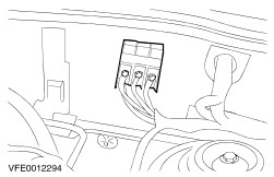
Turn signal relay The turn signal relay operates electronically and is plugged into the multifunction switch. Fuses and Relays Battery junction box (BJB) Central junction box (CJB)- front view, fuses 1 - Fuse F12 - multifunction switch, windshield wiper motor, wiper relay 2 - Fuse F13 - stoplamp, transmission switch, instrument cluster illumination, heating 3 - Fuse F15 - multifunction switch 4 - Fuse F17 - multifunction switch 5 - Fuse F21 - headlamp LH, instrument cluster illumination 9 - Fuse F9 - multifunction switch 10 - Fuse F7 - front parking lamp RH, licence plate lamp, rear lamp assembly RH 11 - Fuse F6 - front parking lamp LH, rear lamp assembly LH, front parking lamp LH, instrument cluster illumination, radio, heating 12 - Fuse F5 - multifunction switch Central Junction Box (CJB)- top view 8 - Fuel pump relay (petrol) Multifunction switch 1 - Connection point for connector C15a 2 - Connection point for connector C15b |