| PINPOINT TEST C : THE DEFROST SYSTEM IS INOPERATIVE |
| TEST CONDITIONS | DETAILS/RESULTS/ACTIONS |
| C1: CHECK THE OPERATION OF THE HEATED REAR WINDOW RELAY |
| | 1 Ignition switch in position II. |
| | 2 Operate the heated rear window control switch. |
| | Does the heated rear window relay click? Yes No |
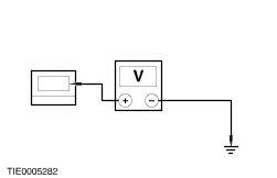
| C2: CHECK FOR VOLTAGE TO THE HEATED REAR WINDOW |
| | 1 Ignition switch in position 0. |
| | 2 Disconnect Heated Rear Window C125. |
| | 3 Ignition switch in position II. |
| | 4 Operate the heated rear window control switch. |
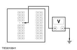
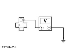
| | 5 Measure the voltage between the heated rear window C125 pin 1, circuit 14S-HB19 (VT/BL), harness side and ground. |
| | Is the voltage greater than 10 volts? Yes No |
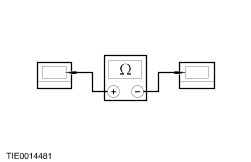
| C3: CHECK THE HEATED REAR WINDOW GROUND CIRCUIT |
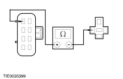
| | 1 Measure the resistance between the heated rear window C125, component side and ground. |
| | Is the resistance less than 5 ohms? Yes No REPAIR the heated windshield ground circuit. TEST the system for normal operation. |
| C4: CHECK THE CONTINUITY OF THE HEATED REAR WINDOW GRID WIRES |
| | 1 Measure the resistance between the heated rear window C125, component side and the heated rear window ground, component side. |
| | Is the resistance less than 5 ohms? Yes VERIFY the customer concern. No INSTALL a new heated rear window. TEST the system for normal operation. |
| C5: CHECK THE HEATED REAR WINDOW CONTROL SWITCH LED |
| | 1 Operate the headlamp control switch. |
| | Does the heated rear window control switch location lamp illuminate? Yes No |
| C6: CHECK THE HEATED REAR WINDOW RELAY GROUND CIRCUIT |
| | 1 Ignition switch in position 0. |
| | 2 Disconnect Heated Rear Window Relay C123. |
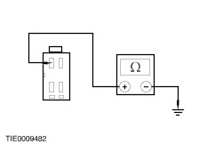
| | 3 Measure the resistance between the heated rear window relay C123 pin 1, circuit 31-DB3 (BK), harness side and ground. |
| | Is the resistance less than 5 ohms? Yes No REPAIR circuit 31-DB3 (BK). TEST the system for normal operation. |
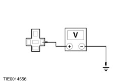
| C7: CHECK FOR VOLTAGE TO THE HEATED REAR WINDOW RELAY |
| | 1 Ignition switch in position II. |
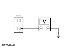
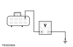
| | 2 Measure the voltage between the heated rear window relay C123 pin 5, circuit 14-HB20 (VT/BK), harness side and ground. |
| | Is the voltage greater than 10 volts? Yes No REPAIR circuit 14-HB20 (VT/BK). TEST the system for normal operation. |
| C8: CHECK CIRCUIT 31S-HB21 (BK/RD) FOR CONTINUITY |
| | 1 Ignition switch in position 0. |
| | 2 Disconnect Heated Rear Window Control Switch C124. |
| | 3 Measure the resistance between the heated rear window control switch C124 pin 1, circuit 31S-HB21 (BK/RD), harness side and the heated rear window relay C123 pin 2, circuit 31S-HB21 (BK/RD), harness side. |
| | Is the resistance less than 5 ohms? Yes Install a new heated rear window relay. TEST the system for normal operation. No REPAIR circuit 31S-HB21 (BK/RD). TEST the system for normal operation. |
| C9: CHECK CIRCUIT 14-HB19 (VT/BU) FOR CONTINUITY |
| | 1 Ignition switch in position 0. |
| | 2 Disconnect Heated Rear Window Relay C123. |
| | 3 Measure the resistance between the heated rear window relay C123 pin 4, circuit 14-HB19 (VT/BU), harness side and the heated rear window C125 pin 1, circuit 14-HB19 (VT/BU), harness side. |
| | Is the resistance less than 5 ohms? Yes No REPAIR circuit 14-HB19 (VT/BU). TEST the system for normal operation. |
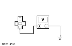
| C10: CHECK FOR VOLTAGE TO THE HEATED REAR WINDOW RELAY |
| | 1 Ignition switch in position II. |
| | 2 Measure the voltage between the heated rear window relay C123 pin 3, circuit 29-HB24 (OG/YE), harness side and ground. |
| | Is the voltage greater than 10 volts? Yes Install a new heated rear window relay. TEST the system for normal operation. No REPAIR circuit 29-HB24 (OG/YE). TEST the system for normal operation. |
| C11: CHECK FOR VOLTAGE TO THE HEATED REAR WINDOW CONTROL SWITCH |
| | 1 Ignition switch in position 0. |
| | 2 Disconnect Heated Rear Window Control Switch C124. |
| | 3 Ignition switch in position II. |
| | 4 Measure the voltage between the heated rear window control switch C124 pin 8, circuit 29S-LA43 (OG/YE), harness side and ground. |
| | Is the voltage greater than 10 volts? Yes No REPAIR circuit 29S-LA43 (OG/YE). TEST the system for normal operation. |
| C12: CHECK THE HEATED REAR WINDOW CONTROL SWITCH GROUND CIRCUIT |
| | 1 Ignition switch in position 0. |
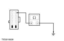
| | 2 Measure the resistance between the heated rear window control switch C124 pin 2, circuit 31-HB22 (BK), harness side and ground. |
| | Is the resistance less than 5 ohms? Yes No REPAIR circuit 31-HB22 (BK). TEST the system for normal operation. |
| C13: CHECK THE HEATED REAR WINDOW CONTROL SWITCH GROUND CIRCUIT |
| | 1 Measure the resistance between the heated rear window control switch C124 pin 4, circuit 31-HB31 (BK), harness side and ground. |
| | Is the resistance less than 5 ohms? Yes Install a new heated rear window control switch. TEST the system for normal operation. No REPAIR circuit 31-HB31 (BK). TEST the system for normal operation. |