| Description and Operation WARNING:To avoid accidental deployment and possible injury, the air bag system backup power supply must be depleted before repairing any climate control components. To deplete the backup power supply, disconnect the battery positive cable and wait one minute. Failure to follow these instructions may result in personal injury. WARNING:Carbon monoxide is colorless, odorless and dangerous. If it is necessary to operate the engine with vehicle in a closed area such as a garage, always use an exhaust collector to vent the exhaust gases outside the closed area. Failure to follow these instructions may result in personal injury. WARNING:R-134a is classified as a safe refrigerant, but misuse can make it dangerous. The following precautions must be observed. Failure to follow these instructions may result in personal injury. - Always wear safety goggles when repairing an air conditioning system.
- Avoid contact with liquid refrigerant R-134a. R-134a vaporizes at approximately -25°C (-13°F) under atmospheric pressure and it will freeze skin tissue.
- Never allow refrigerant R-134a gas to escape in quantity in an occupied space. R-134a is non-toxic, but it will displace the oxygen needed to support life.
- Do not allow any portion of the charged air conditioning system to become too hot. The pressure in an air conditioning system rises as the temperature rises and temperatures of approximately 85°C (185°F) can be dangerous.
- Allow the engine to cool sufficiently prior to carrying out maintenance or serious burns and injury can occur.
CAUTION:To avoid damaging the vehicle or A/C components, the following precautions must be observed: - The A/C refrigerant of all vehicles must be identified and analyzed prior to refrigerant charging. Failure to do so can contaminate the shop bulk refrigerant and other vehicles.
- Do not add R-12 refrigerant to an A/C system that requires the use of R-134a refrigerant. These two types of refrigerant must never be mixed. Doing so can damage the A/C system.
- Charge the A/C system with the engine running only at the low-pressure side to prevent refrigerant slugging from damaging the A/C compressor.
- Use only R-134a refrigerant. Due to environmental concerns, when the air conditioning system is drained, the refrigerant must be collected using refrigerant recovery/recycling equipment. R-134a must never be removed without the appropriate equipment or released into the atmosphere. Use of a recovery machine dedicated to R-134a is necessary to reduce the possibility of oil and refrigerant incompatibility concerns. Refer to the instructions provided by the equipment manufacturer when removing refrigerant from or charging the air conditioning system.
- Refrigerant R-134a must not be mixed with air for leak testing or used with air for any other purpose above atmospheric pressure. R-134a is combustible when mixed with high concentrations of air and at higher pressures.
- A number of manufacturers are producing refrigerant products that are described as direct substitutes for refrigerant R-134a. The use of any unauthorized substitute refrigerant can severely damage the A/C components. If repair is necessary, use only new or recycled refrigerant R-134a.
CAUTION:To avoid contamination of the A/C system: - Keep service tools and the work area clean.
- Never open or loosen a connection before discharging the system.
- When loosening a connection, if any residual pressure is evident, allow it to leak out before opening the fitting.
- Evacuate a system that has been opened to install a new component or a system that has discharged through leakage before charging.
- Seal open fittings with a cap or plug immediately after disconnecting a component from the system.
- Clean the outside of the fittings thoroughly before disconnecting a component from the system.
- Do not remove the sealing caps from a new component until ready to install.
- Refrigerant oil will absorb moisture from the atmosphere if left uncapped. Do not open an oil container until ready to use, and install the cap immediately after using. Store the oil in a clean, moisture-free container.
- Install a new O-ring seal before connecting an open fitting. Coat the fitting and O-ring seal with refrigerant oil before connecting.
- When installing a refrigerant line, avoid sharp bends. Position the line away from the exhaust or any sharp edges that can chafe the line.
- Tighten threaded fittings only to specifications. The steel and aluminum fittings used in the refrigerant system will not tolerate overtightening.
- When disconnecting a fitting, use a wrench on both halves of the fitting to prevent twisting of the refrigerant lines or tubes.
- Do not open a refrigerant system or uncap a new component unless it is as close as possible to room temperature. This will prevent condensation from forming inside a component that is cooler than the surrounding air.
Climate Control Operation — RHD The RHD temperature control system electrical components are as follows: - Climate control assembly.
- Actuator assembly.
- A/C cycling switch.
- A/C pressure cut-off switch.
- Powertrain control module.
- A/C relay.
- A/C clutch field coil.
- Blower relay.
- Blower motor.
- Fan motor.
Climate Control System — LHD The LHD climate control system electrical components are as follows: - Climate control panel
- A/C cycling switch
- A/C pressure cut-off switch
- Powertrain control module
- A/C relay
- A/C clutch field coil
- Heater blower motor resistor
- Blower relay
- Blower motor
- Fan motor
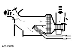
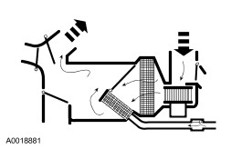
PANEL When PANEL is selected: - The air inlet door, with no vacuum being applied, will block recirculated air and admit outside air. From there, air flows through the system to the instrument panel A/C registers.
- The panel vent airflow door is at partial vacuum to direct airflow to the panel vent ducts.
- The defrost door is at full vacuum and defrost airflow door is at no vacuum, closing off airflow to the windshield defroster hose nozzles and floor ducts.
- The temperature setting can be changed manually to heat the air but air cannot be cooled below the outside temperature.
- The A/C compressor will be disabled when VENT is selected.
- The blower motor is on.
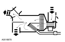
PANEL/FLOOR When PANEL/FLOOR is selected: - The air inlet duct door is set at no vacuum, blocking the recirculation passage and admitting outside air.
- The floor airflow door is in the full vacuum position, and the panel airflow door is in the full vacuum position allowing airflow to blend between the panel vents and the floor ducts.
- The defrost airflow door is at full vacuum, closing off airflow to the windshield defroster hose nozzle and directing airflow to the heater outlet floor duct.
- The A/C compressor will be enabled when PANEL/FLOOR is selected.
- The blower motor is on.
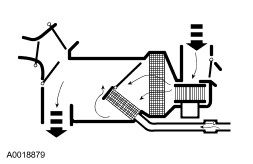
FLOOR When FLOOR is selected: - The air inlet duct door is in the no vacuum position, blocking recirculation air and admitting outside air.
- The floor airflow door is at the full vacuum position, opening the door and allowing airflow through the floor ducts.
- The defrost airflow door and the panel airflow door are in the no vacuum position, closing off airflow to the windshield defroster hose nozzles and panel registers.
- The temperature control can be positioned to mix air flowing through and around the heater core to achieve the selected temperature level.
- The A/C compressor will be disabled when FLOOR is selected.
- The blower motor is on.
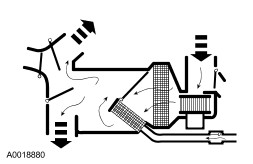
FLOOR/DEFROST When FLOOR/DEFROST is selected: - The air inlet duct door is in the no vacuum position blocking recirculation air and admitting outside air.
- The floor airflow door is at full vacuum allowing air to flow through the floor ducts.
- The defrost airflow is in the no vacuum position, allowing airflow to both the windshield defroster hose nozzle and side window demister hose nozzle ducts.
- The panel vent airflow door is in the no vacuum position.
- The A/C compressor will be enabled when FLOOR/DEFROST is selected to dehumidify the air and reduce windshield fogging.
- The blower motor is on.
DEFROST When DEFROST is selected: - The air inlet duct door is in the no vacuum position, admitting outside air.
- The defrost airflow door is at no vacuum, directing the airflow to the windshield through the defroster ducts and the side windows through the demister ducts.
- The panel airflow door and the floor airflow door are in the no vacuum position so that most of the incoming air is directed to the windshield defroster hose nozzle. There is also airflow to the side window demister and hose.
- The temperature control knob setting will determine the amount of air that is directed through the heater core and the amount that bypasses the heater core.
- The A/C compressor will be enabled when DEFROST is selected to dehumidify the air and reduce windshield fogging.
- The blower motor is on.
|