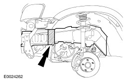
| Description and Operation Introduction Body-relevant subsections of the Ford Maverick predecessor model have been modified in line with model year 2001. The main changes concern the unitary body structure, front side members and front bolt-on crossmember. Additional plastic parts have been integrated in the area of the attachments. Their main purpose is to protect the exposed areas of the body outer skin and to help prevent paint damage (wheel arch, doors). A plastic panel is used as a "filler" between the bumper panel and the rear crossmember. Construction features The Ford Maverick 2001 is designed as a complete unitary body without specific frame construction. The entire "frame section" is integrated in the body floor pan. In the front axle subsection, the side members are designed in "centreboard form" Structure of the front side member The modified design of the front side members has mainly optimised crash compatibility. The strength and deformation properties are calculated based on the latest technological findings. The same applies in the case of the design and the styling. There are intentional yield points attached in the deformation zone (rectangular section). The rectangular section runs into a centreboard-shaped section in which additional reinforcements are integrated. If crash impact occurs, the front bolt-on crossmember absorbs a large proportion of the energy. The side members are slightly deformed in the front-most area of the intentional yield points only. The remainder of the energy is dissipated without causing further deformation in the side member. Front side member 2 - Intentional yield points 4 - Transition to centreboard section Side member and crossmember connection The joint which connects the front side member with the crossmember is very easy to repair. The separate junction plates (U-sections) simply have to be exchanged in the event of repair. The permitted oversize bore tolerance allows the junction plates to freely move in longitudinal direction and the crossmembers to freely move in transverse direction, thus making it easier to adjust the bumper. Side member and crossmember connection 1 - Retaining bolts for junction plate with elongated holes Dimensional stability Always check the dimensional stability of the side members at an appropriate degree of deformation. Partial section repair If required, the front side member can undergo partial section repair. Cutting is only permitted inside the rectangular section area and outside the intentional yield point area. Front side member cut area Rear side member and crossmember The rear side members (cap sections) are welded to the boot floor. Rear impact forces are transferred to the side members via the rear crossmember (crash element). An additional crash box is located between the rear ends of the side members in each case. The cross members are bolted onto the crash box. Rear side member and crossmember High-strength steel parts More high-strength steel panels are used on the Maverick 2001 body. NOTE:The working methods outlined in Body Manual I (501-25A) must be observed in all repair work. Overview of parts, front end 1 - Galvanised steel panels 2 - High-strength and galvanised steel panels Overview of parts, side view and roof The high-strength steel parts are indicated with arrows. Overview of parts, floor pan 1 - High-strength steel parts 2 - Galvanised steel panels 3 - High-strength and galvanised steel panels |