| Removal and Installation Special Tool(s) | | Alignment Pins, Subframe 205-316 (15-097A) | | | Separator, Ball Joint 211-020 (13-006) | | | Wrench, Steering Gear 211-186 (13-013) | | | Socket Wrench, Union Nut 211-187 (13-014) | | | Expander, Teflon Seal 211-188 (13-015) | General Equipment Removal All vehicles | | -
NOTE:Make sure the road wheels are in the straight ahead position. Center the steering wheel and lock in position. | | | -
Detach the carpet retaining clip. | | | -
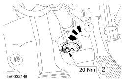
Detach the steering column shaft from the steering column flexible coupling. - Discard the retaining bolt.
- Rotate the clamp plate.
| | | -
Remove the engine undershield (if equipped). | | | -
Remove the radiator splash shield. | Vehicles with 2.5L engine | | -
Detach the exhaust pipe flexible coupling. - Discard the gasket and nuts
| Vehicles with 1.6L, 1.8L or 2.0L engine | | -
Detach the catalytic converter. - Discard the gasket and nuts
| Vehicles with manual transmission | | -
Remove the rear support insulator center bolt. - Loosen the mounting bolts.
- Remove the rear support insulator center bolt.
| Vehicles with automatic transmission | | -
Detach the rear support insulator. - Remove the center bolt.
- Remove the mounting bolts.
| All vehicles | | -
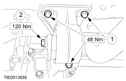
Loosen the front support insulator center bolt. - Loosen the mounting nuts.
- Loosen the front support insulator center bolt.
| | | -
CAUTION:Leave the retaining nuts in place to protect the ball joint studs when releasing the tie-rod ends. Loosen the tie-rod end retaining nuts. | | | -
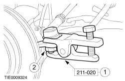
CAUTION:When the tie-rod ends are separated, the ball joint seals should be protected to prevent damage. Using the special tool detach the tie-rod ends from the wheel knuckles. - Release the tie-rod ends.
- Remove and discard the retaining nuts.
| | | -
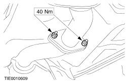
CAUTION:When disconnecting the connecting links, insert a suitable tool between the mounting bracket and connecting link ball joint, to prevent damage to the connecting link ball joint boot. Disconnect the connecting links. - Insert the suitable tool.
- Remove the nuts.
- Disconnect the connecting links.
| | | -
Remove the driver side fender splash guards. | | | -
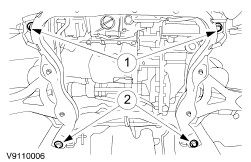
Lower the front subframe assembly to gain access to the steering gear. - Loosen the front subframe assembly retaining bolts two complete turns.
- Remove the front subframe assembly rear retaining bolts.
| Vehicles with automatic transmission | | -
Remove the rear support insulator. | Vehicles built up to 12/1999 | | -
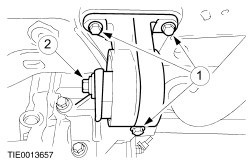
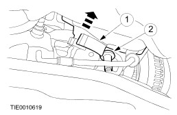
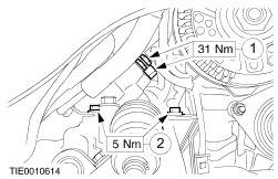
CAUTION:Whenever the steering gear unions are disconnected the steering gear valve body ports should be plugged to prevent dirt ingress. Disconnect the power steering lines from the steering gear. - Remove the support bracket bolts.
- Detach the power steering lines.
- Allow the fluid to drain into a suitable container.
| Left-hand drive vehicles | | -
CAUTION:Whenever the steering gear unions are disconnected the steering gear valve body ports should be plugged to prevent dirt ingress. Using the special tool, disconnect the power steering lines from the steering gear. - Allow the fluid to drain into a suitable container.
| Vehicles built 12/1999 onwards | | -
CAUTION:Whenever the steering gear unions are disconnected the steering gear valve body ports should be plugged to prevent dirt ingress. Disconnect the power steering lines from the steering gear. - Allow the fluid to drain into a suitable container.
| Right-hand drive vehicles | | -
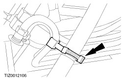
Detach the resonance pipe from the power steering line. | Left-hand drive vehicles | | -
Detach the resonance pipe from the power steering line. | All vehicles | | -
Remove the steering gear cover plate (if equipped). | | | -
Remove the steering column flexible coupling. - Discard the retaining bolt.
| | | -
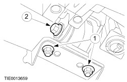
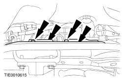
NOTE:The mounting bolt under the bulkhead floor seal will not come fully out at this point. Using the special tool remove the steering gear mounting bolts. | | | -
Remove the steering gear to bulkhead floor seal. - Remove the floor seal.
- Remove the mounting bolt.
| | | -
CAUTION:Make sure that the pressure check valve does not fall out of the valve body pressure port when the steering gear assembly is being removed. Remove the steering gear assembly through the wheelhouse. | Installation All Vehicles | | -
CAUTION:Make sure the pressure check valve is installed correctly. Install the pressure check valve. | | | -
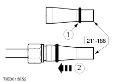
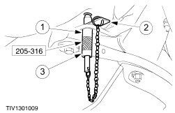
NOTE:If a new steering gear assembly is being installed. The unions supplied fitted to the new steering gear should be removed and saved for further use. Using the special tool, install the new union O-ring seals - Push the new O-ring seal onto the special tool.
- Locate the special tool onto the union and push on the new O-ring seal.
| | | -
Using the special tool, install the steering gear. | | | -
Install the steering gear to bulkhead floor seal. | | | -
WARNING:Install a new steering column flexible coupling retaining bolt. Failure to follow this instruction may result in personal injury. Install the steering column flexible coupling. | | | -
Install the steering gear cover plate (if equipped). | Vehicles built 12/1999 onwards | | -
Connect the steering gear lines to the steering gear. | Right-hand drive vehicles | | -
Attach the resonance pipe to the power steering line. | Left-hand drive vehicles | | -
Attach the resonance pipe to the power steering line. | Vehicles built up to 12/1999 | | -
Connect the steering gear lines to the steering gear. - Connect the steering gear lines.
- Install the support bracket bolts.
| Left-hand drive vehicles | | -
Using the special tool, connect the power steering lines to the steering gear. | Vehicles with automatic transmission | | -
Loosely install the rear support insulator. | All vehicles | | -
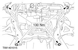
Using the special tools, align the front subframe assembly. - Push the alignment pins through the subframe aligning holes.
- Slide the locking plate into the locking grooves.
- Tighten the alignment pin sleeves.
| | | -
Install the front subframe assembly bolts. | | | -
Remove the alignment pins. | Vehicles with manual transmission | | -
Centralize the rear support insulator. - Centralize the rear support insulator and tighten the mounting bolts.
- Install the rear support insulator center bolt.
| Vehicles with automatic transmission | | -
Centralize the rear support insulator. - Centralize the rear support insulator and install the mounting bolts.
- Install the rear support insulator center bolt.
| All vehicles | | -
Centralize the front support insulator. - Centralize the front support insulator and tighten the mounting nuts.
- Tighten the front support insulator center bolt.
| Vehicles with 2.5L engine | | -
NOTE:Install a new gasket and nuts. Attach the exhaust pipe flexible coupling. | Vehicles with 1.6L, 1.8L or 2.0L engine | | -
NOTE:Install a new gasket and nuts. Attach the catalytic converter. | All vehicles | | -
Install the radiator splash shield. | | | -
Install the engine undershield (if equipped). | | | -
CAUTION:When installing the connecting links, insert a suitable tool between the mounting bracket and connecting link ball joint, to prevent damage to the connecting link ball joint boot. Connect the connecting links. - Connect the connecting links.
- Insert the suitable tool.
- Install the nuts.
| | | -
WARNING:Install new tie-rod end retaining nuts. Failure to follow this instruction, may result in personal injury. Attach the tie-rod ends to the wheel knuckles. | | | -
Install the driver side fender splash guards. | | | -
NOTE:Before lowering the vehicle make sure the road wheels are in the straight ahead position. Install the driver side front wheel and tire. For additional information, refer to Section 204-04 Wheels and Tires. | | | -
WARNING:Install a new steering column to steering column flexible coupling retaining bolt. Failure to follow this instruction may result in personal injury. Connect the steering column shaft to the steering column flexible coupling. - Rotate the clamp plate.
- Install the retaining bolt.
| | | -
Attach the carpet retaining clip. | |