| Disassembly Special Tool(s) | | Slide hammer 205-047 (15011) | | | Universal flange holding wrench 205-072 (15030A) | | | Mounting bracket 303-435-04 (21064) | | | Immobilizing tool, flywheel 303-254 (21135) | | | Mounting plate 303-435-12 (21150A) | | | Pliers, spark plug connectors 303-622 (21226) | | | Remover, oil pan 303-633 (21227) | General Equipment Wooden blocks Retaining straps Workshop hoist Disassembly | | -
General notes. - The engine remains suspended in the workshop hoist until the assembly stand can be attached .
- If the engine needs to be temporarily unhooked from the hoist whilst positioned on the assembly table, secure it with retaining straps .
| | | -
Disconnect the plugs from the camshaft position (CMP) sensor and the engine coolant temperature (ECT) sensor. - Unclip the cable from the EI coil.
| | | -
Disconnect the oil pressure switch plug and the knock sensor (KS) plug. | | | -
Remove the generator. - Disconnect the plug.
- Disconnect the positive cable.
- Remove the bolt.
- Undo the bolt.
| | | -
Detach the intake manifold. - Disconnect the plug from the solenoid valve.
- Remove the 7 bolts and 2 nuts.
| | | -
Detach the ancillary components on the intake side. - Generator bracket
- Oil filter
- Knock sensor (KS)
- Oil pressure switch
| | | -
Secure the engine to the assembly stand. - Fit the mounting plate.
- Fit the mounting bracket.
- Secure the engine to the assembly stand.
| | | -
Detach the ancillary components on the exhaust side. - Power steering pump bracket
- A/C compressor bracket
| | | -
Detach the positive crankcase ventilation. - Crankcase ventilation pipe
- Undo the three bolts.
| | | -
Detach the timing belt cover. - Detach the coolant pump pulley.
- Remove the drive belt idler pulley.
- Detach the center timing belt cover/front engine mounting.
- Remove the upper timing belt cover.
NOTE:Immobilize the flywheel with Special Tool 303-254. - Detach the crankshaft pulley.
- Remove the lower timing belt cover.
| | | -
CAUTION:Do not pull on the HT leads when disconnecting them from the spark plugs. If necessary, disconnect the HT lead from the ignition coil to avoid bending the lead. Before disconnecting the HT leads from the spark plugs, turn the connectors slightly to release the seal. CAUTION:Disconnect the spark plug connectors in line with the spark plugs (for angled spark plug connectors, use Special Tool 303-622). Remove the cylinder head cover. - Disconnect the HT leads from the spark plugs.
- Unscrew the bolts.
- Remove the spark plugs.
| | | -
NOTE:Variant with lower idler pulley shown (built up to approx. 01/99). NOTE:Installation position of the crankshaft timing pulley and thrust washer. Detach the timing belt drive and the coolant pump. - Release the timing belt tensioner by turning it clockwise and detach it.
- Remove the timing belt.
- Detach the upper idler pulley.
- Detach the lower idler pulley.
- Remove the coolant pump.
- Detach the crankshaft timing pulley and the thrust washer.
| | | -
NOTE:Variant without lower idler pulley shown (built from approx. 01/99). NOTE:Installation position of the crankshaft timing pulley and thrust washer. Detach the timing belt drive and the coolant pump. - Release the timing belt tensioner by turning it clockwise and detach it.
- Take off the timing belt.
- Detach the idler pulley.
- Remove the coolant pump.
- Detach the crankshaft timing pulley and the thrust washer.
| | | -
Remove the camshaft timing pulleys. - Use the special tool to prevent movement.
| | | -
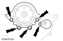
NOTE:Undo the bolts evenly, working in the indicated sequence and undoing each bolt two turns at a time. Detach the camshaft bearing caps. - Remove the valve tappets and lay them in order to one side.
| | | -
CAUTION:Mark the bolts for re-use with one or two punch marks. The bolts can be re-used twice. Discard bolts as required. CAUTION:The cylinder must cool down to ambient temperature before proceeding. Undo the cylinder head bolts. | | | -
Lift off the cylinder head. - Hook the workshop hoist into the engine lifting eyes, lift the cylinder head and place it on clean wooden blocks.
| | | -
Detach the clutch pressure plate and the clutch disk. | | | -
Detach the flywheel/driveplate. | | | -
Remove the drain plug and the oil pan bolts. | | | -
CAUTION:The oil pan must be detached using the specified special tool to avoid damaging the mating face. Do not use a chisel or screwdriver to detach it. Detach the oil pan. - Attach the special tool, tighten the lock nut against the oil pan and use light taps to separate the oil pan from the lower crankcase.
| | | -
Detach the oil intake pipe and the lower crankcase. - Oil intake pipe bolts.
- Remove the lower crankcase bolts.
| | | -
Detach the rear crankshaft oil seal carrier and the crankshaft position sensor (CKP) with its bracket. - CKP sensor bolt
- Four oil seal carrier bolts
| | | -
NOTE:Lay all parts in order to one side. Remove the crankshaft and the pistons. - Remove the big-end bearing caps.
- Remove the main bearing caps.
- Take out the crankshaft and press out the pistons and connecting rods.
| | |