| Disassembly Special Tool(s) | | Remover/Installer, Lower Arm Bushing 204-168 (14-043) | | | Slide Hammer 205-047 (15-011) | | | Mounting Stand 303-435 (21-187) | | | Mounting Bracket for 303-435 303-435-06 (21-031B) | | | Mounting Plate for 303-435-06 303-435-13A (21-170A) | | | Remover, Torque Converter Seal 307-272 (17-061) | General Equipment Disassembly All vehicles | | -
CAUTION:In the case of abraded particles of metal, install a new valve body, fluid pipes, fluid cooler and torque converter. NOTE:Clean the transaxle assembly to prevent the entry of dirt when reassembling. NOTE:Do not clean brake band and friction plates with cleaning agents. NOTE:If, during repair work, abraded particles are found in the transmission fluid (particles from the clutch or metal chips or debris), the transaxle must be disassembled completely and cleaned. Also, clean fluid pipes, fluid cooler and torque converter carefully; in case of extreme soiling the fluid pipes, fluid cooler and torque converter should be newly installed. NOTE:In case of clutch abrasion, rinse the torque converter with clean automatic transmission fluid. NOTE:Before taking measurements, compress all the clutches where axial play is detected to squeeze the oil out from between the plates. Inspect the transaxle components during disassembly. | | | -
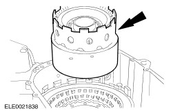
CAUTION:Do not tilt the torque converter when removing it to avoid damaging the torque converter hub. NOTE:The torque converter is filled with fluid. Position it on a table so that fluid will drain out of the torque converter into a drain pan. Remove the torque converter. | Vehicles built up to 03/2003 | | -
CAUTION:Prevent the fluid pipe adapter from turning using an open-ended wrench, do not remove it from the transaxle housing. NOTE:Cap the fluid cooler openings to prevent oil loss or dirt ingress. Remove the fluid cooler pipe from the transaxle. - Detach the fluid pipe bracket from the transaxle.
| | | -
CAUTION:Prevent the fluid pipe adapter from turning using an open-ended wrench, do not remove it from the transaxle housing. NOTE:Cap the fluid cooler openings to prevent oil loss or dirt ingress. Remove the fluid cooler pipe from the transaxle. | All vehicles | | -
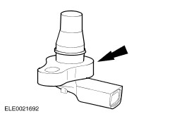
Remove the output shaft speed (OSS) sensor. - Remove and discard the OSS sensor O-ring seal.
| | | -
Using the special tool, secure the transaxle. | | | -
Position the drain pan under the transaxle, remove the drain plug, and drain the transmission fluid. | | | -
Remove the pump assembly driveshaft. | | | -
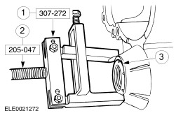
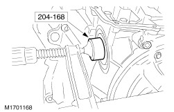
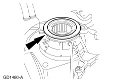
Using the special tools, remove and discard the torque converter impeller hub seal. | | | -
Using the special tools, remove the left-hand and right-hand differential seals. - Install the special tools.
- Remove and discard the differential seals.
| | | -
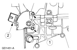
Remove the turbine shaft speed (TSS) sensor. - Remove the bolt.
- Remove the TSS sensor.
| | | -
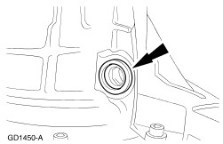
Remove and discard the TSS sensor O-ring seal. | | | -
Remove the transaxle fluid filler tube bolt. | | | -
Remove the transaxle fluid filler tube. | | | -
Remove and discard the transaxle filler tube grommet. | | | -
Remove the transmission range (TR) sensor. - Remove the bolts.
- Remove the TR sensor from the manual valve detent lever shaft.
| | | -
NOTE:Remove the bolts in the sequence shown. Remove the fluid pan cover. - Disconnect the fluid pan vent tube.
| | | -
Remove the fluid pan cover gasket. | | | -
Inspect the fitting of the main control cover vent tube for blockage (if available). | | | -
CAUTION:Only remove the indicated bolts. Remove the main control valve body bolts. | | | -
CAUTION:Do not allow the loose manual valve to become damaged. Disconnect the manual valve link from the manual valve when lifting the main control valve body from the case. | | | -
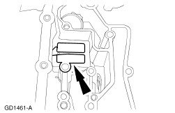
CAUTION:Do not pull the solenoid body electrical connector wires, or use a hammer on the electrical connector. Remove the solenoid body electrical connector. - Release the retaining tabs and push the connector through the transaxle case.
| | | -
Support the manual valve and remove the main control. - Store the main control in a clean, dry location.
| | | -
Remove the thermostatic fluid level control valve bracket. | | | -
Remove the thermostatic fluid level control valve. | | | -
WARNING:The servo is under pressure. WARNING:Servo and servo cover are under high spring force. Use caution when removing the servo cover. Failure to follow these instructions will result in personal injury. NOTE:To aid in the removal of the servo cover, install a nut with an integral washer N621943-S2 (using permanent thread sealer) onto the forcing bolt of the servo cover. Using the special tool, compress the servo cover and remove the snap ring. | | | -
Remove the servo piston assembly. | | | -
Inspect the intermediate and overdrive servo assembly and bore for damage or wear. - Inspect the servo cover and bonded seal.
- Inspect the cushion spring and servo apply rod.
- Inspect the servo return spring.
- Inspect the case servo bore.
| | | -
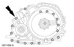
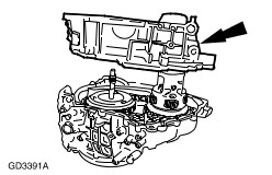
NOTE:Position the transaxle with the torque converter housing facing upward. Remove the 20 bolts. | | | -
NOTE:Place the torque converter housing on the engine flange side after removal to prevent damage to the lube tube. Separate the torque converter housing from the transaxle case. - Remove and discard the transaxle split flange gasket.
| | | -
Remove the final drive carrier and differential assembly. - Remove the differential bearing.
- Remove the differential bearing shim.
- Remove the final drive carrier and differential assembly.
| | | -
Unsnap and remove the chain pan cover. | | | -
Remove the driven sprocket thrust bearing. | | | -
NOTE:The driven sprocket thrust washer may adhere to the converter housing. Remove the driven sprocket thrust washer from the reverse/overdrive ring gear assembly. | | | -
WARNING:Wear gloves as protection from sharp chain and sprocket teeth. Failure to follow these instructions will result in personal injury. Remove the chain drive, reverse/overdrive ring gear, and driven sprocket assembly. | | | -
Separate the drive chain assembly from the driven sprocket assembly and reverse/overdrive ring gear assembly. | | | -
NOTE:Inspect the magnet located on the chain pan for excessive metal particles. Remove the chain pan (with the magnet attached) from the transaxle case. | | | -
Remove the filter recirculation exhaust pipe using an internal puller. - Discard the exhaust pipe.
| | | -
Remove the fluid filter and seal assembly. - Discard the fluid filter.
- Discard the fluid filter seal.
| | | -
Remove the driven sprocket bearing. | | | -
Remove the driven sprocket shim (selective fit). | | | -
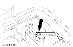
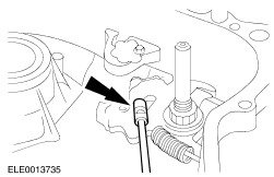
Disconnect the parking lever actuating rod from the parking cam actuator lever assembly. | | | -
Disconnect the parking lever actuation rod from the manual valve detent lever, and remove the parking lever actuation rod. | | | -
NOTE:The thrust bearing may adhere to the reverse/overdrive sprocket. Remove the reverse/overdrive ring gear thrust bearing. | | | -
NOTE:The thrust bearing is part of the reverse/overdrive carrier assembly. Remove the reverse/overdrive carrier assembly with captured thrust bearing. | | | -
Remove the reverse/overdrive sun gear and shell assembly. | | | -
NOTE:The thrust bearing may adhere to the reverse/overdrive sun gear and shell. Remove the reverse/overdrive sun gear and shell thrust bearing. | | | -
Remove the low-intermediate ring gear assembly. | | | -
NOTE:The low-intermediate carrier thrust bearing may adhere to the low-intermediate ring gear. Remove the low-intermediate carrier thrust bearing. | | | -
Remove the low-intermediate carrier assembly. | | | -
Remove the low-intermediate sun gear thrust bearing. | | | -
Remove the forward one-way clutch and low/intermediate sun gear. | | | -
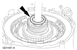
NOTE:The turbine shaft thrust bearing may adhere to the forward one-way clutch and low/intermediate sun gear. Remove the turbine shaft thrust bearing. | | | -
Remove the turbine shaft assembly. | | | -
Remove the forward/coast/direct clutch cylinder assembly and reverse clutch drum assembly from the transaxle. | | | -
NOTE:The pump support thrust bearing assembly may adhere to the reverse clutch drum assembly. Remove the pump support thrust bearing. | | | -
Remove the low one-way clutch retaining ring. | | | -
Remove the low one-way clutch thrust plate. | | | -
Remove the thin, eight wave low/reverse clutch wave spring. | | | -
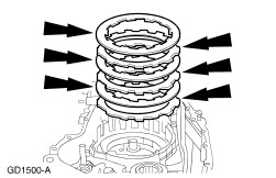
Remove the low/reverse clutch plates. - Inspect the friction plates for partially stripped, stripped, broken or bent spline teeth, burnt, worn or flaked off friction material, and warped or bent friction discs.
- Inspect the steel plates for heat discoloration or distortion.
| | | -
Remove the thick, ten-wave low/reverse clutch wave spring. | | | -
Remove the low/reverse clutch return spring retaining ring. | | | -
Remove the low/reverse clutch return spring assembly. | | | -
NOTE:Rotate the low/reverse clutch piston while pulling upward. Remove the low/reverse clutch piston. | | | -
NOTE:Position the transaxle that the pump assembly is facing upward. Remove the pump assembly bolts. | | | -
Remove the pump assembly. - Using a hammer handle, remove the pump assembly.
| | | -
Remove the intermediate and overdrive band assembly from the case. - Inspect the intermediate and overdrive band assembly for damage and wear.
| |