1
-
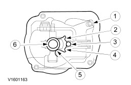
Transmission housing - clutch side
The MTX-75 manual transmission is a "2-shaft transmission".
MTX-75 means:
- M: Manual
- T: Transmission
- X Transaxle (front wheel drive)
- 75 Distance between input and output shaft in mm.
The aluminium transmission housing consists of two closed halves. In order to prevent noise and vibration, the reinforcement ribs on the transmission housing have been modified. Because of this, the pre-load on the shafts and the differential bearings has been increased.
To improve the lubrication of the 3rd gear wheel, an additional drip plate has been fitted to the selector fork, allowing more oil to drip onto the 3rd gear synchronizer rings.
With the "2-shaft transmission" all the gear wheels are in permanent mesh. The relevant ratio is achieved using one pair of gearwheels per gear.
When reverse gear is selected, the direction of rotation of the output shaft is changed by an idler gear.
The input and output shafts run in taper roller bearings.
To further improve stability and gearshifting, the selector mechanism has been revised to incorporate a maintenance-free cable operating mechanism.
All the gear wheels, including reverse gear, are bevel-cut, synchronised and run on needle roller bearings.
First, second and third gear are double-synchronised, thus enabling smooth gear changes.
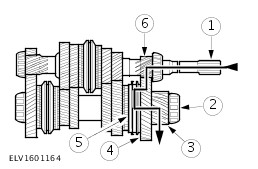
Input and Output Shaft
General View of Input and Output Shaft
5
-
3rd/4th gear synchronizer
13
-
1st/2nd gear synchronizer
18
-
5th/reverse gear synchronizer
In neutral, none of the gears is connected to the input or output shaft via the relevant synchronizer unit. No torque is transmitted to the differential.
The input and output shafts are each seated in one taper roller bearing in the transmission housing section on the clutch side and one taper roller bearing in the transmission housing section on the transmission side.
The output shaft drive pinion is in constant engagement with the differential drive annulus.
The 3rd and 4th gear wheels and the 3rd/4th gear synchronizer are located on the input shaft The 1st, 2nd and reverse gear teeth are part of the input shaft.
The 1st, 2nd, 5th and reverse gear wheels and the 1st/2nd gear synchronizer and the 5th/reverse gear synchronizer are located on the output shaft. The gear teeth for the 3rd and 4th gears are part of the output shaft (vehicles built up to 07.2000).
Differential
The main components of the differential are:
- Output gear wheel
- Spur gear
- Four pinions at right angles to one another
- Differential housing with two taper roller bearings
The transmission and differential are installed in a two-part aluminium housing which is flange-mounted to the engine.
The driveshafts have serrated teeth and are secured with a snap-ring.
The torque is transmitted from the spur gear to the driveshafts via two differential pinions mounted on the differential pinion shaft and the driveshaft pinions.
When cornering, the drive gears need to turn at different speeds as the road wheels travel different distances. This is achieved by means of the differential pinions which turn on their own shaft and mesh with the driveshaft pinions turning at different rates.
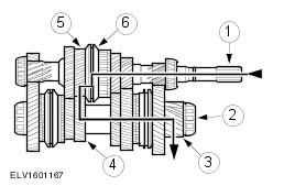
Power Flow
1st gear