| Installation Special Tool(s) | | Spanner, for steering gear 211-186 (13013) | | | Subframe locating pins 205-316 (15097A) | | | Engine support bar 303-290 (21140) | | | Adapter for 303-290 303-290-01 (2114001) | | | Adapter for 303-290 303-290-02 (2114002) | | | Adapter for 303-290 303-290-03 (2114003) | | | Adjuster, for shift lever 308-273 (16088A) | | | Alignment gauge, for powertrain 502-003 (21172) | General Equipment Transmission jack Retaining strap Materials Name Specification Cable ties High-temperature grease ESD-M2G269-A Brake fluid ESD-M6C57-A Installation All Vehicles | | -
Prepare the transmission for installation. | | | -
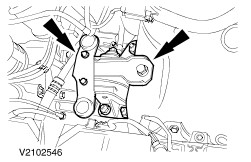
Move the transmission into position using the transmission jack. Screw in the flange bolts on the right-hand transmission side and attach the catalytic converter bracket. | | | -
Screw in the flange bolts and fit the starter motor. - Screw in the flange bolts.
- Tighten the starter motor nuts.
- Attach the starter motor bracket.
| | | -
Fit the bracket for the left-hand engine roll restrictor. | | | -
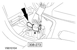
NOTE:The adjusting mechanism must be unlocked. Attach the gearshift cables to the transmission and adjust them. NOTE:The abutment brackets are tensioned automatically once they are released. - Slacken the abutment bracket by turning it anti-clockwise and fit the cable in the bracket.
- Connect the selector cable to the gear selector lever.
- Slacken the abutment bracket by turning it anti-clockwise and fit the cable in the bracket.
- Connect the shift cable to the gearshift lever.
- Lock the adjusting mechanism by pressing in the tab.
| | | -
Raise the engine with transmission to installation height. | | | -
CAUTION:Screw in the nuts until they make contact, then slacken them one turn. Attach the rear engine support bracket to the transmission. | | | -
CAUTION:Screw in the nuts until they make contact, then slacken them one turn. Attach the front engine mounting bracket. | | | -
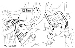
Connect the plug and attach the wiring harness to the transmission. - Connect the plug to the reversing light switch.
- Connect the plug for the vehicle speed sensor (VSS) and clip it into the bracket.
- Route the wiring and attach the wiring harness bracket to the transmission.
| | | -
CAUTION:The inner joint must not be bent more than 18 degrees, the outer one no more than 45 degrees. NOTE:Make sure the snap-ring locates correctly. Fit the left-hand front driveshaft. - Fit the front driveshaft with its new snap-ring into the transmission.
| | | -
CAUTION:The inner joint must not be bent more than 18 degrees, the outer one no more than 45 degrees. NOTE:Lower nut with refrigerant pipe bracket. Install the right-hand front axle driveshaft. - Fit the front axle driveshaft in the transmission, centre bearing bracket and wheel hub.
| | | -
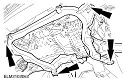
NOTE:Screw in the nuts until they make contact, then slacken them one turn. Fit the subframe. - Detach the front engine roll restrictor from the subframe.
| | | -
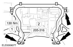
Align the subframe. - Insert the special tools.
- Align the subframe so that the special tools are centred in the body centring holes on the left and right (left-hand side shown).
| | | -
NOTE:The subframe must not move during the tightening operation. Secure the subframe. - Tighten the bolts working diagonally.
- Remove the special tools.
| | | -
Align the engine/transmission assembly. - Fit the special tool in the place of the left-hand engine roll restrictor.
- Screw in the bolts.
- Fit the centre bolt and tighten by hand.
| | | -
CAUTION:Do not distort or turn the engine mounting. Tighten the rear engine mounting bracket nuts. - Tighten the air filter bracket.
| | | -
CAUTION:Do not distort or turn the engine mounting. Tighten the front engine mounting bracket nuts. | | | -
Remove the special tools. | | | -
Attach the bracket of the right-hand engine roll restrictor to the transmission. | | | -
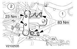
CAUTION:Do not tilt the engine roll restrictor. Attach the right-hand engine roll restrictor. - Tighten the bolts.
- Tighten the centre screw.
| | | -
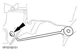
CAUTION:Do not tilt the engine roll restrictor. Attach the left-hand engine roll restrictor. - Move the engine roll restrictor into position.
- Tighten two bolts.
- Tighten the centre screw.
| | | -
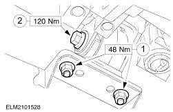
Attach the steering gear to the subframe. | | | -
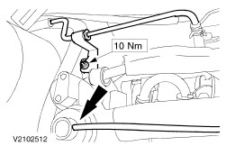
CAUTION:Do not damage the boots and the ABS sensor ring. Attach the stabiliser link rod and the suspension lower arm ball joint on both sides. | | | -
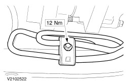
Attach the right-hand and left-hand bumper bar brace to the subframe (right-hand side shown). | | | -
Attach the power steering pipe to the subframe. | | | -
Attach the power steering pipe to the subframe (continued). | Vehicles with air conditioning | | -
Attach the air conditioning dryer to the subframe. | All vehicles | | -
Fit the left and right-hand lower wheel arch trim panels (right-hand side shown). | | | -
Attach the lower radiator cover. | | | -
Attach the engine undershield (if fitted). | | | -
Connect together two engine main wiring harness connectors. - Route the engine main wiring harness and secure with cable ties .
| | | -
CAUTION:Brake fluid may leak out. Observe the safety procedures for handling brake fluid. Connect the high-pressure pipe to the clutch slave cylinder. - Fit the high-pressure pipe in the bracket.
- Fit the spring clip in the slave cylinder pipe.
| | | -
NOTE:One bolt with ground lead. Screw in the upper flange bolts. | | | -
Attach the catalytic converter to the exhaust manifold. | | | -
Attach the power steering pipe to the bracket and push on the EGR valve hose. | | | -
Fit the air cleaner. - Clip on the air cleaner intake.
- Push on the vacuum hose.
- Tighten the hose clip.
- Connect the MAF connector.
| | | -
Tighten the wheel nuts for both wheels. | | | -
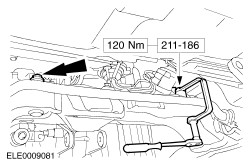
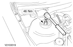
Tighten the left-hand suspension nut strut (right-hand side shown). - Counterhold using an Allen key.
- Tighten until finger-tight using a ring spanner.
- Tighten to specified torque using a torque wrench.
| | | -
Remove the special tool from the selector gate and fit the boot and bellows. | | | -
Standard finishing operations. - Connect the battery ground cable.
- Reprogram the preset radio stations.
- Carry out a road test to enable the PCM to collect data.
- Check the routing of the vacuum hoses and wiring and secure them with cable ties .
- Check fluid levels and correct if necessary.
| |