| Assembly Special Tool(s) | | Bearing outer race installer 205-075 (15036) | | | Installer, bearing outer race and oil seal 204-050 (14024) | | | Installer, bearing outer race and oil seal 204-017 (14010) | | | Valve spring compressor 306-060 (21024) | | | Adapter for 306-060 306-060-02 (2102402) | | | Adapter for 306-060 306-060-07 (2102407) | | | Measuring fixture, input shaft end float 308-194 (16059A) | | | Socket wrench 205-175 (15073) | | | Torque gauge 205-067 (15041) | | | Installer, differential oil seal 205-115 (15058) | | | Installer, input shaft oil seal 307-210 (17041) | General Equipment Press Hot air blower Dial indicator Magnetic stand for dial indicator Attach a steel plate (e.g. 303-435-11 (21146C)) Materials Name Specification Transmission fluid WSD-M2C200-C Sealer, transmission housing WSK-M2G348-A5 Sealer, slave cylinder ESKM-4G269-A Temperature reduction spray Assembly All vehicles | | -
Clean and check all parts carefully before reassembly. | | | -
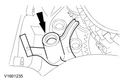
Install the reverse gear idler shaft. - Coat the mating face of the reverse gear idler shaft with sealer .
- Position the reverse gear idler shaft with the locating bolt and drive it in.
- Unscrew the guide bolt and install the original bolts.
| | | -
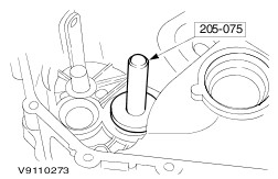
CAUTION:The press pressure must not exceed 15 kN. Install the bearing cups on the transmission housing side. - Heat up the transmission to approximately 80C using a hot air blower .
- Using the press , fit the bearing cups of the:
- input shaft using Special Tool 307-210 (17-041)
- output shaft using 205-075 (15-036)
- differential using Special Tool 204-050 (14-024)
| | | -
Measuring shim to be fitted: | | | -
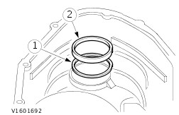
CAUTION:The press pressure must not exceed 15 kN. Install the measuring shims and the bearing cups in the housing section at the clutch end. - Heat up the transmission locally to approximately 80°C using a hot air blower .
- Install the measuring shims.
- Install the bearing cups.
- Install the bearing cups of the:
- input shaft using Special Tool 204-017 (14-010)
- output shaft using 205-075 (15-036)
- differential using Special Tool 204-050 (14-024)
| | | -
NOTE:Do not oil taper roller bearings which are to be used again. New taper roller bearings can be fitted without any treatment. Install the input shaft and the output shaft in the transmission housing. - Assemble the input shaft and the output shaft together and fit them in the transmission housing.
| | | -
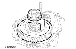
NOTE:Do not oil taper roller bearings which are to be used again. New taper roller bearings can be fitted without any treatment. Install the differential assembly. | | | -
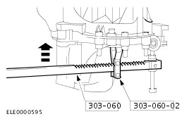
NOTE:Check that the mating face is clean. Install the housing (clutch end). - Attach the special tool to the transmission housing flange using the longer bolt.
| | | -
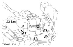
Secure the housing (clutch end). - Tighten the 16 flange bolts uniformly.
| | | -
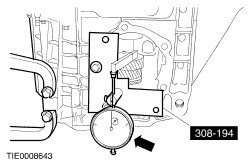
Attach the special tool. - Position the measuring bar on the 4th gear wheel.
| | | -
Prepare the input shaft for measuring. - Turn the input shaft to and fro approximately 20 times to settle the bearings.
| | | -
NOTE:Carry out the preparations and the measurement 3 times and calculate the average value of the measurements. Measure the input shaft end float. - Lift the input shaft with a lever.
- Note the resulting measurement (e.g. 0,22 mm).
- Example: 0,22 mm + 0,23 mm + 0,21 mm divided by three = 0,22 mm.
| | | -
Prepare the output shaft for measuring. - Turn the output shaft back and forth 20 times to settle the bearings (via input shaft, refer to step 12).
| | | -
NOTE:Carry out steps (15) and (16) three times and calculate the average measurement. Measure the output shaft end float. - Lift the output shaft with a lever and note the resulting measurement, e.g. 0,32 mm.
- Example: 0,32 m + 0,34 mm + 0,33 mm divided by three = 0,33 mm.
| | | -
Prepare the differential for measuring. - Turn the output shaft backwards and forwards 20 times and at the same time press down the differential.
| | | -
NOTE:Carry out steps 17 and 18 three times and calculate the average measurement. Measure the differential end float. - Lift the differential with the special tool and note the resulting measurement, e.g. 0,34 mm.
- Example: 0,34 mm + 0,36 mm + 0,38 mm divided by three = 0,36 mm
| | | -
Calculate the required input shaft shim thickness. - Required shim thickness 1,00 mm.
- Measured input shaft end float 0,22 mm.
- Preload figure for end float -0,05 mm.
- Required shim: 0,22 mm - 0,05 mm + 1,00 mm = 1,17 mm.
| | | -
Calculate the required output shaft shim thickness. - Calculated output shaft end float 0,33 mm.
- Required shim: 1,00 mm + 0,33 mm + 0,13 mm = 1,46 mm.
| | | -
Calculate the required differential shim thickness. - Required shim thickness 1,10 mm.
- Calculated differential end float 0,36 mm.
- Required shim: 1,10 mm + 0,36 mm + 0,33 mm = 1,79 mm.
| | | -
Remove the bearing cups again. - Remove the bearing cups of the:
| | | -
Install the shims and bearing cups. - Install the required shims.
- Install the bearing cups of the:
| | | -
Installation hook for reverse gear idler (to be fabricated by technician). - Diameter of the wire: 3 mm.
| | | -
Reverse gear idler (installation sequence). - Lower thrust washer
- Needle roller bearing
- Reverse gear idler
- Upper thrust washer
- Reverse gear idler shaft mounting
| | | -
NOTE:Insert the reverse gear idler with the small collar facing downwards. Insert the assembly hook and install the reverse gear idler together with the mounting. | | | -
NOTE:Lubricate the taper roller bearing. Install the input and output shafts. - Insert the input and output shafts together and swivel them to one side.
- Remove the installation hook.
| | | -
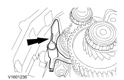
NOTE:Make sure the 4th gear selector ring is in the neutral position. Install the selector fork. - Install the 5th/reverse gear selector fork and swivel it to the side.
| | | -
Install the 3rd/4th gear selector fork. - Swing the 5th/reverse gear selector fork back.
| | | -
NOTE:If the holes for the reverse gear idler shaft mounting bolts do not line up exactly, check the installation position of the reverse gear idler shaft thrust washers. Install the bolts for the reverse gear idler shaft mounting. - Press the mounting down as far as it will go.
- Coat the bolts with sealer and tighten them.
| | | -
NOTE:When fitted correctly, the selector rods are the same height. Install the 1st/2nd gear selector fork and selector rods. | | | -
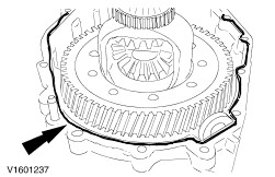
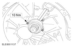
Install the differential assembly. - Install the differential assembly.
- Place the clean magnetic disk in the recess.
| | | -
- The mating face must be dry of oil. Evenly apply transmission housing sealer to the inside of the mating face (even 2 mm bead of sealer).
| | | -
NOTE:The transmission housing must not be turned over to tighten the bolts. Install the housing (clutch end). - Tighten the 16 flange bolts within 15 minutes, working diagonally.
| Vehicles built up to 10.1999 inclusive | | -
NOTE:Make sure the transmission is in neutral (the gearshift lever and selector lever must be vertical). Install the selector mechanism. - The mating face must be oil dry. Evenly apply transmission housing sealer to the outside of the mating face (even 2 mm bead of sealer).
- M8 x 35 mm bolts.
- M8 x 85 mm bolts.
| Vehicles built from 11.1999 | | -
NOTE:Make sure the selector mechanism is in neutral. Install the selector mechanism. | | | -
Install the shift mechanism cover. | All vehicles | | -
Measure the turning torque. - Measure the turning torque.
- If the turning torque is too high, all the measurements (to establish the required shim thickness) must be repeated.
| Vehicles with diesel engine | | -
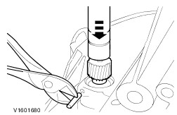
Install the speedometer drive pinion. - Carefully drive in the roll pin.
| Vehicles with 1.6, 1.8 or 2.0 engine | | -
Install the vehicle speed sensor (VSS). | All vehicles | | -
Install the front driveshaft oil seals. | | | -
NOTE:Install a new clutch slave cylinder. | |