| Installation Special Tool(s) | | Engine support bar 303-290 (21140) | | | Adapter for 303-290 303-290-01 (2114001) | | | Adapter for 303-290 303-290-02 (2114002) | | | Adapter for 303-290 303-290-03 (2114003) | | | Spanner, for steering gear 211-186 (13013) | | | Alignment gauge, for powertrain 502-003 (21172) | | | Subframe locating pins 205-316 (15097A) | | | Adjuster, Shift lever 308-273 (16088A) | | | Spanner, intake manifold 303-210 (21066) | General Equipment Transmission jack Auxiliary plugs Retaining strap Materials Name Specification Cable ties Brake fluid ESD-M6C57-A Transmission fluid WSD-M2C200-C Installation All Vehicles | | -
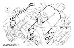
Install the attachments on the transmission. - Starter
- Vehicle speed sensor (VSS)
| | | -
Move the transmission into position using the transmission jack. | | | -
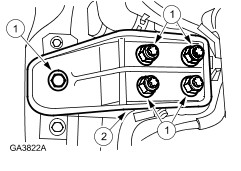
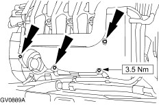
Screw in the three bottom front flanged bolts. | | | -
Screw in the three bottom rear flanged bolts. | | | -
Remove the retaining strap from the transmission and take away the transmission jack. | | | -
NOTE:The transmission is in "neutral" when the selector and shift lever are vertical. Move the selector and shift lever into "neutral". | | | -
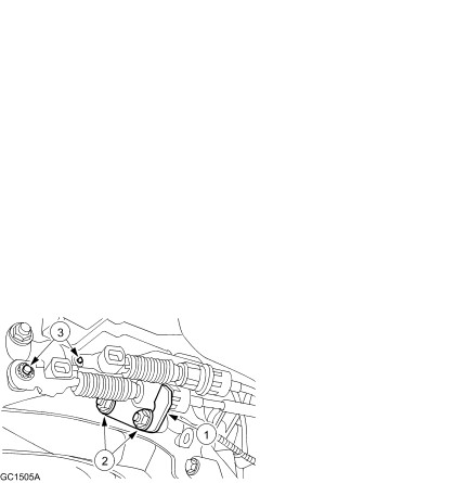
Install the gearshift and selector cable. - Install the bracket.
- Screw on the nuts.
- Install the gearshift and selector cable.
| | | -
Adjust the gearshift and selector cable. | | | -
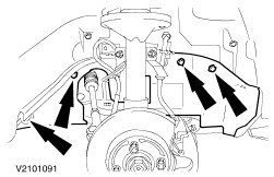
Install the steering gear (two bolts, left-hand side shown). | | | -
Install the steering gear heat shield and the oil line bracket. | | | -
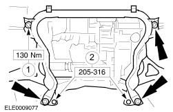
NOTE:Screw in the bolts until they make contact, then slacken them one turn. Install the subframe. | | | -
Install the right-hand engine roll restrictor bracket. | | | -
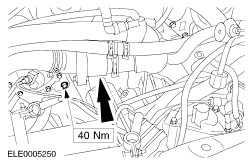
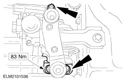
Install the right-hand engine roll restrictor. - Tighten the bolts.
- Tighten the centre screw.
| | | -
Align the subframe. - Align the subframe so that the special tool is centred in the vehicle body alignment holes on the left and right (left-hand side shown).
| | | -
CAUTION:The subframe must not move during the tightening operation. Secure the subframe. - Tighten the bolts working diagonally.
- Take off the special tool.
| | | -
Install the bracket for the left-hand engine roll restrictor. | | | -
Align the engine with the transmission. - Install the special tool on the subframe and in the left-hand engine roll restrictor bracket.
- Screw the central bolt into the special tool and tighten it.
| Vehicles with air conditioning | | -
Attach the air conditioning dryer to the subframe. | All vehicles | | -
Install the left-hand and right-hand braces on the subframe. | | | -
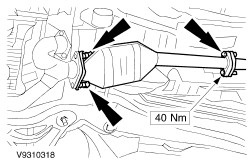
Install the rear catalytic converter with a new gasket and attach it. | | | -
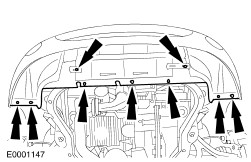
Install the lower radiator cover. | | | -
CAUTION:The inner joint must not be bent more than 18 degrees, the outer one no more than 45 degrees. NOTE:Make sure the new snap ring clips firmly into place. Install the left-hand driveshaft. | | | -
CAUTION:The inner joint must not be bent more than 18 degrees, the outer one no more than 45 degrees. NOTE:Do not damage the new sealing ring. Install the right-hand driveshaft/intermediate shaft. - Install the intermediate shaft centre bearing.
| | | -
Install the oil line bracket on the subframe. | | | -
CAUTION:Do not damage the boots and the ABS sensor ring. Install both the lower suspension arms and stabiliser connecting links (right-hand side shown without front wheel). | | | -
Install the lower wheel arch trim panel (shown without front wheel). | | | -
NOTE:Top up with transmission fluid until fluid is 0-5 mm below the filler hole. | | | -
Connect the starter motor. | | | -
CAUTION:Brake fluid will escape. Observe the safety precautions when dealing with brake fluid. Install the clutch slave cylinder. | | | -
Join VSS connector and reversing light. | | | -
Tighten top flanged bolts (two bolts). | | | -
NOTE:Do not tighten nuts and bolts. Use new self-locking nuts. Install the left-hand transmission bracket. | | | -
Slacken the right-hand engine bracket and take off the high-tension lead bracket. - Undo the nuts.
- Undo the bolt.
| | | -
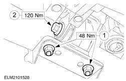
Tighten the left-hand transmission bracket. | | | -
Install the right-hand engine bracket. - Tighten the nuts and the bolt.
- Install the high-tension lead bracket.
| | | -
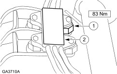
NOTE:The engine roll restrictor must be installed so that it is fully centred in the engine roll restrictor bracket. Otherwise, realign the powertrain assembly with the subframe. For additional information, refer to Section 303-01A Engine / 303-01B Engine / 303-01C Engine / 303-01D Engine. Install the left-hand engine roll restrictor. - Tighten the nuts.
- Tighten the central bolt of the engine roll restrictor.
| | | -
NOTE:The engine roll restrictor must be installed so that it is fully centred in the engine roll restrictor bracket. Otherwise, realign the powertrain assembly with the subframe. For additional information, refer to Section 303-01A Engine / 303-01B Engine / 303-01C Engine / 303-01D Engine. Tighten the central bolt of the right-hand engine roll restrictor. | | | -
Install the cables. - Cruise control cable (if fitted)
- Accelerator cable
| | | -
Install the coolant pump cover. - Clip in the coolant hose.
| | | -
Pull out the pins from both sides of the radiator (left-hand side shown). | | | -
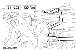
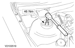
Tighten the suspension strut nut on both sides. - Counterhold using an Allen key.
- Tighten until finger-tight using a ring spanner.
- Tighten to specified torque using a torque wrench.
| | | -
Standard finishing operations. - Remove special tool 308-273.
- Check fluid levels and correct if necessary.
- Check the routing of the vacuum hoses and cables and fix them using cable ties if necessary.
- Reprogram the preset radio stations.
- Carry out a road test to enable the PCM to collect data.
- Check fluid levels again and correct if necessary.
| |