| PINPOINT TEST E : A SINGLE ILLUMINATION SOURCE IS INOPERATIVE |
| TEST CONDITIONS | DETAILS/RESULTS/ACTIONS |
| E1: CHECK ILLUMINATION SOURCE |
| | 1 Ignition switch in position 0. |
| | 2 CHECK the inoperative bulb. |
| | Is the bulb okay? Yes REINSTALL the bulb, if the inoperative bulb is in the instrument cluster, INSTALL a new instrument cluster. REFER to Section 413-01 Instrument Cluster. TEST the system for normal operation. If the inopertative bulb is in the audio unit. GO to D1. GO to Pinpoint Test D. . If the inoperative bulb is in the heater panel, INSTALL a new heater panel illumination. REFER to Section 412-04 Control Components. If the inoperative bulb is in the gearshift lever, GO to E2. GO to Pinpoint Test E. . If the inoperative bulb is in the cigar lighter, GO to E4. GO to Pinpoint Test E. . If the inoperative bulb is in the rear window heater switch, GO to E6. GO to Pinpoint Test E. . If the inoperative bulb is in the headlamp switch panel, GO to E7. GO to Pinpoint Test E. . If the inoperative bulb is in the power window switch, GO to E9. GO to Pinpoint Test E. . If the inoperative bulb is in the traction control switch, GO to E11. GO to Pinpoint Test E. . If the inoperative bulb is in the liquefied petroleum gas (LPG) tank gauge, GO to E12. GO to Pinpoint Test E. . No INSTALL a new bulb. TEST the system for normal operation. |
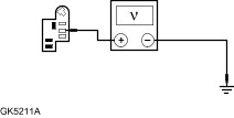
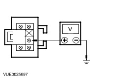
| E2: CHECK CIRCUIT 64S-LK21 (BU/BK) FOR VOLTAGE |
| | 1 Disconnect Gearshift Lever C931. |
| | 2 Place the headlamp switch in the ON position. |
| | 3 Measure the voltage between gearshift lever C931 pin 5, circuit 64S-LK21 (BU/BK), harness side and ground. |
| | Is the voltage greater than 10 volts? Yes No REPAIR the circuit. TEST the system for normal operation. |
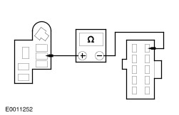
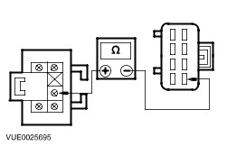
| E3: CHECK CIRCUIT 31-LK21 (BK) FOR OPEN |
| | 1 Measure the resistance between gearshift lever C931 pin 6, circuit 31-LK21 (BK), harness side and ground. |
| | Is the resistance less than 5 ohms? Yes INSTALL a new gearshift illumination bulb. TEST the system for normal operation. No REPAIR the circuit. TEST the system for normal operation. |
| E4: CHECK CIRCUIT 64S-LK15 (BU/BK) FOR VOLTAGE |
| | 1 Disconnect Cigar Lighter C912b. |
| | 2 Measure the voltage between cigar lighter C912b pin 2, circuit 64S-LK15 (BU/WH), harness side and ground. |
| | Is the voltage greater than 10 volts? Yes No REPAIR the circuit. TEST the system for normal operation. |
| E5: CHECK CIRCUIT 31-HA6 (BK) FOR OPEN |
| | 1 Measure the resistance between cigar lighter C912b pin 1, circuit 31-HA6 (BK), harness side and ground. |
| | Is the resistance less than 5 ohms? Yes INSTALL a new cigar lighter bulb. TEST the system for normal operation. No REPAIR the circuit. TEST the system for normal operation. |
| E6: CHECK CIRCUIT 31-LH37 (BK) FOR OPEN |
| | 1 Disconnect Rear Windshield Heater Switch C437. |
| | 2 Measure the resistance between rear windshield heater switch C437 pin 4, circuit 31-LH37 (BK), harness side and ground. |
| | Is the resistance less than 5 ohms? Yes INSTALL a new rear windshield heater switch. TEST the system for normal operation. No REPAIR the circuit. TEST the system for normal operation. |
| E7: CHECK CIRCUIT 29S-LH26 (OG/BK) FOR VOLTAGE |
| | 1 Disconnect Headlamp Switch Illumination C406. |
| | 2 Measure the voltage between headlamp switch illumination C406 pin 2, circuit 29S-LH26 (OG/BK), harness side and ground. |
| | Is the voltage greater than 10 volts? Yes No REPAIR the circuit. TEST the system for normal operation. |
| E8: CHECK CIRCUIT 31-LH26 (BK) FOR OPEN |
| | 1 Measure the resistance between headlamp illumination switch C406 pin 1, circuit 31-LH26 (BK), harness side and ground. |
| | Is the resistance less than 5 ohms? Yes INSTALL a new illumination bulb socket. TEST the system for normal operation. No REPAIR the circuit. TEST the system for normal operation. |
| E9: CHECK THE VOLTAGE TO THE INOPERATIVE WINDOW SWITCH BULB |
| | 1 Disconnect Inoperative Switch. |
| | 2 Measure the voltage between the inoperative switch and ground, refer to the following: - Driver side C74b pin 2, circuit 15-AJ7A (GN/BU), harness side.
- Passenger side C489 pin 2, circuit 15S-AJ2 (GN/BU), harness side.
- Right-hand side rear C490 pin 2, circuit 15S-AJ2 (GN/BU), harness side.
- Left-hand side rear C1854 pin 2, circuit 15S-AJ2 (GN/BU), harness side.
|
| | Is the voltage greater than 10 volts? Yes No REPAIR the circuit in question. TEST the system for normal operation. |
| E10: CHECK THE GROUND TO THE INOPERATIVE WINDOW SWITCH BULB |
| | 1 Measure the resistance between inoperative switch and ground, refer to the following: - Driver side C74b pin 3, circuit 31-AJ7 (BK), harness side.
- Passenger side C489 pin 4, circuit 31-LH23 (BK), harness side.
- Right-hand side rear C490 pin 4, circuit 31-LA1 (BK), harness side.
- Left-hand side rear C1854 pin 4, circuit 31-LA1 (BK), harness side.
|
| | Is the resistance less than 5 ohms? Yes INSTALL a new switch. TEST the system for normal operation. No REPAIR the circuit is question. TEST the system for normal operation. |
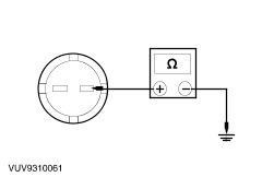
| E11: THE TRACTION CONTROL ILLUMINATION BULB IS INOPERATIVE |
| | 1 Disconnect Traction Control Switch C717. |
| | 2 Measure the resistance between traction control switch C717 pin 7, circuit 31-LH45 (BK), harness side and ground. |
| | Is the resistance greater than 10,000 ohms? Yes REPAIR circuit 31-LH45 (BK). TEST the system for normal operation. No INSTALL a new traction control switch. TEST the system for normal operation |
| E12: THE LIQUEFIED PETROLEUM GAS (LPG) FUEL TANK GAUGE BULB IS INOPERATIVE |
| | 1 Switch the lighting system ON. |
| | Does the cigar lighter illumination operate correctly? Yes No |
| E13: CHECK CIRCUIT 8-LG11A (WH/VT) FOR VOLTAGE |
| | 1 Disconnect LPG Switch C3028. |
| | 2 Measure the voltage between the LPG switch C3028 pin 8, circuit 8-LG11A (WH/VT), harness side and ground. |
| | Is the voltage greater than 10 volts? Yes No |
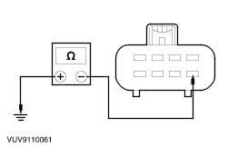
| E14: CHECK THE GROUND CIRCUIT FOR OPEN |
| | 1 Measure the resistance between the LPG switch C3028 pin 4, (BK), harness side and ground. |
| | Is the resistance less than 5 ohms? Yes INSTALL a new LPG switch. TEST the system for normal operation. No REPAIR the circuit (BK). TEST the system for normal operation. |
| E15: CHECK THE CIRCUIT 8-LG11A (WH/VT) FOR OPEN |
| | 1 Disconnect Cigar Lighter C912b. |
| | 2 Measure the resistance between the LPG switch C3028 pin 8, circuit 8-LG11A (WH/VT), harness side and cigar lighter C912b pin 2, circuit 8-LG11A (WH/VT), harness side. |
| | Is the resistance less than 0.5 ohms? Yes No REPAIR the circuit. TEST the system for normal operation. |
| E16: CHECK CIRCUIT 8-LG11 (WH/VT) FOR VOLTAGE |
| | 1 Connect LPG Switch C3028. |
| | 2 Connect Cigar Lighter C912b. |
| | 3 Disconnect LPG Fuel Tank Gauge C3029. |
| | 4 Measure the voltage between the LPG fuel tank gauge C3029 pin 5, circuit 8-LG11 (WH/VT), harness side and ground. |
| | Is the voltage greater than 10 volts? Yes No |
| E17: CHECK THE GROUND CIRCUIT FOR OPEN |
| | 1 Measure the resistance between the LPG fuel tank gauge C3029 pin 6, (BK), harness side and ground. |
| | Is the resistance less than 5 ohms? Yes INSTALL a new LPG fuel tank gauge. TEST the system for normal operation. No REPAIR the circuit. TEST the system for normal operation. |
| E18: CHECK CIRCUIT 8-LG11 (WH/VT) FOR OPEN |
| | 1 Disconnect LPG Switch C3028. |
| | 2 Measure the resistance between the LPG fuel tank gauge C3029 pin 5, circuit 8-LG11 (WH/VT), harness side and the LPG switch C3028 pin 8, circuit 8-LG11 (WH/VT), harness side. |
| | Is the resistance less than 0.5 ohms? Yes No REPAIR the circuit. TEST the system for normal operation. |