| PINPOINT TEST A : THE CHARGING SYSTEM WARNING INDICATOR IS ON WITH THE ENGINE RUNNING |
| TEST CONDITIONS | DETAILS/RESULTS/ACTIONS |
| A1: CHECK THE BATTERY |
| | 1 Carry out the battery capacity test using WDS. |
| | Is the battery OK? Yes If equipped with a zetec or duratec engines. GO to A2. GO to Pinpoint Test A. . If equipped with a diesel engine. GO to A3. GO to Pinpoint Test A. . No INSTALL a new battery. TEST the system for normal operation. |
| A2: CHECK BATTERY JUNCTION BOX (BJB) FUSE 2 |
| | 1 CHECK Battery Junction Box (BJB) fuse 2. |
| | Is the fuse 2 OK? Yes No INSTALL a new fuse. TEST the system for normal operation. If the problem persists check for a short to ground. |
| A3: CHECK THE CHARGING SYSTEM |
| | 1 Carry out the power supply test using WDS. |
| | Is the generator output OK? Yes No |
| A4: CHECK FOR GROUND |
| | 1 Ignition switch in position II. |
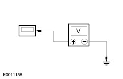
| | 2 Measure the voltage between the generator housing and the battery negative terminal. |
| | Is the voltage less than 0.5 volts? Yes No CLEAN and TIGHTEN the generator mounting, engine to body ground strap, and battery cable. TEST the system for normal operation. If the concern persists, INSTALL a new battery ground cable. |
| A5: CHECK BATTERY CABLE |
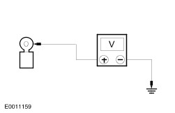
| | 1 Ignition switch in position II. |
| | 2 Measure the voltage between the generator B+ terminal and the battery positive terminal. |
| | Is the voltage less than 0.5 volts? Yes If equipped with a zetec engine. GO to A6. GO to Pinpoint Test A. . If equipped with a duratec engine. GO to A7. GO to Pinpoint Test A. . If equipped with a diesel engine. GO to A8. GO to Pinpoint Test A. . No CLEAN and TIGHTEN the battery positive cable connections. TEST the system for normal operation. If the concern persists, INSTALL a new battery positive cable. |
| A6: CHECK BATTERY FEED TO THE GENERATOR (ZETEC ENGINE) |
| | 1 Ignition switch in position 0. |
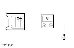
| | 2 Disconnect Generator C2007b. |
| | 3 Measure the voltage between the generator B+ terminal, C2007b pin 1, circuit 30 (RD), harness side and ground. |
| | Is the voltage greater than 10 volts? Yes No REPAIR circuit 30 (RD). TEST the system for normal operation. |
| A7: CHECK BATTERY FEED TO THE GENERATOR (DURATEC ENGINE) |
| | 1 Ignition switch in position 0. |
| | 2 Disconnect Generator C863b. |
| | 3 Measure the voltage between the generator B+ terminal, C863b circuit 30 (RD), harness side and ground. |
| | Is the voltage greater than 10 volts? Yes No REPAIR circuit 30 (RD). TEST the system for normal operation. |
| A8: CHECK BATTERY FEED TO THE GENERATOR (DIESEL ENGINE) |
| | 1 Ignition switch in position 0. |
| | 2 Disconnect Generator C863b. |
| | 3 Measure the voltage between the generator B+ terminal, C863b circuit 30-BA1 (RD), harness side and ground. |
| | Is the voltage greater than 10 volts? Yes No REPAIR circuit 30-BA1 (RD). TEST the system for normal operation. |
| A9: CHECK POWER TO THE VOLTAGE REGULATOR (ZETEC ENGINE) |
| | 1 Disconnect Generator C2007a. |
| | 2 Measure the voltage between the generator C2007a pin 3, circuit 30-BA8 (RD), harness side and ground. |
| | Is the voltage greater than 10 volts? Yes No REPAIR circuit 30-BA8 (RD). TEST the system for normal operation. |
| A10: CHECK POWER TO THE VOLTAGE REGULATOR (DURATEC ENGINE) |
| | 1 Disconnect Generator C863a. |
| | 2 Measure the voltage between the generator C863a pin 3, circuit 30-BA8 (RD), harness side and ground. |
| | Is the voltage greater than 10 volts? Yes No REPAIR circuit 30-BA8 (RD). TEST the system for normal operation. |
| A11: CHECK THE POWERTRAIN CONTROL MODULE (PCM) AND COMMUNICATIONS LINK WITH THE GENERATOR |
| | 1 Connect C2007a or C863a. |
| | 2 Connect the diagnostic tool. |
| | 3 Ignition switch in position II. |
| | 4 Retrieve PCM diagnostic trouble codes (DTCs). |
| | Are any DTCs retrieved? Yes Use WDS to diagnose the PCM and communications. TEST the system for normal operation. No |