ford Workshop Repair Guides

Ford Workshop Service and Repair Manuals

Charging System - Vehicles Built From: 05-1999 > < Charging System
Charging System - General Information - Charging System—Vehicles Built Up To: 05/1999 Mondeo 1997 (08/1996-09/2000)
Diagnosis and Testing

Refer to Wiring Diagrams Section 414-00, for schematic and connector information.

Inspection and Verification

  1. Verify the customer concern.
  1. Visually inspect for obvious signs of mechanical and electrical damage.

Visual Inspection Chart

Mechanical Electrical
  • Accessory drive belt
  • Generator
  • Hardware
  • Fuse(s)
  • Charging system warning indicator bulb
  • Battery
  • Electrical connector(s)
  1. If an obvious cause for an observed or reported concern is found, correct the cause (if possible) before proceeding to the next step.
  1. If the concern is not visually evident, verify the symptom and refer to the Symptom Chart.

Symptom Chart

Symptom Possible Sources Action
Charging system warning indicator is on with engine running
*
Accessory drive belt.
*
Circuit(s).
*
Generator.
*
CHECK accessory drive belt tension. REFER to Section  303-05 Accessory Drive.
*
Vehicles with 1.6L, 1.8L or 2.0L engine, GO to Pinpoint Test ??. .
*
Vehicles with 2.5L or diesel engine, GO to Pinpoint Test ??. .
Charging system warning indicator is off with the ignition switch in the RUN position and engine off
*
Bulb.
*
Generator.
*
Circuit(s).
*
GO to Pinpoint Test ??. .
Radio Interference
*
Circuit(s).
*
Generator.
*
GO to Pinpoint Test ??. .
The system overcharges
*
Generator.
*
INSTALL a new generator. REFER to Section  414-02 Generator and Regulator.

Pinpoint Tests

PINPOINT TEST A : CHARGING SYSTEM WARNING INDICATOR IS ON WITH ENGINE RUNNING (VEHICLES WITH 1.6L, 1.8L OR 2.0L ENGINE)

TEST CONDITIONS DETAILS/RESULTS/ACTIONS
A1: CHECK BATTERY VOLTAGE
1
Connect FDS 2000.
2
Run the battery charge test.

Does FDS 2000 display the message "TEST PASSED"?
Yes
RECORD code. REASSEMBLE vehicle. TEST the system for normal operation.
No
A2: CHECK CIRCUIT 15S-DA1 (GN/YE)
1
Ignition switch in position 0.
2
Disconnect Generator D+ C1885a.

3
Measure resistance between generator D+ C1885a pin 2, circuit 15S-DA1 (GN/YE), harness side and ground.

Is the resistance greater than 10,000 ohms?
Yes
INSTALL a new generator. REFER to Section  414-02 Generator and Regulator.TEST the system for normal operation.
No
REFER to Section  413-01 Instrument Cluster.

PINPOINT TEST B : CHARGING SYSTEM WARNING INDICATOR IS ON WITH ENGINE RUNNING (VEHICLES WITH 2.5L OR DIESEL ENGINE)

TEST CONDITIONS DETAILS/RESULTS/ACTIONS
B1:
1
Connect FDS 2000.
2
Run the battery charge test.

Does FDS 2000 display the message "TEST PASSED"?
Yes
RECORD code. REASSEMBLE vehicle. TEST the system for normal operation.
No
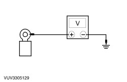
B2: CHECK THE POWER FEED TO THE GENERATOR
1
Disconnect Generator C863b.

2
Measure the voltage between generator C863b, circuit 30 (30-BA1 diesel), harness side and ground.

Is the voltage greater than 10 volts?
Yes
No
REPAIR circuit 30 (30-BA1 diesel). TEST the system for normal operation.
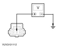
B3: CHECK CIRCUIT 30-BA8 (RD)
1
Connect Generator C863b.
2
Disconnect Generator C863a.

3
Measure the voltage between generator C863a pin 3, circuit 30-BA8 (RD), harness side and ground.

Is voltage greater than 10 volts?
Yes
No
REPAIR the circuit. TEST the system for normal operation.
B4: CHECK CIRCUIT 59-BA6 (GY)
1
Disconnect Generator C863c.

2
Measure the resistance between generator C863c, circuit 59-BA6 (GY) harness side and the generator C863a pin 2, circuit 59-BA6 (GY), harness side.

Is the resistance less than 5 ohms?
Yes
No
REPAIR the circuit. TEST the system for normal operation.
B5: CHECK THE CIRCUIT TO THE INSTRUMENT CLUSTER
1
Connect Generator C863c.

2
Measure the resistance between generator C863a pin 1, circuit 15S-BA9 (GN/BK) (15S-BA6 [GN/YE] diesel), harness side and ground.

Is the resistance greater than 10,000 ohms?
Yes
INSTALL a new generator. REFER to Section  414-02 Generator and Regulator. TEST the system for normal operation.
No
REFER to Section  413-01 Instrument Cluster.

PINPOINT TEST C : CHARGING SYSTEM WARNING INDICATOR IS OFF WITH THE IGNITION SWITCH IN THE RUN POSITION AND ENGINE OFF

TEST CONDITIONS DETAILS/RESULTS/ACTIONS
C1: CHECK THE CHARGING SYSTEM WARNING INDICATOR CIRCUIT
1
Ignition switch in position 0.
2
Disconnect Generator D+ C1885a.
3
Ignition switch in position II.

4
Measure the voltage between generator D+ C1885a pin 2, circuit 15S-DA1 (GN/YE), (15S-BA9 [GN/BK] vehicles with 2.5L engine) (15S-BA6 [GN/YE] vehicles with diesel engine), harness side and ground.

Is the voltage greater than 10 volts?
Yes
No
REFER to Section  413-01 Instrument Cluster.
C2: CHECK GENERATOR GROUND
1
Ignition switch in position 0.
2
Measure the resistance between the generator casing and ground.

Is the resistance less than 5 ohms?
Yes
INSTALL a new generator. REFER to Section  414-02 Generator and Regulator. TEST the system for normal operation.
No
CLEAN and TIGHTEN the ground connection as required. TEST the system for normal operation.

PINPOINT TEST D : RADIO INTERFERENCE

TEST CONDITIONS DETAILS/RESULTS/ACTIONS
D1: ISOLATE THE GENERATOR
1
Remove accessory drive belt. REFER to Section  303-05 Accessory Drive.
2
Ignition switch in position II.
3
Run engine for a few seconds with radio turned on.

Is interference still present?
Yes
No
CLEAN and TIGHTEN all mounting points. TEST the system for normal operation. If interference is still present, INSTALL a new generator. REFER to Section  414-02 Generator and Regulator.

Charging System - Vehicles Built From: 05-1999 > < Charging System