| PINPOINT TEST C : STOPLAMPS PERMANENTLY SWITCHED ON |
| TEST CONDITIONS | DETAILS/RESULTS/ACTIONS |
| C1: CHECK THE EQUIPMENT LEVEL |
| | 1 Check the equipment level. |
| | Is the vehicle equipped with an auxiliary warning system? Yes No |
| C2: DETERMINE THE CONDITIONS UNDER WHICH THE FAULT OCCURS |
| | 1 Ignition switch in position II. |
| | 2 Check the stoplamps. |
| | Are all the stoplamps permanently lit up? Yes No |
| C3: CHECK THE BULB CONTROL MODULE |
| | 1 Ignition switch in position 0. |
| | 2 Disconnect Bulb control module C466. |
| | 3 Ignition switch in position II. |
| | 4 Check the stoplamp. |
| | Is the affected stoplamp still lit up? Yes Left-hand stoplamp, vehicle equipped with trailer turn signal control module: GO to C4. All other stoplamps: LOCATE and RECTIFY short to B+ in circuit(s) connected to the bulb control module connector C466, pin 19 (left-hand stoplamp, vehicle without trailer turn signal control module), or pin 14 (right-hand stoplamp), or pin 5 (additional high-mounted stoplamp) with the aid of the Wiring Diagrams. CHECK operation of system No CHECK connection C466 and RENEW the bulb control module as necessary. RETEST system. |
| C4: CHECK TRAILER TURN SIGNAL CONTROL MODULE FOR SHORT TO B+ |
| | 1 Ignition switch in position 0. |
| | 2 Disconnect Trailer turn signal control module C2028. |
| | 3 Ignition switch in position II. |
| | 4 Check the left-hand stoplamp. |
| | Is the left-hand stoplamp permanently on? Yes LOCATE and RECTIFY short to B+ in circuit(s) connected to the bulb control module connector C466, pin 19 with the aid of the Wiring Diagrams. CHECK operation of system No RENEW the trailer turn signal control module. RETEST system. |
| C5: CHECK THE STOPLAMP SWITCH |
| | 1 Ignition switch in position 0. |
| | 2 Disconnect Stoplamp switch C444. |
| | 3 Ignition switch in position II. |
| | 4 Check the stoplamps. |
| | Are all the stoplamps permanently lit up? Yes No CHECK connection C444 and RENEW the stoplamp switch as necessary. RETEST system. |
| C6: CHECK THE BULB CONTROL MODULE |
| | 1 Ignition switch in position 0. |
| | 2 Disconnect Bulb control module C466. |
| | 3 Ignition switch in position II. |
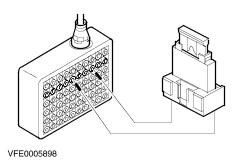
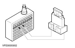
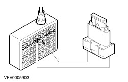
| | 4 Connect connector C466 to breakout box 29-001 using test lead no. 5 (33-004). |
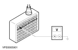
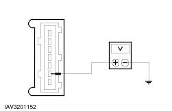
| | 5 Measure the voltage between the break-out box, pin 15 (bulb control module connector C466, pin 16, circuit 14S-WC40 (VT), wiring harness side) and ground. |
| | Is battery voltage displayed? Yes No CHECK connection C466 and RENEW the bulb control module as necessary. RETEST system. |
| C7: CHECK THE EQUIPMENT LEVEL |
| | 1 Check the equipment level. |
| | Is the vehicle equipped with a speed control system? Yes No |
| C8: CHECK THE CIRCUIT BETWEEN THE SPEED CONTROL CUT-OFF RELAY AND THE SPEED CONTROL MODULE |
| | 1 Ignition switch in position 0. |
| | 2 Disconnect Speed control cut-off relay C434. |
| | 3 Disconnect Speed control module C833. |
| | 4 Ignition switch in position II. |
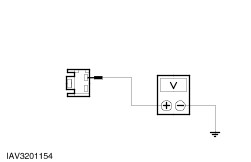
| | 5 Measure the voltage between speed control shut-off relay connector C434, circuit 14S-PG17 (VT/BU), wiring harness side and ground. |
| | Is battery voltage displayed? Yes LOCATE and RECTIFY short to B+ in circuit between speed control cut-off relay and speed control module. RETEST system. No |
| C9: CHECK THE CIRCUIT BETWEEN THE STOPLAMP SWITCH AND THE SPEED CONTROL CUT-OFF RELAY |
| | 1 Measure the voltage between speed control cut-off relay connector C434, circuit 14S-PG15 (VT), wiring harness side and ground. |
| | Is battery voltage displayed? Yes No |
| C10: CHECK THE SPEED CONTROL CUT-OFF RELAY |
| | 1 Ignition switch in position 0. |
| | 2 Connect Speed control cut-off relay C434. |
| | 3 Ignition switch in position II. |
| | 4 Check the stoplamps. |
| | Are the stoplamps permanently lit up? Yes CHECK connection C434 and RENEW the speed control cut-off relay as necessary. RETEST system. No CHECK connection C833 and RENEW the speed control module as necessary. RETEST system. |
| C11: CHECK CIRCUITS FOR SHORT TO B+ |
NOTE:Before connecting a module switch the ignition off, then connect the module and switch the ignition back on. |
| | 1 Ignition switch in position 0. |
| | 2 Connect Bulb control module C466. |
| | 3 Disconnect ABS module C1990. |
| | 4 Disconnect PCM C421 (petrol engines, except ZETEC-E with manual transmission) or C68 (diesel). |
| | 5 Disconnect Instrument panel auxiliary module C440. |
| | 6 Ignition switch in position II. |
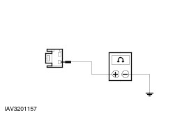
| | 7 Check the stoplamps. |
| | Are the stoplamps permanently lit up? Yes LOCATE and RECTIFY short to B+ in circuits connected to soldered connection S130 with the aid of the Wiring Diagrams. RETEST system. No Reconnect the modules individually in the reverse order. After connecting each module check whether the stoplamps are permanently lit up. As soon as the stoplamps light up RENEW the last module that was reconnected. RETEST system. |
| C12: CHECK THE STOPLAMP SWITCH |
| | 1 Ignition switch in position 0. |
| | 2 Disconnect Stoplamp switch C444. |
| | 3 Ignition switch in position II. |
| | 4 Check the stoplamps. |
| | Are the stoplamps permanently lit up? Yes No CHECK connection C444 and RENEW the stoplamp switch as necessary. RETEST system. |
| C13: CHECK THE EQUIPMENT LEVEL |
| | 1 Check the equipment level. |
| | Is the vehicle equipped with a speed control system? Yes No |
| C14: CHECK THE CIRCUIT BETWEEN THE SPEED CONTROL CUT-OFF RELAY AND THE SPEED CONTROL MODULE |
| | 1 Ignition switch in position 0. |
| | 2 Disconnect Speed control cut-off relay C434. |
| | 3 Disconnect Speed control module C833. |
| | 4 Ignition switch in position II. |
| | 5 Measure the voltage between speed control shut-off relay connector C434, circuit 14S-PG17 (VT/BU), wiring harness side and ground. |
| | Is battery voltage displayed? Yes LOCATE and RECTIFY short to B+ in circuit between speed control cut-off relay and speed control module. RETEST system. No |
| C15: CHECK THE CIRCUIT BETWEEN THE STOPLAMP SWITCH AND THE SPEED CONTROL CUT-OFF RELAY |
| | 1 Measure the voltage between speed control cut-off relay connector C434, circuit 14S-PG15 (VT), wiring harness side and ground. |
| | Is battery voltage displayed? Yes No |
| C16: CHECK THE SPEED CONTROL CUT-OFF RELAY |
| | 1 Ignition switch in position 0. |
| | 2 Connect Speed control cut-off relay C434. |
| | 3 Ignition switch in position II. |
| | 4 Check the stoplamps. |
| | Are the stoplamps permanently lit up? Yes CHECK connection C434 and RENEW the speed control cut-off relay as necessary. RETEST system. No CHECK connection C833 and RENEW the speed control module as necessary. RETEST system. |
| C17: CHECK CIRCUITS FOR SHORT TO B+ |
NOTE:Depending on equipment levels disconnect the following modules. |
NOTE:Before connecting a module switch the ignition off, then connect the module and switch the ignition back on. |
| | 1 Ignition switch in position 0. |
| | 2 Disconnect Trailer turn signal control module C2028. |
| | 3 Disconnect ABS module C1990. |
| | 4 Disconnect PCM C421 (petrol engines, except ZETEC-E with manual transmission) or C68 (diesel). |
| | 5 Disconnect Instrument panel auxiliary module C440. |
| | 6 Ignition switch in position II. |
| | 7 Check the stoplamps. |
| | Are the stoplamps permanently lit up? Yes LOCATE and RECTIFY short to B+ in circuits connected to soldered connection S130 with the aid of the Wiring Diagrams. RETEST system. No Reconnect the modules individually in the reverse order. After connecting each module check whether the stoplamps are permanently lit up. As soon as the stoplamps light up CHECK the last module that was reconnected and RENEW it as necessary. RETEST system. |