ford Workshop Repair Guides

Ford Workshop Service and Repair Manuals

Parking, Rear and License Lamps > < Stoplamps
Exterior Lighting - Turn Signal and Hazard Lamps Mondeo 1997 (08/1996-09/2000)
Diagnosis and Testing

Refer to Wiring Diagrams Section 417-01, for schematic and connector information.

Special Tool(s)

Terminal probe kit

29-011A

Breakout box

29-001

Test lead no. 5

33-003

Inspection and Verification

  1. Check customer concern.
  1. Visually check the system for obvious mechanical or electrical damage.

Visual Inspection Chart

Electrical
  • Fuse(s)
  • Wiring harness.
  • Bulb(s)
  • Connector
  • Switch
  • Headlamps
  • Rear lamp assembly
  1. Resolve any obvious causes or concerns found during the visual inspection before carrying out any further tests.
  1. If the concern persists, verify the symptom and continue with the symptom chart

Symptom Chart

Symptom Chart

Symptom Possible Sources Action
All turn signals inoperative
*
Fuse(s)
*
Turn signal relay
*
Multi-function switch
*
Circuit(s).
*
Central junction box (CJB)
*
Connector.
*
GO to Pinpoint Test ??.
All hazard lights inoperative
*
Fuse(s)
*
Multi-function switch
*
Turn signal relay
*
Circuit(s).
*
Battery junction box (BJB)
*
Connector.
*
GO to Pinpoint Test ??.
Left-hand turn signal inoperative
*
Circuit(s).
*
Multi-function switch
*
Central junction box (CJB)
*
GO to Pinpoint Test ??.
Right-hand turn signal inoperative
*
Circuit(s).
*
Multi-function switch
*
Central junction box (CJB)
*
GO to Pinpoint Test ??.
One turn signal inoperative
*
Circuit(s).
*
Central junction box (CJB)
*
Left/right-hand side turn signal lamp.
*
Left/right-hand front turn signal lamp.
*
Left-hand/right-hand rear lamp cluster.
*
Trailer turn signal control module.
*
Instrument cluster.
*
GO to Pinpoint Test ??.
One turn signal inoperative - trailer
*
Circuit(s).
*
Trailer socket.
*
Trailer turn signal control module.
*
REFER to Section  417-01 Exterior Lighting. Trailer socket.
Turn signals constantly flashing
*
Anti-theft system/double locking module
*
Multi-function switch
*
GO to Pinpoint Test ??.
All turn signals continuously lit up
*
Anti-theft system/double locking module
*
Left-hand turn signals continuously lit up
*
Circuit(s).
*
Trailer turn signal control module
*
Multi-function switch
*
Left-hand anti-theft warning flasher relay
*
Instrument cluster
*
Central junction box (CJB)
*
GO to Pinpoint Test ??.
Right-hand turn signals continuously lit up
*
Circuit(s).
*
Right-hand anti-theft warning flasher relay
*
Trailer turn signal control module
*
Multi-function switch
*
Instrument cluster
*
Central junction box (CJB)
*
GO to Pinpoint Test ??.

Pinpoint Testing

PINPOINT TEST A : ALL TURN SIGNALS INOPERATIVE

TEST CONDITIONS DETAILS/RESULTS/ACTIONS
A1: CHECK VOLTAGE SUPPLY
1
Ignition switch in position II.

2
Check the voltage between the input of fuse F23 in the central junction box (CJB) and ground.

Is battery voltage displayed?
Yes
No
LOCATE and RECTIFY open circuit between fuse F23 and battery positive terminal using the Wiring Diagrams. RETEST the system.
A2: CHECK FUSE F23 (15 A).

1
Check the voltage between the output of fuse F23 in the central junction box (CJB) and ground.

Is battery voltage displayed?
Yes
No
RENEW fuse F23 (15 A). If the fuse fails again, LOCATE and RECTIFY the short circuit using the Wiring Diagrams. RETEST the system.
A3: CHECK THE TURN SIGNAL RELAY AND THE MULTI-FUNCTION SWITCH
1
Ignition switch in position 0.
2
Disconnect Turn signal relay.
3
Ignition switch in position II.

4
Measure the voltage between the multi-function switch, turn signal relay socket (49) and ground.

Is battery voltage displayed ?
Yes
No
A4: CHECK THE VOLTAGE SUPPLY TO THE MULTI-FUNCTION SWITCH
1
Ignition switch in position 0.
2
Disconnect C459 Multi-function switch.
3
Ignition switch in position II.

4
Measure the voltage between multi-function switch connector C459, pin 11, circuit 14-LG25 (VT/BU) (15-LG25 (GN/BU) from 04/99), wiring harness side and ground.

Is battery voltage displayed ?
Yes
CHECK connector C459, RENEW the multi-function switch as necessary. RETEST the system.
No
A5: CHECK THE VOLTAGE SUPPLY TO THE MULTI-FUNCTION SWITCH

1
Measure the voltage between connector C372, pin 6 in the central junction box (CJB) and ground.

Is battery voltage displayed?
Yes
REPAIR break in circuit 14-LG25 (VT/BU) (or 15-LG25 (GN/BU) from 04/99) between the CJB and multi-function switch connector C459, pin 11. RETEST the system.
No
CHECK connection C372, as necessary RENEW the CJB. RETEST the system.
A6: MEASURE THE RESISTANCE AT THE MULTI-FUNCTION SWITCH
1
Ignition switch in position 0.

2
Measure the resistance between the multi-function switch, turn signal relay socket (31) and ground.

Is the resistance lower than 5 ohm?
Yes
No
A7: LOCATE THE GROUND FAULT
1
Disconnect C459 Multi-function switch.

2
Measure the resistance between the multi-function switch, connector C459, pin 7, circuit 31-LG25 (BK), wiring harness side and ground.

Is the resistance lower than 5 ohm?
Yes
CHECK connector C459, RENEW the multi-function switch as necessary. RETEST the system.
No
REPAIR the ground connection of the multi-function switch with the aid of the Wiring Diagrams. CHECK system operates correctly
A8: MEASURE THE RESISTANCE AT THE MULTI-FUNCTION SWITCH
1
Disconnect C459 Multi-function switch.
2
Operate the left-hand turn signal.

3
Measure the resistance at the multi-function switch between the turn signal relay socket (49A) and connector C459, pin 8, component side.

Is the resistance lower than 5 ohm?
Yes
RENEW the turn signal relay. RETEST the system.
No
RENEW the multi-function switch. RETEST the system.

PINPOINT TEST B : ALL HAZARD LIGHTS INOPERATIVE

TEST CONDITIONS DETAILS/RESULTS/ACTIONS
B1: CHECK THE VOLTAGE SUPPLY TO FUSE F12 (OR F7 FROM 04/99)
1
Ignition switch in position 0.

2
Measure the voltage between the input of fuse F12 (or F7 from 04/99) (15 A) (or 20 A from 03/97) at the battery junction box (BJB) and ground.

Is battery voltage displayed?
Yes
No
LOCATE and RECTIFY open circuit between fuse F12 (or F7 from 04/99) and battery positive terminal using the Wiring Diagrams. RETEST the system.
B2: CHECK FUSE F12 (OR F7 FROM 04/99)

1
Measure the voltage between the output of fuse F12 (or F7 from 04/99) (15 A) (or 20 A from 03/97) at the battery junction box (BJB) and ground.

Is battery voltage displayed?
Yes
No
RENEW fuse F12 (F7 from 04/99) (15A) (20A from 03/97). RETEST the system. If fuse F12 (or F7 from 04/99) blows again, LOCATE and RECTIFY short circuit using the Wiring Diagrams. RETEST the system.
B3: CHECK THE VOLTAGE SUPPLY TO THE MULTI-FUNCTION SWITCH
1
Disconnect C459 Multi-function switch.

2
Measure the voltage between the multi-function switch, connector C459, pin 10, circuit 29-LG27 (OG/BK), wiring harness side and ground.

Is battery voltage displayed?
Yes
No
LOCATE and RECTIFY the break in the circuit between fuse F12 (or F7 from 04/99) (15 A) (or 20 A from 03/97) and the multi-function switch with the aid of the Wiring Diagrams. RETEST the system.
B4: CHECK THE TURN SIGNAL RELAY AND THE MULTI-FUNCTION SWITCH
1
Disconnect Turn signal relay.
2
Connect C459 Multi-function switch.
3
Switch on the hazard warning lights.

4
Measure the voltage between the multi-function switch, turn signal relay socket (49) and ground.

Is battery voltage displayed ?
Yes
No
RENEW the multi-function switch. RETEST the system.
B5: MEASURE THE RESISTANCE AT THE MULTI-FUNCTION SWITCH

1
Measure the resistance between the multi-function switch, turn signal relay socket (31) and ground.

Is the resistance lower than 5 ohm?
Yes
CHECK connector C459, RENEW the multi-function switch as necessary. RETEST the system.
No
B6: LOCATE THE GROUND FAULT
1
Disconnect C459 Multi-function switch.

2
Measure the resistance between multi-function switch, connector C459, pin 7, circuit 31-LG25 (BK), wiring harness side and ground.

Is the resistance lower than 5 ohm?
Yes
No
REPAIR the ground connection of the multi-function switch with the aid of the Wiring Diagrams. RETEST the system.
B7: MEASURE THE RESISTANCE AT THE MULTI-FUNCTION SWITCH
1
Remove the multi-function switch.

2
Measure the resistance at the multi-function switch between the turn signal relay socket (49A) and connector C459, pin 8, component side.

Is the resistance lower than 1 ohm?
Yes
RENEW the flasher relay. RETEST the system.
No
CHECK connector C459, RENEW the multi-function switch as necessary. RETEST the system.

PINPOINT TEST C : LEFT-HAND TURN SIGNAL INOPERATIVE

TEST CONDITIONS DETAILS/RESULTS/ACTIONS
C1: FAULT LOCALIZATION
1
Switch on the hazard warning lights.

Do the left-hand turn signal lamps work?
Yes
CHECK connector C459, RENEW the multi-function switch as necessary. RETEST the system.
No
C2: CHECK CIRCUIT 49S-LG1 FOR CONTINUITY
1
Ignition switch in position 0.
2
Disconnect Central junction box (CJB)C372.
3
Disconnect C459 Multi-function switch.

4
Measure the resistance between the central junction box (CJB), connector C372, circuit 49S-LG1 (BU), pin 9, wiring harness side, and the multi-function switch, connector C459, pin 8 wiring harness side.

Is the resistance lower than 5 ohm?
Yes
CHECK connection C372, if necessary RENEW the CJB. RETEST the system.
No
REPAIR break in circuit 49S-LG1 (BU). RETEST the system.

PINPOINT TEST D : RIGHT-HAND TURN SIGNAL INOPERATIVE

TEST CONDITIONS DETAILS/RESULTS/ACTIONS
D1: FAULT LOCALIZATION
1
Switch on the hazard warning lights.

Do the right-hand turn signal lamps work?
Yes
CHECK connector C459, RENEW the multi-function switch as necessary. RETEST the system.
No
D2: CHECK CIRCUIT 49S-LG2 FOR CONTINUITY
1
Ignition switch in position 0.
2
Disconnect Central junction box (CJB) C372.
3
Disconnect C459 Multi-function switch.

4
Measure the resistance between the central junction box (CJB), connector C372, pin 8, circuit 49S-LG2 (BU/RD), wiring harness side, and the multi-function switch, connector C459, pin 9, circuit 49S-LG2 (BU/RD), wiring harness side.

Is the resistance lower than 5 ohm?
Yes
CHECK connection C372, if necessary RENEW the CJB. RETEST the system.
No
REPAIR break in circuit 49S-LG2 (BU/RD). RETEST the system.

PINPOINT TEST E : ONE TURN SIGNAL INOPERATIVE

TEST CONDITIONS DETAILS/RESULTS/ACTIONS
E1: FAULT LOCALIZATION
1
Ignition switch in position 0.
2
Switch on the hazard warning lights.

Is one of the left-hand turn signal lamps inoperative?
Yes
No
Is one of the right-hand turn signal lamps inoperative? GO to E13.
E2: FAULT LOCALIZATION
1
Check the turn signal lamps.

Are the front and side turn signal lamps on the left-hand side inoperative?
Yes
from 03/97: RENEW the central junction box. RETEST the system.
up to 03/97: GO to E3.
No
Left-hand side turn signal lamp inoperative: GO to E4.
Left-hand front turn signal lamp inoperative: GO to E6.
Left-hand rear turn signal lamp (rear lamp assembly) inoperative: GO to E8.
Display light in the instrument cluster (left-hand turn signal) inoperative: GO to E12.
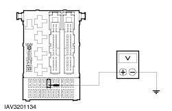
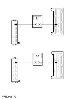
E3: CHECK CIRCUIT 49-LG3 FOR CONTINUITY
1
Switch off the hazard warning lights.
2
Disconnect Central junction box (CJB)C369.
3
Disconnect Left-hand side turn signal lamp C753.

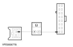
4
Measure the resistance between the central junction box (CJB), connector C369, pin 14, circuit 49-LG3 (BU), wiring harness side, and the left-hand side turn signal lamp, connector C753, pin 2, circuit 49-LG3 (BU), wiring harness side.

Are less than 5 ohms registered?
Yes
CHECK connection C369, if necessary RENEW the CJB. RETEST the system.
No
REPAIR break in circuit 49-LG3 (BU). RETEST the system.
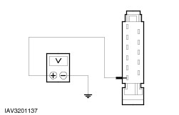
E4: CHECK CIRCUIT 49-LG13 FOR CONTINUITY
1
Switch off the hazard warning lights.
2
Disconnect Left-hand side turn signal lamp C753.
3
Switch on the hazard warning lights.

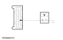
4
Using an analogue voltmeter, measure the voltage between the side left-hand turn turn signal lamp connector C753, pin 2, circuit 49-LG13 (BU/RD), wiring harness side and ground.

Does the meter reading alternate between battery voltage and 0 V?
Yes
No
REPAIR break in circuit 49-LG13. RETEST the system.
E5: CHECK GROUND CIRCUIT 31-LG13 FOR CONTINUITY
1
Switch off the hazard warning lights.

2
Measure the resistance between the left-hand side turn signal lamp, connector C753, pin 1, circuit 31-LG13 (BK), wiring harness side and ground.

Is the resistance less than 5 ohm?
Yes
After checking the bulb RENEW the left-hand side turn signal lamp. RETEST the system.
No
REPAIR break in ground circuit 31-LG13. RETEST the system.
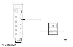
E6: CHECK CIRCUIT 49-LG11 FOR CONTINUITY
1
Switch off the hazard warning lights.
2
Disconnect Left-hand front turn signal lamp C713 or C2038.
3
Switch on the hazard warning lights.

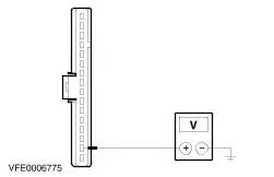
4
Using an analogue voltmeter, measure the voltage between the left-hand front turn signal lamp, connector C713 (or C2038 from 08/98), pin 2, circuit 49-LG11 (BU/OG), wiring harness side and ground.

Does the meter reading alternate between battery voltage and 0 V?
Yes
No
REPAIR break in circuit 49-LG11. RETEST the system.
E7: CHECK GROUND CIRCUIT 31-LG11 FOR CONTINUITY
1
Switch off the hazard warning lights.

2
Measure the resistance between the left-hand front turn signal lamp, connector C713 (C2038 from 08/98), pin 1, circuit 31-LG11 (BK), wiring harness side and ground.

Is the resistance less than 5 ohm?
Yes
After checking the bulb RENEW the left-hand front turn signal lamp. RETEST the system.
No
REPAIR break in ground circuit 31-LG11 (BK). RETEST the system.
E8: CHECK THE CIRCUIT TO THE LEFT-HAND REAR LAMP ASSEMBLY FOR OPEN CIRCUIT
1
Switch off the hazard warning lights.
2
Disconnect Left-hand rear lamp cluster C446 or C2021.
3
Switch on the hazard warning lights.

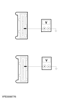
4
Using an analogue voltmeter, measure the voltage between the left-hand rear turn signal lamp (rear lamp assembly), connector C446 (or C2021 on vehicles with a trailer coupling), pin 3, wiring harness side and ground.

Does the meter reading alternate between battery voltage and 0 V?
Yes
No
Vehicles with a trailer turn signal control module: GO to E10.
All other vehicles: REPAIR break in circuit 49-LG12 (BU) or circuit (BU). RETEST the system.
E9: CHECK THE GROUND CIRCUIT OF THE LEFT-HAND REAR TURN SIGNAL LAMP (REAR LAMP ASSEMBLY)

1
Measure the resistance between the left-hand rear turn signal lamp (rear lamp assembly), connector C446 (or C2021 on vehicles with a trailer coupling), pin 4 (or pin 6 on estate), wiring harness side and ground.

Is the resistance lower than 5 ohm?
Yes
After checking the bulb, RENEW the left-hand rear lamp assembly. RETEST the system.
No
Vehicles with a trailer coupling: REPAIR circuit BN. RETEST the system.
All other vehicles: REPAIR circuit 31-LF11 (BK) RETEST the system.
E10: CHECK THE CIRCUIT TO THE TRAILER TURN SIGNAL CONTROL MODULE (LEFT-HAND REAR LAMP ASSEMBLY) FOR OPEN CIRCUIT
1
Switch off the hazard warning lights.
2
Disconnect Trailer turn signal control module C2028.
3
Switch on the hazard warning lights.

4
Using an analogue voltmeter, measure the voltage between the trailer turn signal control module, connector C2028, pin 5, circuit (WH), wiring harness side and ground.

Does the meter reading alternate between battery voltage and 0 V?
Yes
No
REPAIR break in circuit (WH) or circuit 49S-LG12 (BU). RETEST the system.
E11: CHECK CIRCUIT GY/WH FOR CONTINUITY

1
Measure the resistance between trailer turn signal control module, connector C2028, pin 8, wiring harness side and left-hand rear lamp assembly, connector C2021, pin 3, circuit (GY/WH), wiring harness side.

Is the resistance lower than 5 ohm?
Yes
CHECK connection C2028 and RENEW the trailer turn signal control module as necessary. TEST the system again.
No
REPAIR break in circuit (GY/WH). RETEST the system.
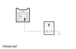
E12: CHECK CIRCUIT 29S-LG15 FOR CONTINUITY
1
Switch off the hazard warning lights.
2
Disconnect Instrument cluster C808a.
3
Switch on the hazard warning lights.

4
Using an analogue voltmeter, measure the voltage between instrument cluster connector C808a, circuit 29S-LG15 (OG/BK), wiring harness side and ground.

Does the meter reading alternate between battery voltage and 0 V?
Yes
After checking the bulb RENEW the instrument cluster. RETEST the system.
No
REPAIR break in circuit 29S-LG15 (OG/BK). RETEST the system.
E13: FAULT LOCALIZATION
1
Check the turn signal lamps.

Are the front and side turn signal lamps on the right-hand side inoperative?
Yes
from 03/97: RENEW the central junction box. RETEST the system.
up to 03/97: GO to E14.
No
Right-hand side turn signal lamp inoperative: GO to E15.
Right-hand front turn signal lamp inoperative: GO to E17.
Right-hand rear turn signal lamp inoperative: GO to E19.
Display light in the instrument cluster (right-hand turn signal) inoperative: GO to E23.
E14: CHECK CIRCUIT 49-LG4 FOR CONTINUITY
1
Switch off the hazard warning lights.
2
Disconnect Central junction box (CJB) C369.
3
Disconnect Right-hand side turn signal lamp C754.

4
Measure the resistance between the central junction box (CJB), connector C369, pin 16, circuit 49-LG4 (BU/RD), wiring harness side, and the right-hand side turn signal lamp, connector C754, pin 2, circuit 49-LG20 (BU/WH), wiring harness side.

Is the resistance lower than 5 ohm?
Yes
CHECK connection C369, if necessary RENEW the CJB. RETEST the system.
No
REPAIR break in circuit 49-LG4 (BU/RD). RETEST the system.
E15: CHECK CIRCUIT 49-LG20 FOR CONTINUITY
1
Switch off the hazard warning lights.
2
Disconnect Right-hand side turn signal lamp C754.
3
Switch on the hazard warning lights.

4
Using an analogue voltmeter, measure the voltage between the side right-hand turn turn signal lamp connector C754, pin 2, circuit 49-LG20 (BU/WH), wiring harness side and ground.

Does the meter reading alternate between battery voltage and 0 V?
Yes
No
REPAIR break in circuit 49-LG20. RETEST the system.
E16: CHECK GROUND CIRCUIT 31-LG20 FOR CONTINUITY
1
Switch off the hazard warning lights.

2
Measure the resistance between the right-hand side turn signal lamp, connector C754, pin 1, circuit 31-LG20 (BK), wiring harness side and ground.

Are less than 5 ohms registered?
Yes
After checking the bulb RENEW the right-hand side turn signal lamp. RETEST the system.
No
REPAIR break in ground circuit 31-LG20 (BK). RETEST the system.
E17: CHECK CIRCUIT 49-LG18 FOR CONTINUITY
1
Switch off the hazard warning lights.
2
Disconnect Right-hand front turn signal lamp C714 or C2039.
3
Switch on the hazard warning lights.

4
Using an analogue voltmeter, measure the voltage between the right-hand front turn signal lamp, connector C714 (or C2039 from 08/98), pin 2, circuit 49-LG18 (BU), wiring harness side and ground.

Does the meter reading alternate between battery voltage and 0 V?
Yes
No
REPAIR break in circuit 49-LG18 (BU). RETEST the system.
E18: CHECK GROUND CIRCUIT 31-LG18 FOR CONTINUITY
1
Switch off the hazard warning lights.

2
Measure the resistance between the right-hand front turn signal lamp, connector C714 (C2039 from 08/98), pin 1, circuit 31-LG18 (BK), wiring harness side and ground.

Are less than 5 ohms registered?
Yes
After checking the bulb RENEW the right-hand front turn signal lamp. RETEST the system.
No
REPAIR break in ground circuit 31-LG18 (BK). RETEST the system.
E19: CHECK CIRCUIT 49-LG19 FOR CONTINUITY
1
Switch off the hazard warning lights.
2
Disconnect Right-hand rear lamp assembly C447 or C2017.
3
Switch on the hazard warning lights.

4
Using an analogue voltmeter, measure the voltage between the right-hand rear turn signal lamp (rear lamp assembly), connector C447 (or C2017 on vehicles with a trailer coupling), pin 5 (or pin 3 on estate), wiring harness side and ground.

Does the meter reading alternate between battery voltage and 0 V?
Yes
No
Vehicles with a trailer turn signal control module: GO to E21.
All other vehicles: REPAIR break in circuit 49-LG19 (BU/RD) (or BU/RD). RETEST the system.
E20: TEST THE GROUND CIRCUIT OF THE REAR RIGHT TURN SIGNAL LAMP (REAR LAMP ASSEMBLY)

1
Measure the resistance between the right-hand rear lamp assembly, connector C447 (or connector C2017 on vehicles with a trailer coupling), pin 4 (or pin 6 on estate), wiring harness side and ground.

Is the resistance less than 5 ohm?
Yes
After checking the bulb, RENEW the right-hand rear lamp assembly. RETEST the system.
No
Vehicles with a trailer coupling: REPAIR circuit GN. RETEST the system.
All other vehicles: REPAIR circuit 31-LF20 (BK). RETEST the system.
E21: TEST CIRCUIT GN OR 49-LG19 FOR BREAK
1
Switch off the hazard warning lights.
2
Disconnect Trailer turn signal control module C2028.
3
Switch on the hazard warning lights.

4
Using an analogue voltmeter, measure the voltage between the trailer turn signal control module, connector C2028, pin 6, circuit (GN), wiring harness side and ground.

Does the meter reading alternate between battery voltage and 0 V?
Yes
No
REPAIR break in circuit GN or circuit 49-LG19 (BU/RD). RETEST the system.
E22: CHECK FOR BREAK IN CIRCUIT GN/YE OR BU/RD

1
Measure the resistance between trailer turn signal control module, connector C2028, pin 10, wiring harness side and right-hand rear lamp assembly, connector C2017, pin 5 (pin 3 on estate), circuit (GN/YE) or (BU/RD), wiring harness side.

Is the resistance less than 5 ohm?
Yes
CHECK connection C2028 and RENEW the trailer turn signal control module as necessary. RETEST the system.
No
REPAIR break in circuit (GN/YE) or (BU/RD). RETEST the system.
E23: CHECK CIRCUIT 29S-LG22 FOR CONTINUITY
1
Switch off the hazard warning lights.
2
Disconnect Instrument cluster C808a.
3
Switch on the hazard warning lights.

4
Using an analogue voltmeter, measure the voltage between the connector of the instrument cluster display light (right-hand turn signal) C808a, circuit 29S-LG22 (OG/GN), wiring harness side and ground.

Does the meter reading alternate between battery voltage and 0 V?
Yes
After checking the bulb RENEW the instrument cluster. RETEST the system.
No
REPAIR break in circuit 29S-LG22 (OG/GN). RETEST the system.

PINPOINT TEST F : TURN SIGNALS CONSTANTLY FLASHING

TEST CONDITIONS DETAILS/RESULTS/ACTIONS
F1: CHECK EQUIPMENT LEVEL OF VEHICLE
1
Determine the equipment level of the vehicle.

Is the vehicle equipped with an anti-theft/double-locking system?
Yes
No
RENEW the multi-function switch. RETEST the system.
F2: CHECK THE MULTI-FUNCTION SWITCH
1
Ignition switch in position 0.
2
Disconnect C459 Multi-function switch.
3
Ignition switch in position II.
4
Check the turn signal lamps.

Are all turn signal lamps permanently lit up?
Yes
No
RENEW the multi-function switch. RETEST the system.

PINPOINT TEST G : LEFT-HAND TURN SIGNALS CONTINUOUSLY LIT UP

TEST CONDITIONS DETAILS/RESULTS/ACTIONS
G1: FAULT LOCALIZATION
NOTE:
NOTE:Vehicles equipped with a tow bar should be tested without the trailer.
1
Ignition switch in position 0.
2
Disconnect Central junction box (CJB)C372.
3
Ignition switch in position II.
4
Check the left-hand turn signal lamps.

Are all turn signal lamps on the left-hand side permanently lit up?
Yes
No
G2: CHECK THE MULTI-FUNCTION SWITCH
1
Ignition switch in position 0.
2
Disconnect C459 Multi-function switch.
3
Connect Central junction box (CJB) C372.
4
Ignition switch in position II.
5
Check the left-hand turn signal lamps.

Are all turn signal lamps on the left-hand side permanently lit up?
Yes
Vehicles with anti-theft warning system: GO to G3.
Vehicles without anti-theft warning system: LOCATE and RECTIFY short circuit to B+ in circuit 49S-LG1 (BU). RETEST the system.
No
RENEW the multi-function switch. RETEST the system.
G3: CHECK THE LEFT-HAND ANTI-THEFT WARNING FLASHER RELAY
1
Ignition switch in position 0.
2
Disconnect Anti-theft warning flasher relay (left-hand side C450) or C449.
3
Ignition switch in position II.
4
Check the left-hand turn signal lamps.

Are all turn signal lamps on the left-hand side permanently lit up?
Yes
LOCATE and RECTIFY short in circuit 49S-LG1 (BU), 49S-MB23 (BU/OG) (49S-GL23 (BU/OG) from 04/99) or 49-MB23 (BU/OG) (49-GL1 (BU) from 04/99). RETEST the system.
No
RENEW the left-hand anti-theft warning flasher relay. RETEST the system.
G4: CHECK INSTRUMENT CLUSTER AND CIRCUIT 29S-LG15 FOR SHORT CIRCUIT TO B+
1
Ignition switch in position 0.
2
Disconnect Central junction box (CJB)C362.
3
Ignition switch in position II.
4
Check the left-hand turn signal lamps.

Are all turn signal lamps on the left-hand side permanently lit up?
Yes
No
G5: CHECK CIRCUIT 29S-LG15 FOR SHORT CIRCUIT TO B+
1
Ignition switch in position 0.
2
Disconnect Instrument cluster C808a.
3
Connect Central junction box (CJB) C362.
4
Ignition switch in position II.
5
Check the left-hand turn signal lamps.

Are all turn signal lamps on the left-hand side permanently lit up?
Yes
LOCATE and RECTIFY short circuit in circuit 29S-LG15 (OG/BK). RETEST the system.
No
RENEW the instrument cluster. RETEST the system.
G6: CHECK CIRCUIT 49-LG13 OR 49-LG11 (OR 49-LG3 UP TO 03/97) FOR SHORT TO B+
1
Ignition switch in position 0.
2
Connect Central junction box (CJB)C362.
3
Disconnect Central junction box (CJB) C369.
4
Ignition switch in position II.
5
Check the left-hand turn signal telltale.

Does the left-hand turn signal telltale light up continuously?
Yes
No
REPAIR short in circuit 49-LG13 (BU/RD) or 49-LG11 (BU/OG) (or 49-LG3 (BU) before 03/97). RETEST the system.
G7: CHECK CIRCUIT 49-LG12 FOR SHORT TO B+
1
Ignition switch in position 0.
2
Disconnect Central junction box (CJB)C367.
3
Ignition switch in position II.
4
Check the left-hand turn signal telltale.

Does the left-hand turn signal telltale light up continuously?
Yes
RENEW the CJB. RETEST the system.
No
Vehicles without a trailer coupling: LOCATE and RECTIFY short circuit in circuit 49-LG12 (BU). RETEST the system.
Vehicles with a trailer coupling, but without trailer turn signal control module: LOCATE and RECTIFY short in circuit 49-LG12 (BU) or circuit BU. RETEST the system.
Vehicles with a trailer coupling and trailer turn signal control module: GO to G8.
G8: CHECK THE CIRCUIT TO THE TRAILER TURN SIGNAL CONTROL MODULE (LEFT-HAND REAR LAMP ASSEMBLY) FOR SHORT TO B+
1
Ignition switch in position 0.
2
Disconnect Trailer turn signal control module C2028.
3
Ignition switch in position II.
4
Check the left-hand rear turn signal lamp (rear lamp assembly).

Does the left-hand rear turn signal light up continuously?
Yes
LOCATE and RECTIFY short in circuit GY/WH between trailer turn signal control module and left-hand rear lamp assembly. RETEST the system.
No
G9: CHECK CIRCUIT 49-LG12 OR (WH) FOR SHORT TO B+

1
Measure the voltage between the trailer turn signal control module C2028, pin 5, circuit (WH), wiring harness side and ground.

Is battery voltage displayed?
Yes
LOCATE and RECTIFY short circuit in circuit 49-LG12 (BU) or (WH). RETEST the system.
No
RENEW the trailer turn signal control module. RETEST the system.

PINPOINT TEST H : RIGHT-HAND TURN SIGNALS CONTINUOUSLY LIT UP

TEST CONDITIONS DETAILS/RESULTS/ACTIONS
H1: FAULT LOCALIZATION
NOTE:
NOTE:Vehicles equipped with a tow bar should be tested without the trailer.
1
Ignition switch in position 0.
2
Disconnect Central junction box (CJB) C372.
3
Ignition switch in position II.
4
Check the right-hand turn signal lamps.

Are all turn signal lamps on the right-hand side permanently lit up?
Yes
No
H2: CHECK THE MULTI-FUNCTION SWITCH
1
Ignition switch in position 0.
2
Disconnect C459 Multi-function switch.
3
Connect Central junction box (CJB)C372.
4
Ignition switch in position II.
5
Check the right-hand turn signal lamps.

Are all turn signal lamps on the right-hand side permanently lit up?
Yes
Vehicles with anti-theft warning system: GO to H3.
Vehicles without anti-theft warning system: LOCATE and RECTIFY short to B+ in circuit 49S-LG2 (BU/RD). RETEST the system.
No
RENEW the multi-function switch. RETEST the system.
H3: TEST ANTI-THEFT SYSTEM RIGHT-HAND FLASHER RELAY
1
Ignition switch in position 0.
2
Disconnect Right-hand anti-theft warning flasher relay C449C449.
3
Ignition switch in position II.
4
Check the right-hand turn signal lamps.

Are all turn signal lamps on the right-hand side permanently lit up?
Yes
LOCATE and RECTIFY short in circuit 49S-LG2 (BU/RD), 49S-MB25 (BU/WH) (or 49S-GL25 (BU/WH) from 04/99) or 49-MB25 (BU/WH) (or 49-GL2 (BU/RD) from 04/99). RETEST the system.
No
RENEW the right-hand anti-theft warning flasher relay RETEST the system.
H4: CHECK INSTRUMENT CLUSTER AND CIRCUIT 29S-LG22 FOR SHORT TO B+
1
Ignition switch in position 0.
2
Disconnect Central junction box (CJB) C362.
3
Ignition switch in position II.
4
Check the right-hand turn signal lamps.

Are all turn signal lamps on the right-hand side permanently lit up?
Yes
No
H5: CHECK CIRCUIT 29S-LG22 FOR SHORT TO B+
1
Ignition switch in position 0.
2
Disconnect Instrument cluster C808a.
3
Connect Central junction box (CJB)C362.
4
Ignition switch in position II.
5
Check the right-hand turn signal lamps.

Are all turn signal lamps on the right-hand side permanently lit up?
Yes
LOCATE and RECTIFY short circuit in circuit 29S-LG22 (OG/GN). RETEST the system.
No
RENEW the instrument cluster. RETEST the system.
H6: CHECK CIRCUIT 49-LG20 AND 49-LG18 (AND 49-LG4 UP TO 03/97) FOR SHORT TO B+
1
Ignition switch in position 0.
2
Connect Central junction box (CJB) C362.
3
Disconnect Central junction box (CJB)C369.
4
Ignition switch in position II.
5
Check the right-hand turn signal telltale.

Does the right-hand turn signal telltale light up continuously?
Yes
No
LOCATE and RECTIFY short circuit in circuit 49-LG20 (BU/WH) or 49-LG18 (BU) (or 49-LG4 (BU/RD) prior to 03/97). RETEST the system.
H7: CHECK CIRCUIT 49-LG19 FOR SHORT TO B+
1
Ignition switch in position 0.
2
Disconnect Central junction box (CJB) C367.
3
Ignition switch in position II.
4
Check the right-hand turn signal telltale.

Does the right-hand turn signal telltale light up continuously?
Yes
RENEW the CJB. RETEST the system.
No
Vehicles without a trailer coupling: LOCATE and RECTIFY short circuit in circuit 49-LG19 (BU/RD). RETEST the system.
Vehicles with a trailer coupling, but without trailer turn signal control module: LOCATE and RECTIFY short in circuit 49-LG19 (BU/RD) or circuit (BU/RD). RETEST the system.
Vehicles with a trailer coupling and trailer turn signal control module: GO to H8.
H8: CHECK THE CIRCUIT TO THE TRAILER TURN SIGNAL CONTROL MODULE (RIGHT-HAND REAR LAMP ASSEMBLY) FOR SHORT TO B+
1
Ignition switch in position 0.
2
Disconnect Trailer turn signal control module C2028.
3
Ignition switch in position II.
4
Check the right-hand rear turn signal lamp (rear lamp assembly).

Does the right-hand rear turn signal light up continuously?
Yes
LOCATE and RECTIFY short in circuit (GN/YE) or (BU/RD) between trailer turn signal control module and right-hand rear lamp assembly. RETEST the system.
No
H9: CHECK CIRCUIT 49-LG19 OR (GN) FOR SHORT TO B+

1
Measure the voltage between the trailer turn signal control module C2028, pin 6, circuit (GN), wiring harness side and ground.

Is battery voltage displayed?
Yes
LOCATE and RECTIFY short circuit in circuit 49-LG19 (BU/RD) or (GN). RETEST the system.
No
RENEW the trailer turn signal control module. RETEST the system.

Parking, Rear and License Lamps > < Stoplamps