| Diagnosis and Testing - Verify the customer concern.
- Visually inspect for obvious signs of mechanical or electrical damage.
Visual Inspection Chart | Mechanical | Electrical | - Mechanism(s)
- Misaligned door(s)
| - Battery
- Fuse(s)
- Circuit
- Door lock actuator
| - If an obvious cause for an observed or reported concern is found, correct the cause (if possible) before proceeding to the next step.
- If the concern is not visually evident, verify the symptom and refer to the Symptom Chart.
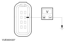
Symptom Chart | Symptom | Possible Sources | Action | | One door lock inoperative | * Fuse(s). * Circuit(s). * Door lock actuator. | * GO to Pinpoint Test ??. . | | All door locks inoperative | * Battery. * Fuse(s). * Circuit(s). * Door lock actuator. | * GO to Pinpoint Test ??. . | | Liftgate lock inoperative | * Fuse(s). * Circuit(s). * Liftgate lock actuator. | * GO to Pinpoint Test ??. . | Pinpoint Tests | PINPOINT TEST A : ONE DOOR LOCK INOPERATIVE | | TEST CONDITIONS | DETAILS/RESULTS/ACTIONS | | A1: CHECK OPERATION OF SUSPECT DOOR LOCK | | | 1 Manually operate the inoperative door lock. | | | 2 Check for stuck or binding condition. | | | Is the lock stuck or binding? Yes REPAIR the condition. If necessary INSTALL a new component. No | | A2: CHECK DOOR LOCK ACTUATOR FOR LOCK OPERATION | | | 1 Ignition switch in position 0. | | | 2 Disconnect Inoperative Door Lock Actuator. | | | 3 Measure the voltage between the inoperative door lock actuator electrical connector and ground while actuating the door locks to the lock position. - Front door - door lock actuator C1969/C1970 pin 2, circuit 32-AA59 (WH/BK), and ground.
- Rear door - door lock actuator C1971/C1972 pin 2, circuit 32-AA59 (WH/BK), and ground.
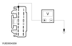
| | | Is the voltage greater than 10 volts? Yes No REPAIR circuit 32-AA59 (WH/BK). TEST the system for normal operation. | | A3: CHECK DOOR LOCK ACTUATOR FOR UNLOCK OPERATION | | | 1 Measure the voltage between the inoperative door lock actuator electrical connector and ground while actuating the door locks to the unlock position: - Front door - door lock actuator C1969/C1970 pin 1, circuit 33-AA59 (YE/BK), and ground.
- Rear door - door lock actuator C1971/C1972 pin 1, circuit 33-AA59 (YE/BK), and ground.
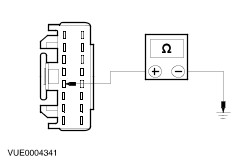
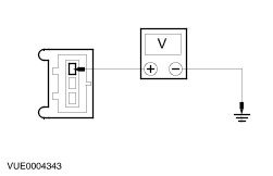
| | | Is the voltage greater than 10 volts? Yes No REPAIR circuit 33-AA59 (YE/BK). TEST the system for normal operation. | | PINPOINT TEST B : ALL DOOR LOCKS INOPERATIVE | | TEST CONDITIONS | DETAILS/RESULTS/ACTIONS | | B1: CHECK FUSE 25 (20A) | | | 1 CHECK Fuse 25 (20A). | | | 2 CHECK Fuse 30 (7.5A). | | | Is the fuse OK? Yes No INSTALL a new fuse. TEST the system for normal operation. If fuse fails again, CHECK for short to ground. | | B2: CHECK ANTI-THEFT/CENTRAL LOCKING MODULE FOR BATTERY VOLTAGE | | | 1 Disconnect Anti-Theft/Central Locking Module C1966a. | | | 2 Measure the voltage between the anti-theft/central locking module C1966a pin 1, circuit 29-AA17 (OG/WH), harness side and ground. | | | Is the voltage greater than 10 volts? Yes No REPAIR circuit 29-AA17 (OG/WH). TEST the system for normal operation. | | B3: CHECK ANTI-THEFT/CENTRAL LOCKING MODULE FOR IGNITION VOLTAGE | | | 1 Measure the voltage between the anti-theft/central locking module C1966a pin 10, circuit 14-AA17 (VT/WH), harness side and ground. | | | Is the voltage greater than 10 volts? Yes No REPAIR circuit 14-AA17 (VT/WH). TEST the system for normal operation. | | B4: CHECK ANTI-THEFT/CENTRAL LOCKING MODULE FOR GROUND | | | 1 Measure resistance between anti-theft/central locking module C1966a pin 5, circuit 31-AA17 (BK), harness side and ground. | | | Is resistance less than 5 ohms? Yes No REPAIR circuit 31-AA17 (BK). TEST the system for normal operation. | | PINPOINT TEST C : THE LIFTGATE LOCK - INOPERATIVE | | TEST CONDITIONS | DETAILS/RESULTS/ACTIONS | | C1: CHECK LIFTGATE LOCK ACTUATOR FOR VOLTAGE | | | 1 Disconnect Liftgate Lock Actuator C844. | | | 2 Measure the voltage between the liftgate lock actuator C844 pin 3, circuit 29S-AA27 (OG/BK), harness side and ground. | | | Is voltage greater than 10 volts? Yes No REPAIR circuit 29S-AA27 (OG/BK). TEST the system for normal operation. | | C2: CHECK LIFTGATE LOCK ACTUATOR FOR GROUND | | | 1 Measure the resistance between the liftgate lock actuator C844 pin 1, circuit 31-AA27 (BK), harness side and ground. | | | Is the resistance less than 5 ohms? Yes No REPAIR circuit 31-AA27 (BK). TEST the system for normal operation. | | C3: CHECK THE LIFTGATE LOCK ACTUATOR | | | 1 Measure the resistance between the liftgate lock actuator C844 pin 3, circuit 29S-AA27 (OG/BK), harness side and pin 1, circuit 31-AA27 (BK), harness side and between the liftgate lock actuator C844 pin 3, circuit 29S-AA27 (OG/BK), harness side and pin 2. | | | Is the resistance between pin 3 and pin 1 between 0.5 and 9 ohms and less than 5 ohms between pin 3 and pin 2? Yes REPAIR circuit 29S-AA27 (OG/BK). TEST the system for normal operation. No INSTALL a new liftgate lock actuator. TEST the system for normal operation. | | |