| Removal and Installation Special Tool(s) | | Alignment Pins, Subframe 205-316 (15-097A) | General Equipment Materials Name Specification Anti-seize grease SAM-1C9107-A Removal All vehicles | | -
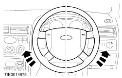
NOTE:Make sure the road wheels are in the straight ahead position. Centralize the steering and lock it in position. | | | -
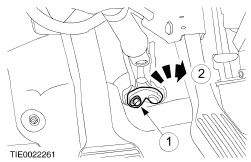
Detach the steering column shaft from the steering column flexible coupling. - Remove the retaining bolt.
- Rotate the clamp plate.
| | | -
Using suitable pins, support the radiator on the radiator grill opening panel (left-hand side shown). | Vehicles with diesel engines | | -
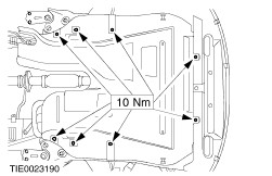
Remove the engine undershield. | All vehicles | | -
Remove the splash shield. | | | -
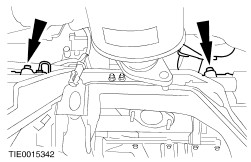
Remove the radiator support brackets retaining bolts (left-hand side shown). | | | -
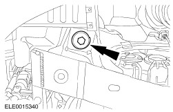
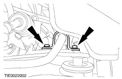
Remove the coolant hose support bracket. | | | -
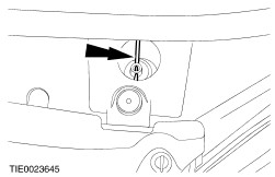
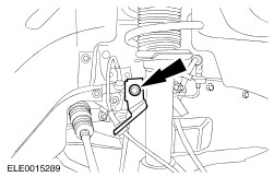
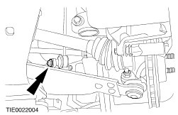
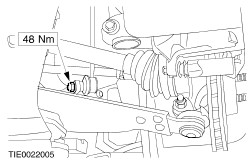
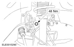
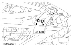
NOTE:Use a 5 mm Allen key to prevent the ball joint from rotating. Detach the stabilizer bar connecting links from the suspension struts (right-hand side shown). | Vehicles with 1.8L, 2.0L or diesel engine Vehicles with 2.5L engine All vehicles | | -
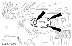
Remove the engine rear support insulator. | | | -
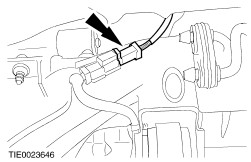
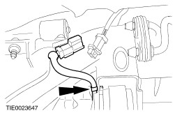
Disconnect the catalyst monitor sensor electrical connector. | | | -
Detach the catalyst monitor sensor wiring harness from the subframe. | | | -
Detach the radiator cooling fan wiring harness from the subframe. | Vehicles with xenon headlamps | | -
Detach the headlamp leveling sensor wiring harness from the subframe. | All vehicles | | -
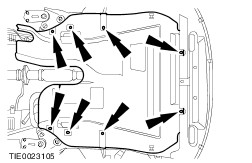
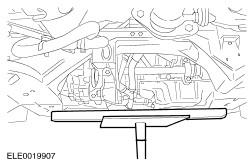
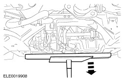
Using two suitable wooden blocks and suitable transmission jack, support the subframe. | | | -
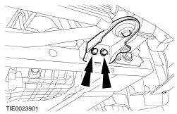
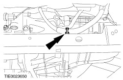
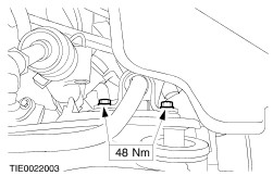
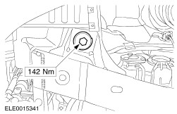
Remove the subframe rear retaining bolts and the subframe rear bracket retaining bolts (right-hand side shown). | | | -
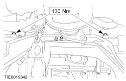
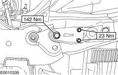
Remove the subframe front retaining bolts (right-hand side shown). | | | -
CAUTION:Lower the subframe uniformly, to prevent the lower arm hydro-bushings from damage. Using the transmission jack, lower the subframe approximately 150 mm. | | | -
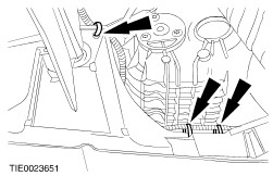
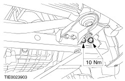
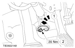
NOTE:Use a 5 mm Allen key to prevent the ball joint from rotating. Remove the stabilizer bar connecting links (left-hand side shown). | | | -
Detach the steering gear from the subframe. - Using cable ties, support the steering gear.
| | | -
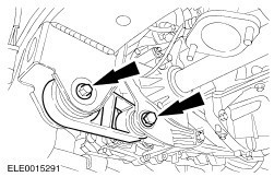
Remove the stabilizer bar (two bolts each side). | Installation All vehicles | | -
Install the stabilizer bar (two bolts each side). | | | -
Attach the steering gear to the subframe. | | | -
NOTE:Use a 5 mm Allen key to prevent the ball joint from rotating. Install the stabilizer bar connecting links (left-hand side shown). | | | -
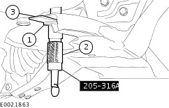
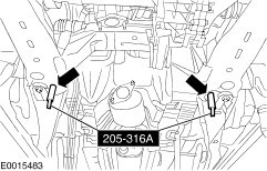
Using the special tool and a suitable washer, align the subframe. - Insert the washer, with inside diameter 22 mm, outside diameter 44 mm and height 5 mm, into the subframe above the lower alignment hole.
- Insert the alignment pins through the subframe alignment holes and the washer.
- Slide the locking plates on top of the washer and into the groove of the tool and tighten the alignment pin sleeve.
| | | -
CAUTION:While tightening the subframe retaining bolts, make sure the subframe does not move. Install the subframe front retaining bolts (right-hand side shown). | | | -
CAUTION:While tightening the subframe retaining bolts, make sure the subframe does not move. Install the subframe rear retaining bolts and the subframe bracket retaining bolts (right-hand side shown). - Lower and remove the transmission jack.
| | | -
Remove the special tools. | Vehicles with xenon headlamps | | -
Attach the headlamp leveling sensor wiring harness to the subframe. | All vehicles | | -
Attach the radiator cooling fan wiring harness to the subframe. | | | -
Attach the catalyst monitor sensor wiring harness to the subframe. | | | -
Connect the catalyst monitor sensor electrical connector. | | | -
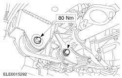
Install the engine rear support insulator. | Vehicles with 2.5L engine Vehicles with 1.8L, 2.0L or diesel engine All vehicles | | -
NOTE:Use a 5 mm Allen key to prevent the ball joint from rotating. Attach the stabilizer bar connecting links to the suspension struts (right-hand side shown). | | | -
Install the coolant hose support bracket. | | | -
Install the radiator support brackets (left-hand side shown). | | | -
Install the splash shield. | Vehicles with diesel engine | | -
Install the engine undershield. | All vehicles | | -
Remove the radiator support pins (left-hand side shown). | | | -
WARNING:Install a new steering column to steering column flexible coupling retaining bolt. Failure to follow this instruction may result in personal injury. Connect the steering column shaft to the steering column flexible coupling. - Rotate the clamp plate.
- Install the retaining bolt.
| |