| Removal and Installation Special Tool(s) | | Lever, Wheel Knuckle 204-159 (14-039) | | | Installer, Halfshaft 204-161 (14-041) | | | Alignment Pins, Subframe 205-316 (15-097A) | | | Separator, Ball Joint 211-020 (13-006) | General Equipment Transmission jack Three leg puller Removal All vehicles | | -
CAUTION:Use a socket to loosen the wheel hub retaining nut to prevent damage. Loosen the wheel hub retaining nut. | | | -
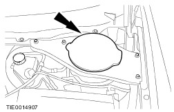
Remove the strut and spring assembly top mount brace cover. | | | -
CAUTION:Use an Allen key to prevent the piston rod from rotating. Loosen the strut and spring assembly top mount nut by five turns. | | | -
Disconnect the front wheel speed sensor electrical connector from the front wheel speed sensor. | | | -
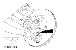
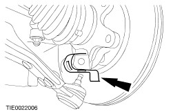
CAUTION:Leave the tie-rod end retaining nut in place to protect the ball joint stud. NOTE:Use a 5 mm Allen key to prevent the ball joint stud from rotating. Loosen the tie-rod end retaining nut. | | | -
CAUTION:Protect the ball joint seal using a soft cloth to prevent damage. Using the special tool, detach the tie-rod end from the wheel knuckle. - Release the tie-rod end.
- Remove the tie-rod end retaining nut.
| | | -
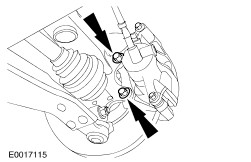
CAUTION:Suspend the brake caliper and anchor plate to prevent load being placed on the brake hose. Detach the brake caliper and anchor plate from the wheel knuckle. | Vehicles with diesel engine | | -
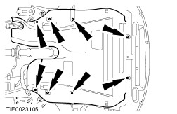
Remove the engine undershield. | All vehicles | | -
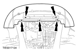
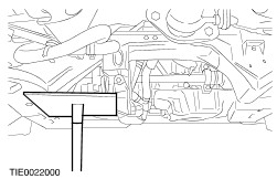
Detach the splash shield from the subframe. | | | -
NOTE:Only one side of the subframe needs to be lowered to detach the lower arm ball joint from the wheel knuckle. | | | -
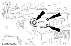
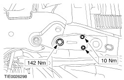
Remove the subframe rear retaining bolt and the subframe rear bracket retaining bolts, on the side the wheel knuckle is being removed (right-hand side shown). | | | -
Loosen the subframe rear retaining bolt and the subframe rear bracket retaining bolts, on the opposite side, by five turns. | | | -
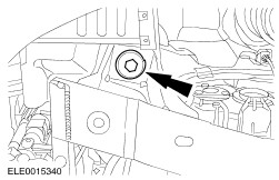
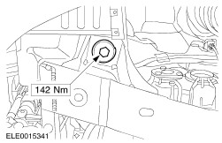
Remove the subframe front retaining bolt, on the side the wheel knuckle is being removed (right-hand side shown). | | | -
Loosen the subframe front retaining bolt, on the opposite side, by five turns. | | | -
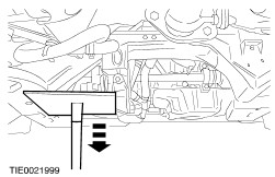
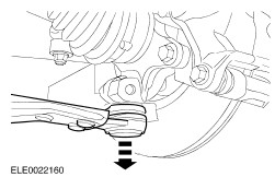
Lower the subframe to gain access to the lower arm rear retaining bolt. | | | -
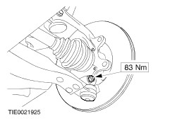
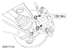
CAUTION:To prevent damage to the lower arm hydro-bushing, make sure the subframe is lowered before detaching the lower arm ball joint from the wheel knuckle. Remove the lower arm ball joint to wheel knuckle pinch bolt and nut. | | | -
CAUTION:Protect the ball joint seal using a soft cloth to prevent damage. Detach the lower arm ball joint from the wheel knuckle. | | | -
CAUTION:The wheel hub retaining nut can be re-used four times, mark the retaining nut. Remove the wheel hub retaining nut. | | | -
Remove the wheel knuckle to suspension strut pinch bolt. | | | -
CAUTION:Support the halfshaft. The inner joint must not be bent more than 18 degrees. The outer joint must not be bent more than 45 degrees. Using a suitable three leg puller, detach the wheel hub from the halfshaft. | | | -
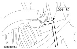
Using the special tool, remove the wheel knuckle. | Installation All vehicles | | -
Install the wheel knuckle. | | | -
CAUTION:Make sure the halfshaft is completely installed into the wheel hub. Using the special tool, attach the wheel hub to the halfshaft. | | | -
CAUTION:Make sure the heat shield is installed to prevent damage to the ball joint. Install the heat shield. | | | -
CAUTION:The lower arm pinch bolt must be installed from the rear of the wheel knuckle. Attach the lower arm ball joint to the wheel knuckle. | | | -
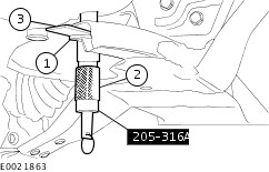
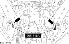
Using the special tool and a suitable washer, align the subframe. - Insert the washer, with inside diameter 22 mm, outside diameter 44 mm and height 5 mm, into the subframe above the lower alignment hole.
- Insert the alignment pin through the subframe alignment holes and the washer.
- Slide the locking plates on top of the washer and into the groove of the tool and tighten the alignment pin sleeve.
| | | -
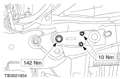
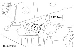
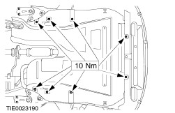
CAUTION:While tightening the subframe retaining bolts, make sure the subframe does not move. Install the subframe rear retaining bolt and the subframe bracket retaining bolts, on the side the wheel knuckle was installed (right-hand side shown). | | | -
Tighten the subframe rear retaining bolt and the subframe bracket retaining bolts, on the opposite side (left-hand side shown). | | | -
CAUTION:While tightening the subframe retaining bolts, make sure the subframe does not move. Install the subframe front retaining bolt, on the side the wheel knucle was installed (right-hand side shown). | | | -
Tighten the subframe front retaining bolt, on opposite side (left-hand side shown). - Lower and remove the transmission jack.
| | | -
Remove the special tools. | | | -
Attach the splash shield to the subframe. | Vehicle with diesel engine | | -
Install the engine undershield. | All vehicles | | -
Attach the brake caliper and anchor plate to the wheel knuckle. | | | -
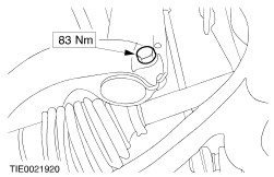
WARNING:Install a new tie-rod end retaining nut. Failure to follow this instruction may result in personal injury. NOTE:Use a 5 mm Allen key to prevent the ball joint stud from rotating. Attach the tie-rod end to the wheel knuckle. | | | -
CAUTION:The wheel hub retaining nut can be re-used four times, inspect the markings on the retaining nut and install a new retaining nut if necessary. With the aid of another technician, apply the brakes and pre load the wheel bearing by installing the wheel hub retaining nut. | | | -
Connect the front wheel speed sensor electrical connector to the front wheel speed sensor. | | | -
Tighten the wheel hub retaining nut. | | | -
CAUTION:Use an Allen key to prevent the piston rod from turning. Tighten the strut and spring assembly top mount nut. | | | -
Install the strut and spring assembly top mount brace cover. | |